Week 10- Assembly Workbench
Model Drawing 1
Part models
procedure
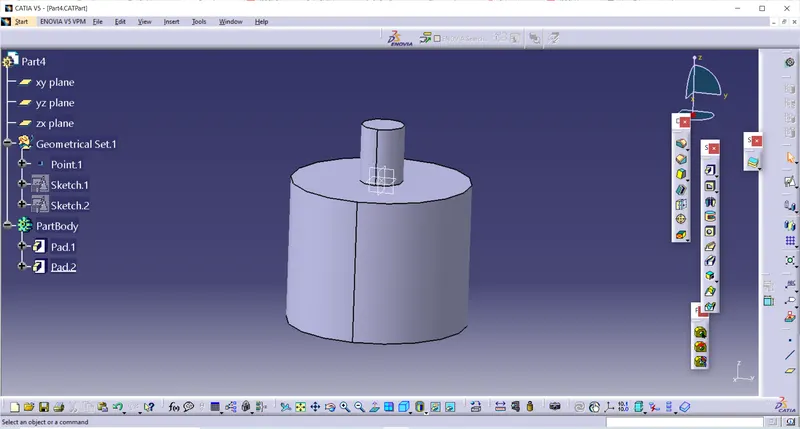
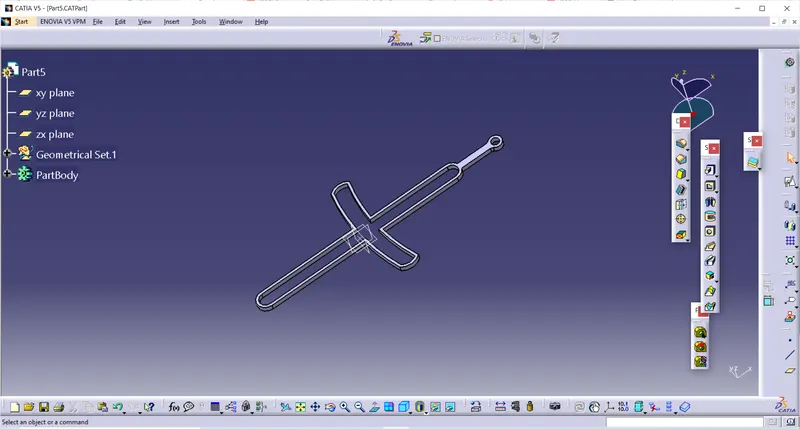
- Given part is created with the given dimension in mechanical part design workbench.
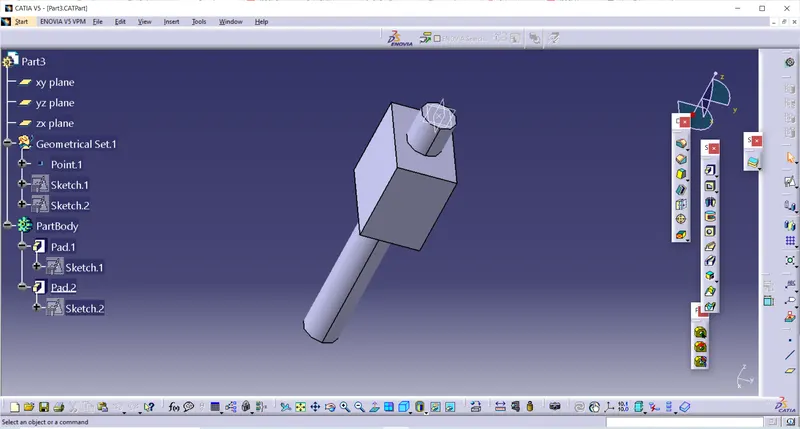
- The images are follow.
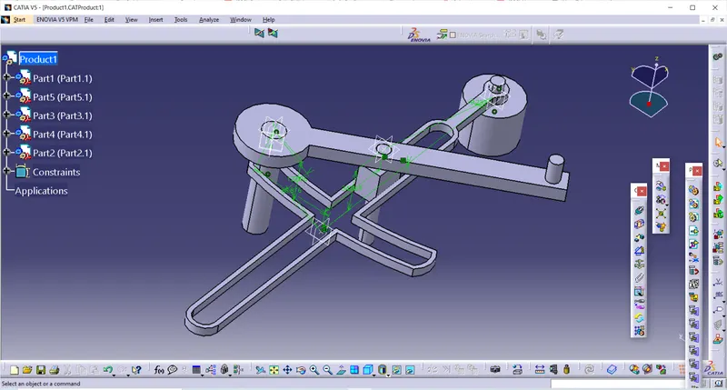
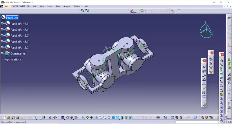
- After creating all the part by given dimension it all loads in mechanical assembly workbench .
- Then by using constraints it is align properly.
- Coincidence constaint, contact constrain and offset contrain are use.
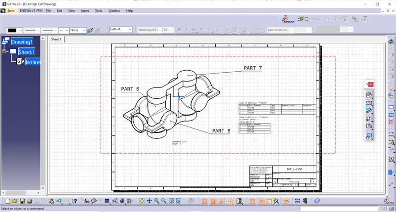
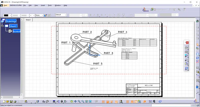
- After completing assembly the isometric vieew of assembly load in 2D drawing.
- As shown in below image.
1.
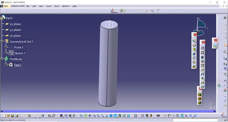
Diameter with 10 rod is created and pad for 50mm.
2.
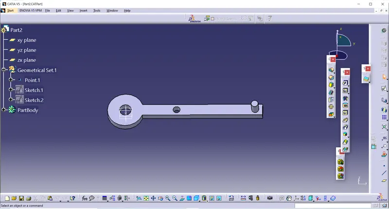
Given part is created with the given dimension in mechanical part design workbench.
3.
4.
5.
Assembly Model 1.
2D Drawing
Model 2 .
part 1
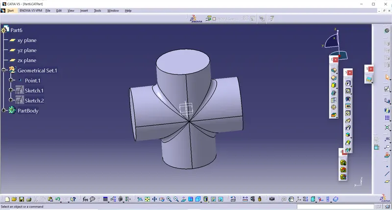
Part 2
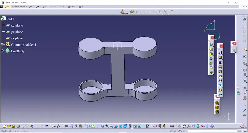
Part 3.
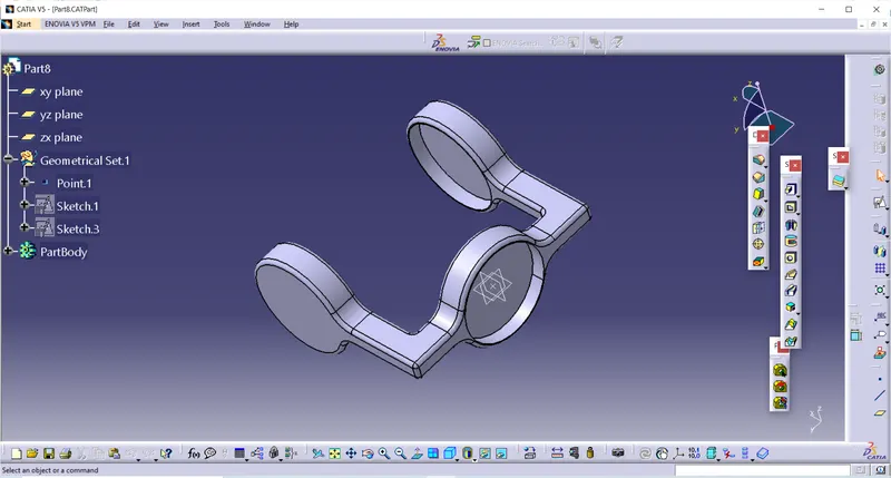
Assembly model 2
2D Drawing