Project 1
Define the connector
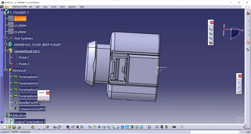
- Load the connector in mechanical part design give points and plane.
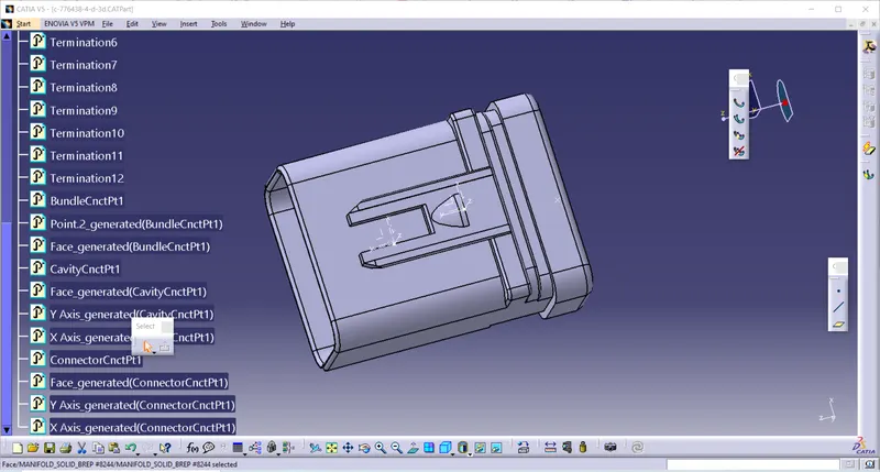
- Then go to the electrical part design and define it as a connector and give bundle connection point and connector conection point and also cavity connection for the connector.
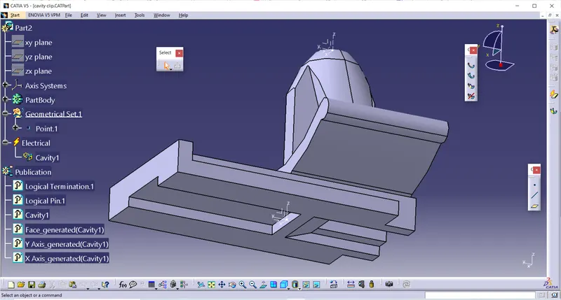
- Define cavity as an support then as cavity.
- Likewise all the connector should be define.
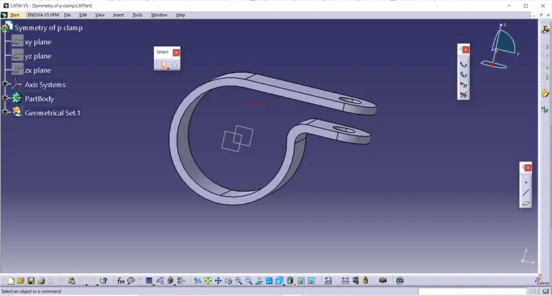
Define p clamp
- for p clamp it has one entry and one exit .
- so define point on both entry and exit by using point defination
- Do this on both side .
- next define the plane on both side.
- now define plane on bottom side.
- for that go to the plane definition and select offset from plane.
- select reference as bottom surface and take offset of 2mm
- after doing this select ok the plane will be created.
- after this go to the electrical part design to defined as support.
- in that for entry side select point and plane from entry side .
- for second plane definition select opposite plane and for base plane definition select base plane.
- select ok .
- same procedure for the exit side also.
- this is how p clamp is defined as a support.
Define channel bottom
- We use channel because it is suitable for compact area.
- Load the channel bottom in part design give two points on the surface to create line.
- Shown below
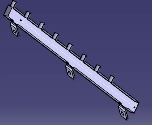
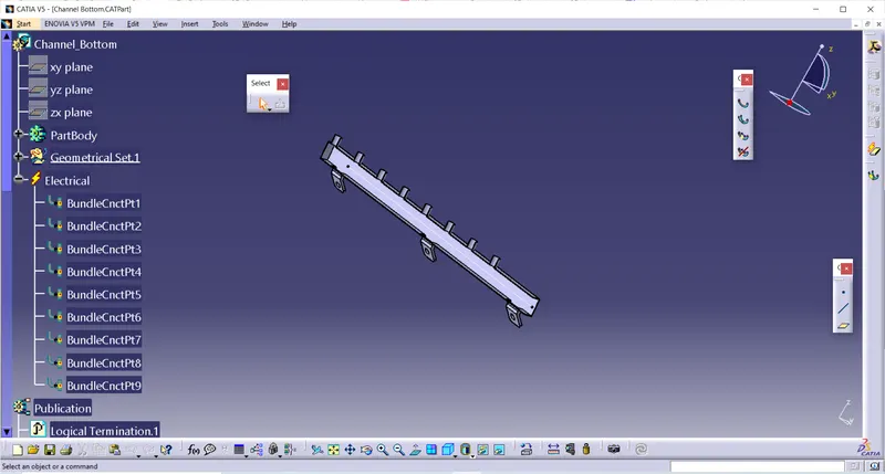
- Define bundle connection point on entry of channel bottom.
- And also on the branch of channel bottom
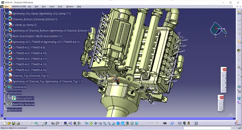
Now placed the connector on engine.
- place the connector on the respective side of the engine.
- By using manipulation command, snap command and others.
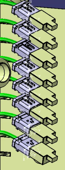
- on opposite sid3e also.
- also placed the remaining connector also
- as shown in fig.
Bundle routing
- Go to the electrical harness assembly.
- start the routing with the interconnector .
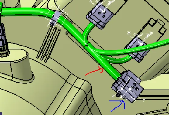
- The connector indicate by blue arrow from that starts branch routing.
- The branch indicate in red red arrow is main branch.
- The diameter of branch is 15mm and other branches has 10mm and 8mm.
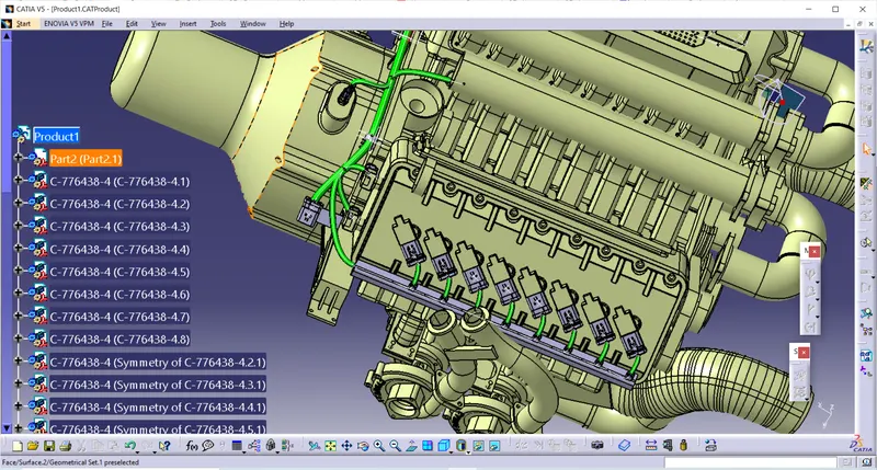
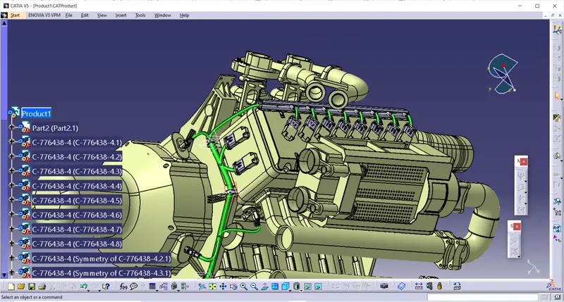
- Same way all the branching is done.
right side
left side
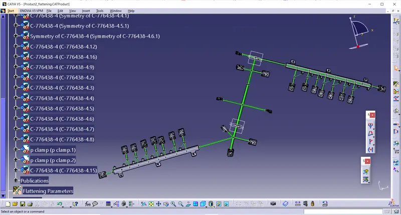
flattening
- Go to the new create a product and then go to harness flatening assembly.
- Set the configuration and extract multibranch.
Drawing
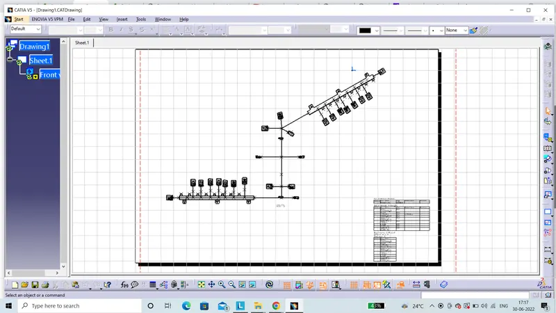
- Again go to the new file as a drawing.
- select the front view and click on the flatening.
- it will appear in drawing.
- as follow.