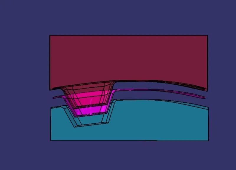
Core & Cavity Design
OBJECTIVE:
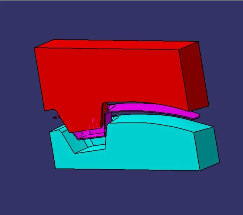
To design a Mold cavity for switch Bezel and conduct the Analysis in CATIA V5
INTRODUCTION:
Plastic molding is the process of shaping plastic using a rigid frame or mold. The technique allows for the creation of objects of all shapes and sizes with huge design flexibility for both simple and highly complex designs. A popular manufacturing option, plastic molding techniques are responsible for many car parts, containers, signs, and other high-volume items.
- Core & Cavity:
These are the shaped sections that help in creating the part. They provide a gap between them according to the thickness of the part and also majorly the part surface finish will be depended on the Mold.
so, For this case, the designer should concentrate more on the finishing of the core and cavity.
- PARTING LINE:
The parting line is the borderline of the body, which actually splits the core and cavity. It is sometimes a starting point for the mold parting surface. It majorly helps in reducing the flash.
- PARTING SURFACE:
The parting surface is the face of both the core and cavity which actually helps in a tight seal to avoid the material escaping from the mold.
PROCEDURE:
- CREATING PARTING SURFACE:
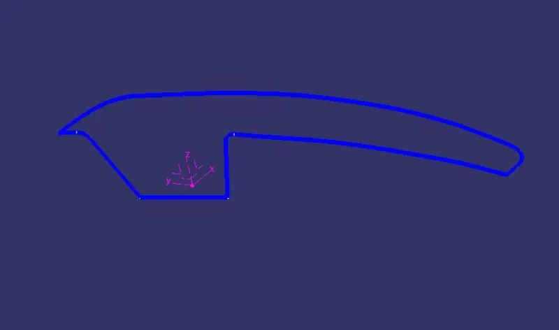
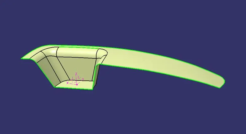
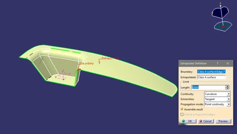
- Extract the face of the part And extrapolate it with 15mm
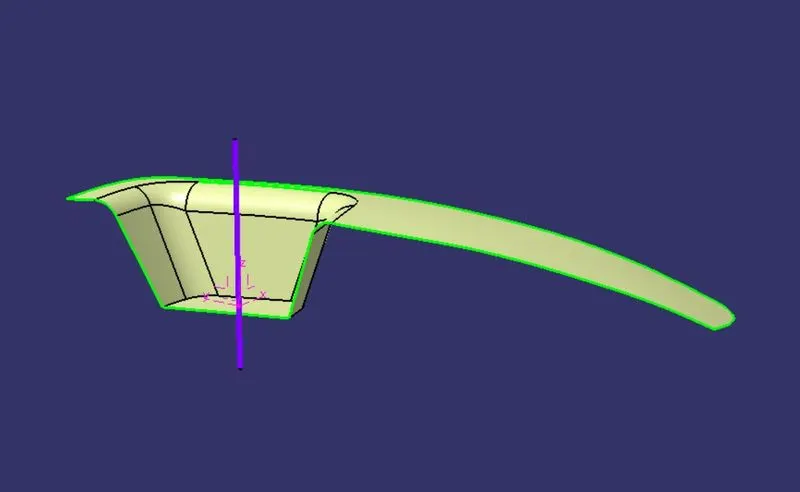
- Extract the B surface,
- Now trim the extracted face with B-surface.
- PREPARATION OF CORE DESIGN:
- Select the top view and create a sketch as a rectangular profile.
- Then extrude the rectangular profile.
- Extract the parting surface and trim it with the extruded surface.
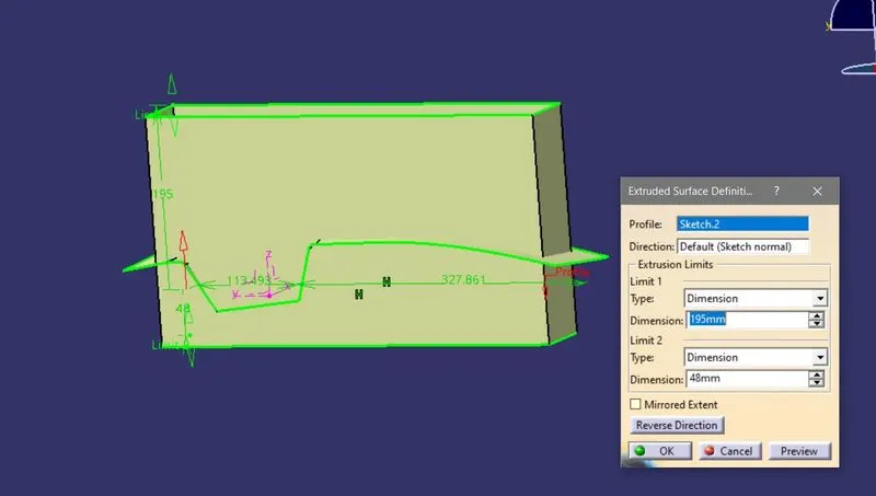
- Now fill the open surface by selecting the edges of the extruded part.
- Join both fill surfaces with the trimmed part.
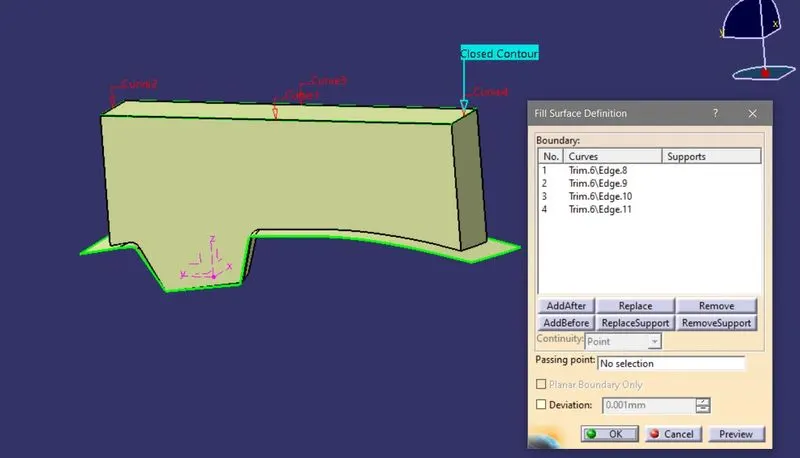
- Add the material by converting the surfaces into a solid part.
- PREPARATION OF CAVITY DESIGN:
- Extract the B surface from the part.
- By using the extruded part trim them with B-surface.
- Repeat the same procedure by using the edges to fill the surface.
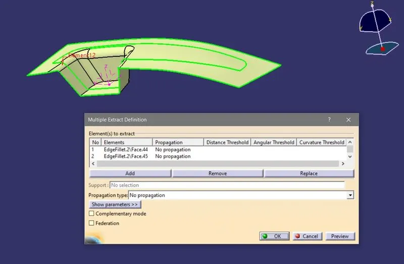
- Now Join the surfaces both fill surface and trimmed part to make a cavity.
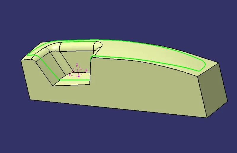
- Add the material by converting the surfaces into a solid part.
- PROCEDURE FOR DRAFT ANALYSIS:
- Go to the Insert menu and select the analysis option.
- select the feature draft analysis
- Drag the compass along the tooling axis direction
- Lock the compass and click on the object to check for the draft
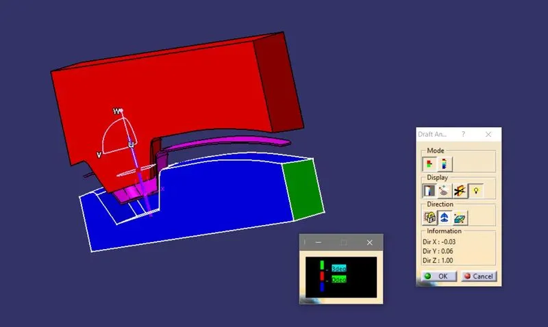
- Now if the results are according to our requirements then click on Ok.
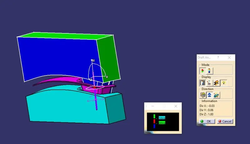
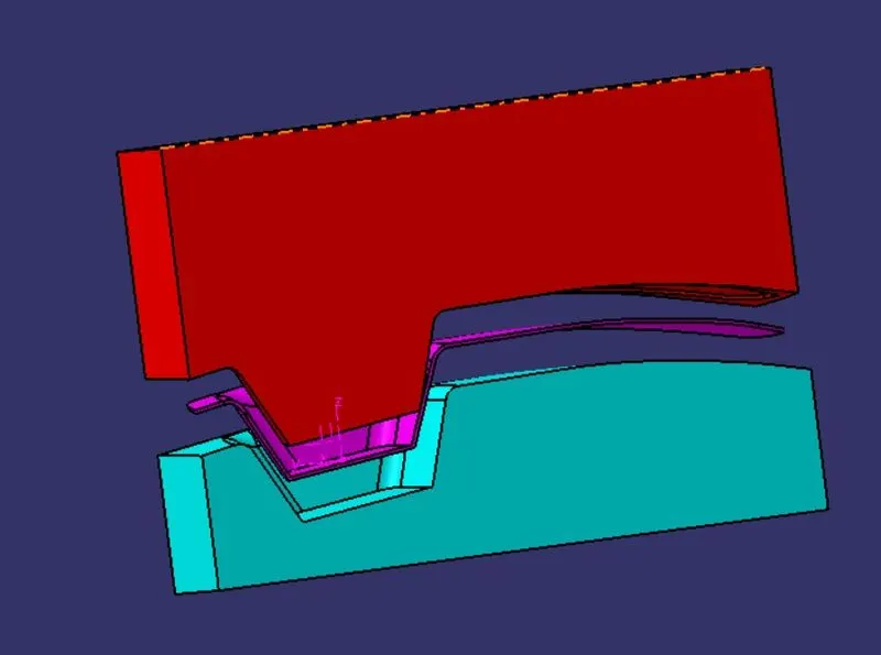
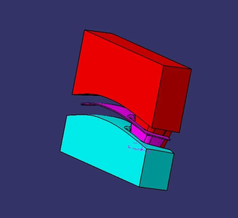
VIEWS OF CORE AND CAVITY: