Base Bracket Design in Catia V5
OBJECTIVE:
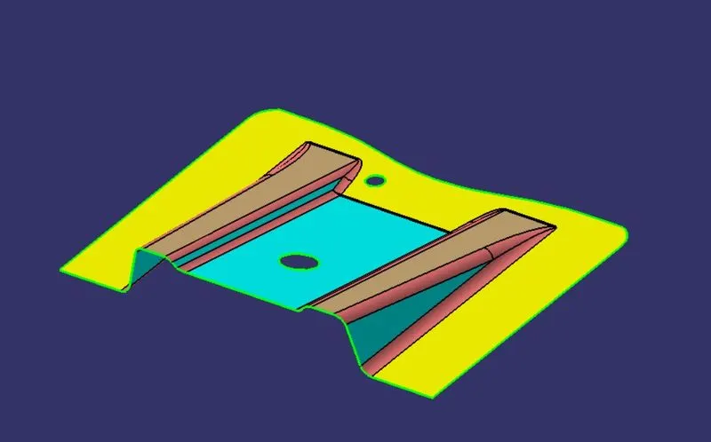
To design the Base Bracket by using the Class A surface in CATIA V5
Introduction:
By using the Class A surface we are going to create a solid part by following OEM regulations. The designed part should be ready for molding so, the part is designed by assigning the proper draft.
PROCEDURE:
- Import the class A surface and check for the patches on the surface.
- Add the point at an appropriate location and create a new axis system at the point location.
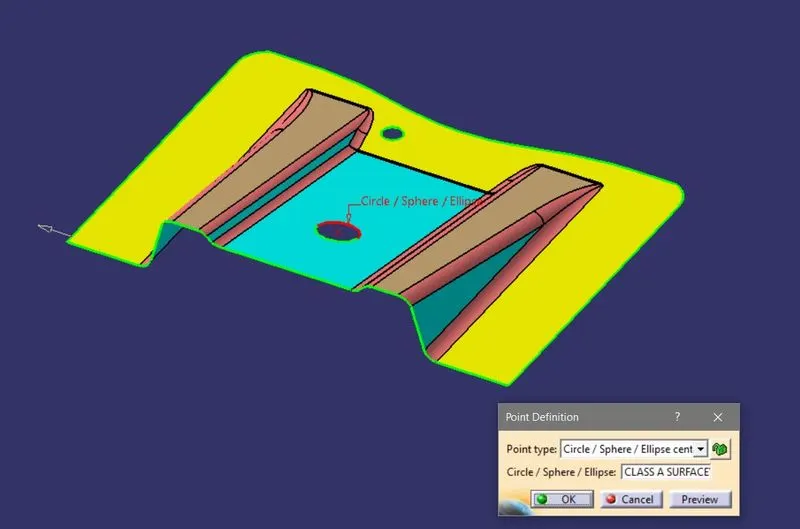
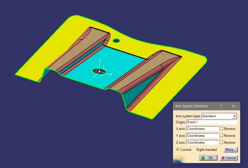
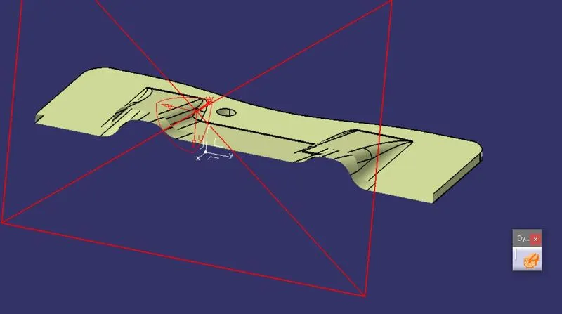
- Create an intersection geometry between the surface and xz plane,
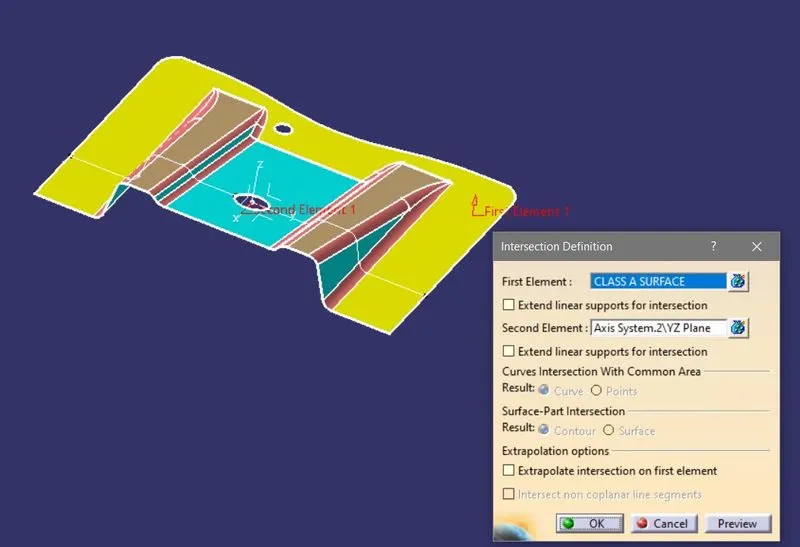
- Then create the two lines along the intersection by taking the reference angle of the surface body, and create a new line by using the Bisecting command for creating the original tooling axis.
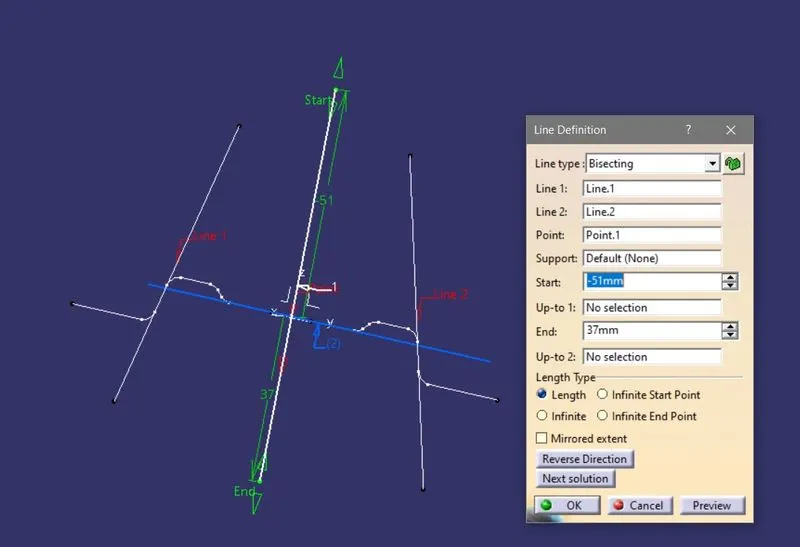
- After that extract the faces and trim them according to the requirement which creates rib sections,
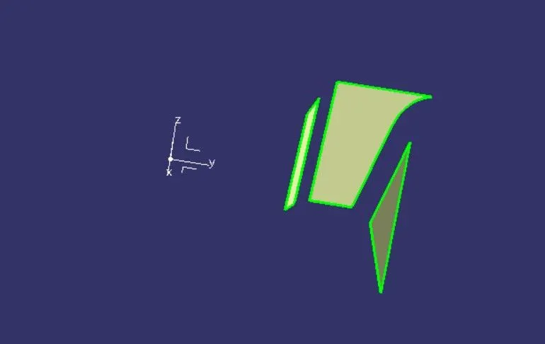
- By using the extrapolate increase the length of the surface and join them accordingly.
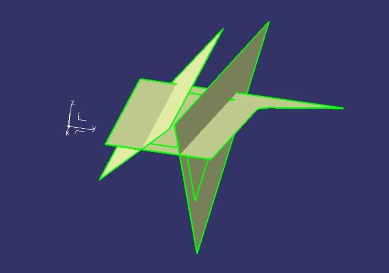
- Now offset the trimmed sections with considering the thickness of the part as 2.5mm
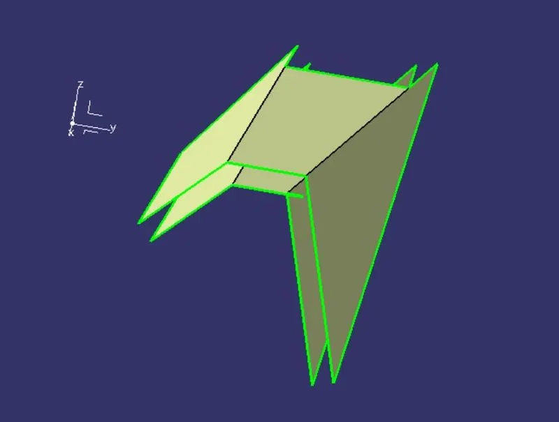
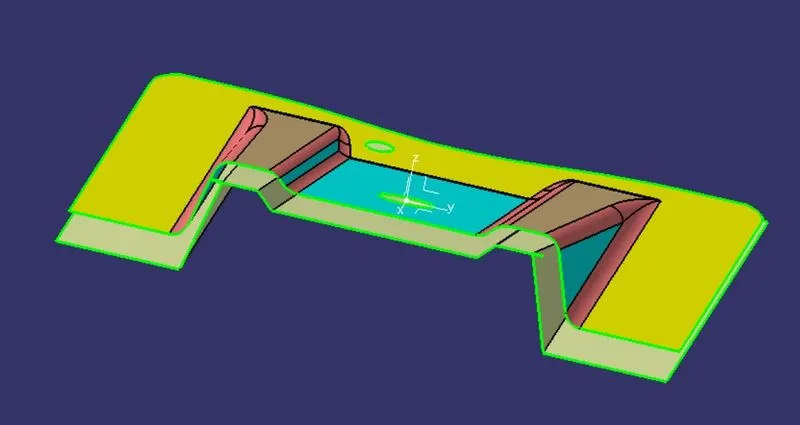
- create an individual boundary for adding the surface material with the proper draft angle in the Sweep command.
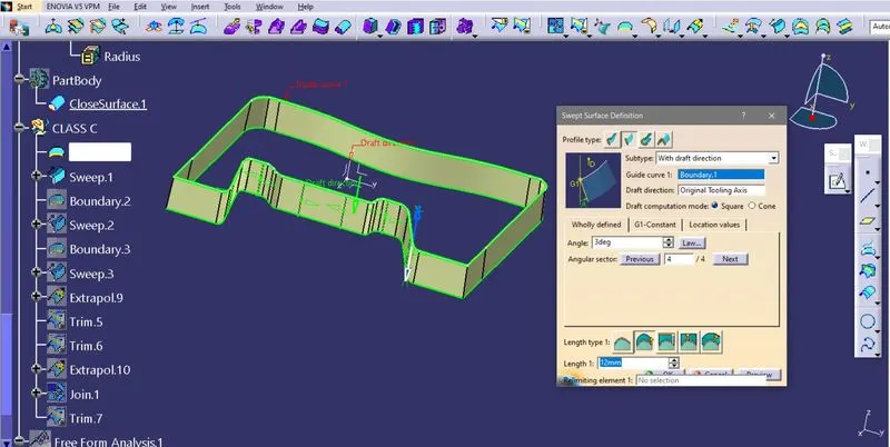
- then add the fillets to the Class B surface,
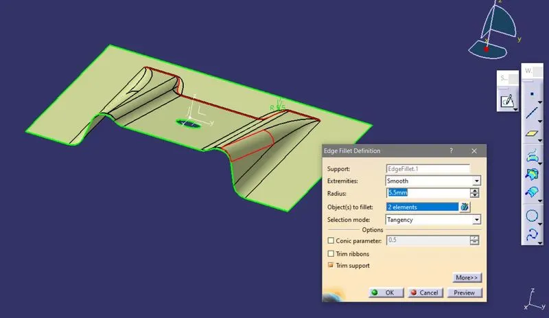
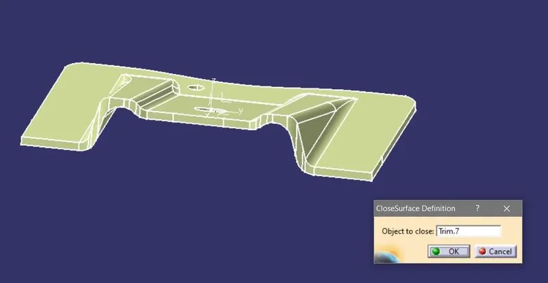
- Now By using the Trim and Join Commands accordingly create a closed Surface body.
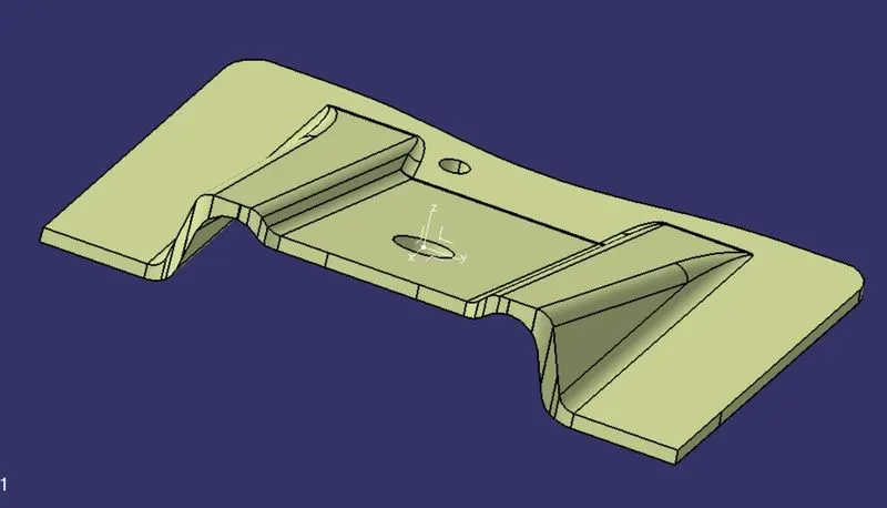
- By using close body command create a thickened part.
- After creating the part check for the proper draft with the help of draft anal
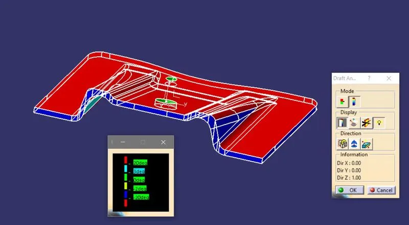
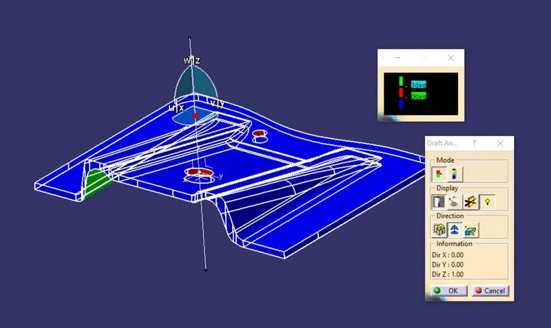
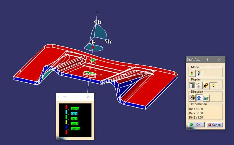
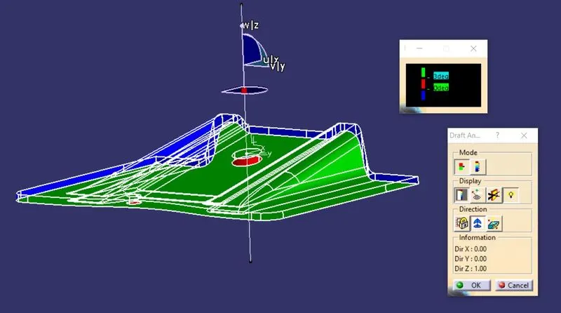
CONCLUSION:
In this project designed the base bracket and made ready for manufacturing by allowing a proper draft according to the requirement.