B-Side Feature Creation
OBJECTIVE:
To create B-side features on the Plastic part( coin Holder) in CATIA v5.
Boss Creation:
The boss is one of the basic design elements of plastics molding. Bosses are usually cylindrical because that is the easiest form of a machine in the mold and it is also the strongest shape to have in the molded part. The boss is used whenever we need a mounting point, a location point, a reinforcement around a hole, or a spacer. The boss may receive an insert, a screw, or a plain shaft either as a slide or a press fit. In other words, the boss is not as simple as it looks. Depending on its use, it may have to stand up to a whole combination of forces – tension, compression, torsion, flexing, shear, and bursting - so it must be designed accordingly.
SCREW BOSS NOMENCLATURE:
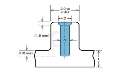
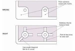
Rigidity is the simplest aspect of boss design. This can be achieved by supporting the boss with buttress ribs, and often by linking the boss to a sidewall. The support ribs can be designed to normal rib rules so that sink marks and stress points are avoided. When the boss is linked to a side wall, either at an edge or the corner of a component, there is a right and a wrong way to do it. The wrong way is simply to extend the boss outside diameter to meet the wall. This inevitably produces a thick section that will result in sink marks, voids, and long cooling cycles. The right way is to link or tie the boss to the sidewall with a flat rib, preferably recessed a little below the boss or edge height so that it cannot interfere with any assembly conditions.
We can start with some general design rules, using the principles we have already developed for ribs and walls. The boss can be thought of as a special case of a rib; one that is wrapped round in the form of a tube. An 'ideal' boss, designed according to rib rules, would not produce sink marks or stick in the mold.
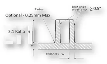
Guidelines for Design of Screw Boss:
- The thickness of the wall is 0.4times of a part thickness(0.4T).
- The draft should be ≤5degree on the walls of the boss.
- The height to the Diameter ratio is 3:1
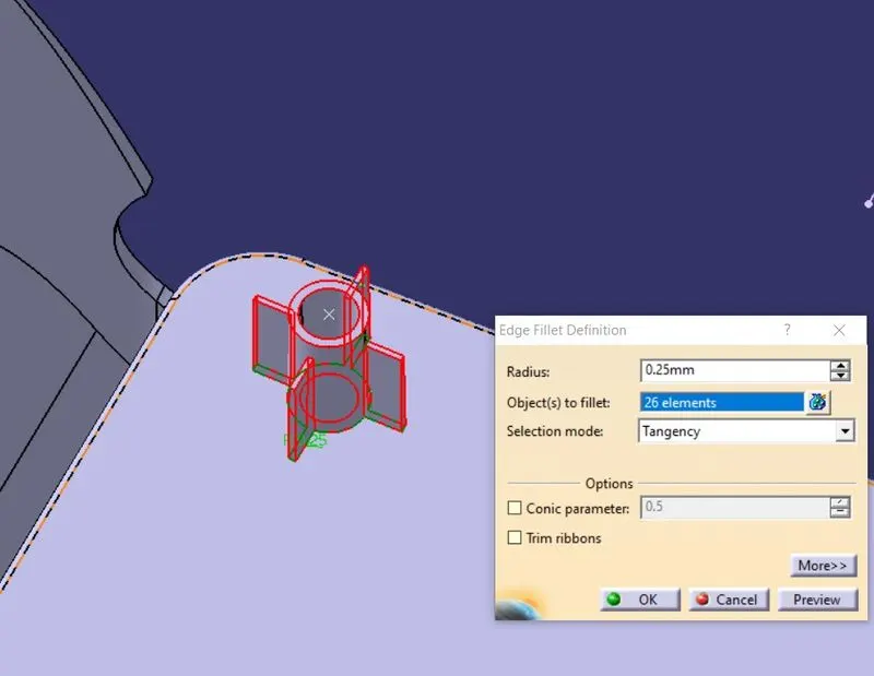
- Radii are 0.5mm.
Design Procedure:
- Import the coin holder into the workbench and extract the face for creating a center point.
- Create a point on the surface and with the help of that point create a line that is perpendicular to the surface for the main tooling axis.
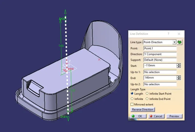
- Now select the B-side Face and create a sketch for screw-boss with the following guidelines and constraint the sketch.
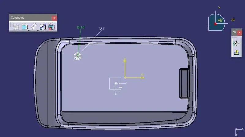
- Then with the help of the PAD feature add the material along the tooling axis direction, also add the thickness of 0.4T.
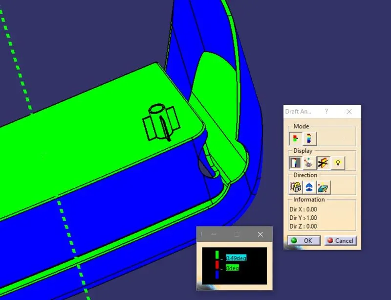
- Add the draft to the walls with a 0.5degrees angle.
- Create the sketch for the supports of Screw Boss and constraint them.
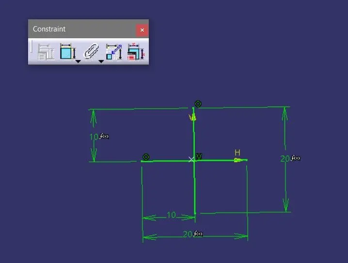
- Then by using the thickness feature add the material to the sketch along the tooling axis direction.
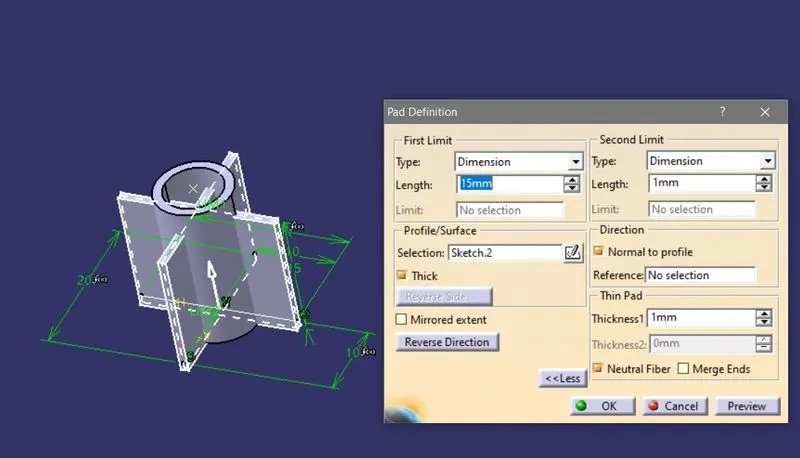
- Now add the draft to the walls with a 0.5degrees angle.
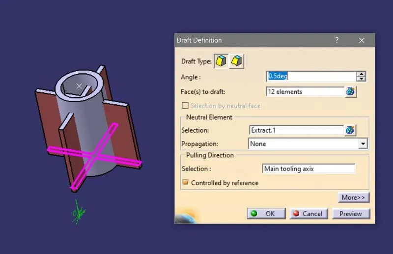
- With the help of the Union trim feature perform the Boolean operation.
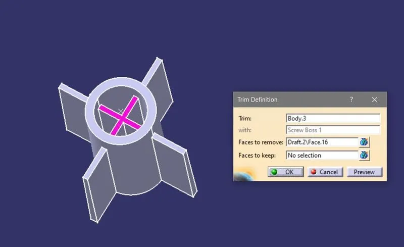
- Then Assemble this to the main body.
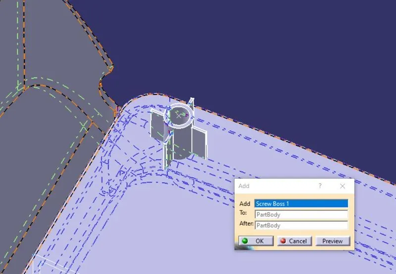
- Add the fillets to the edges of the screw boss to avoid the stresses with radii of 0.25mm.
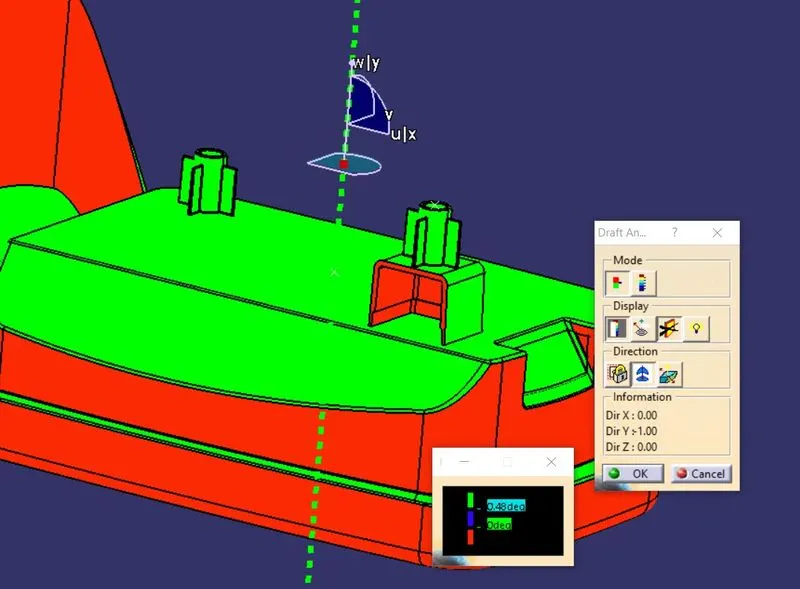
- Do the Draft analysis on the part to check whether the part is ready for manufacturing.
DOGHOUSE Creation:
The dog house is the B-side feature created on the plastic trims. This is mostly added to avoid the sink marks. Actually, these sink marks are produced by other features like ribs and screw bosses, due to their thickness the material flow will be affected while manufacturing and causes the sink marks. So, to avoid this the dog house is created, which is having legs with less thickness compared to the other features. And also it has other uses like with this dog house we can assemble the parts with larger distances and here we have a provision to add screw bosses in the other direction which are perpendicular to the side face of Dog house.
Guidelines for creation of Doghouse:
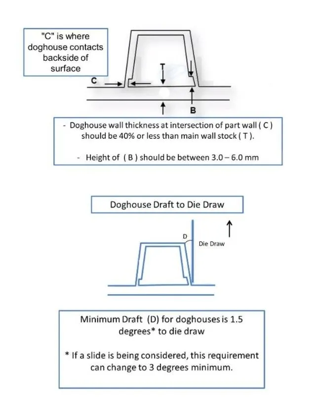
Design Procedure:
- Import the part into the workbench and create a tooling axis.
- Then select the B-side Face and add a sketch on it with the required profile.
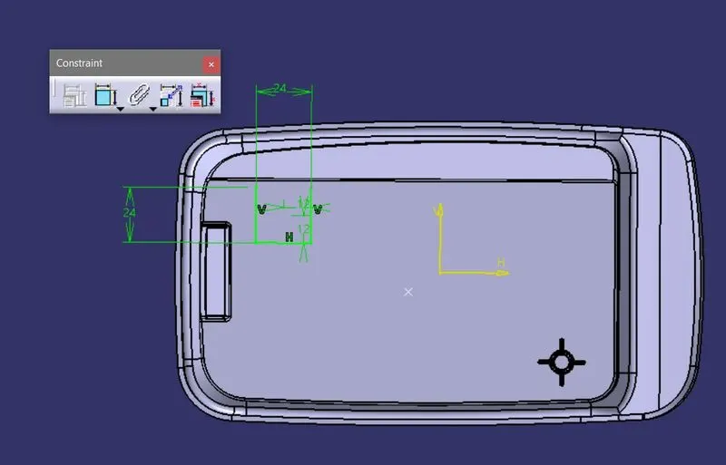
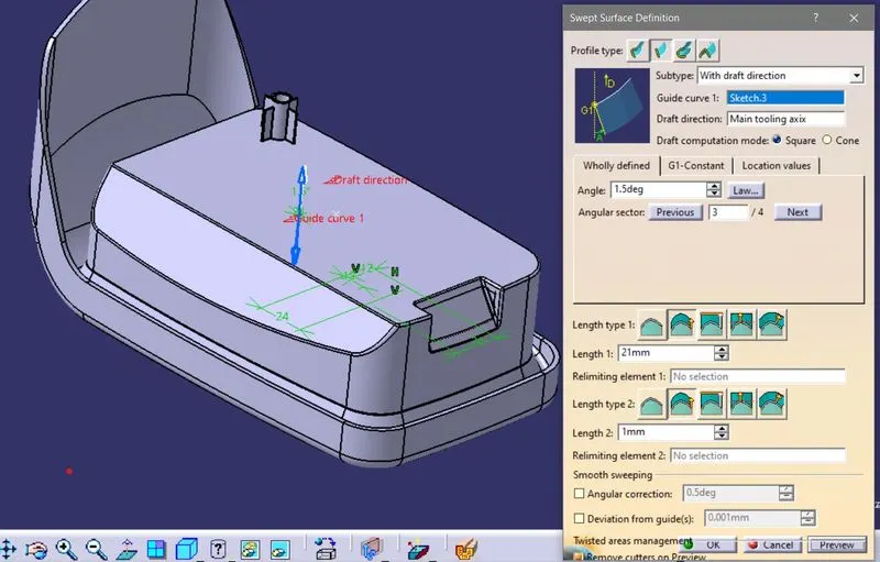
- Now by using the sketch add surface in that profile shape with a draft angle of about 1.5degrees.
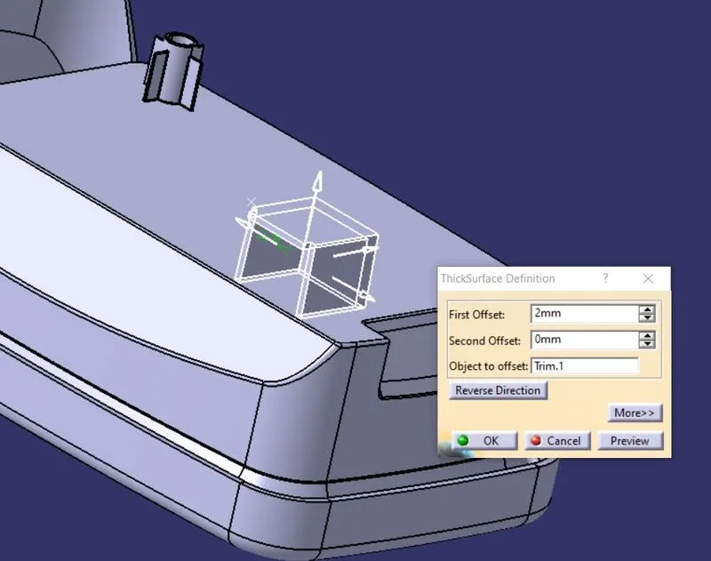
- Add material to the sweep surface with a 2mm thickness by using thicken feature.
- Extract the back face of the dog house to create a good surface finish.
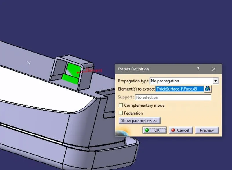
- And extrapolate the extracted surface and offset it to the required length.
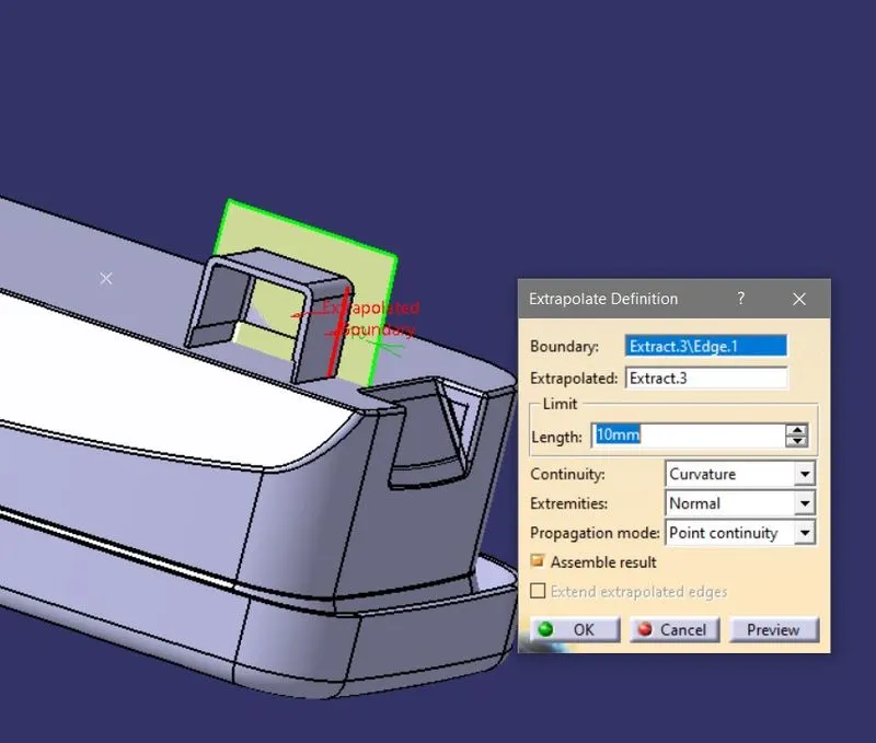
- Perform the split operation on the part by limiting the offset surface to chop the excess portion.
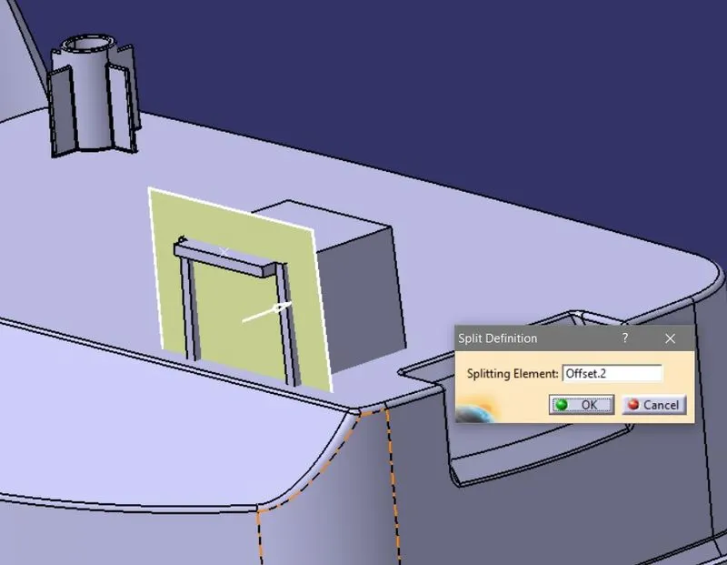
- Now offset the inside faces up to 1mm outwards as per the figure,
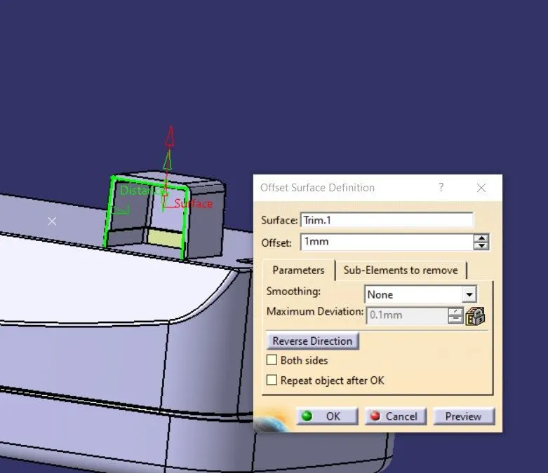
- Also, offset the extracted face in a perpendicular direction.
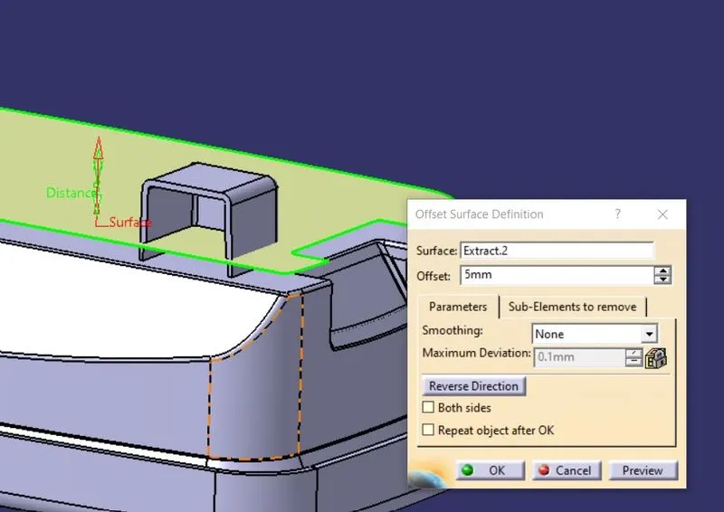
- Perform the Trim operation in order to get the shape of dog house legs.
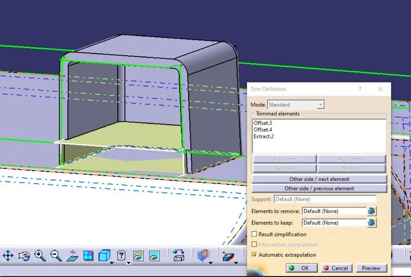
- Use the trimmed surface and do the split operation to extract the shape of legs for the dog house.
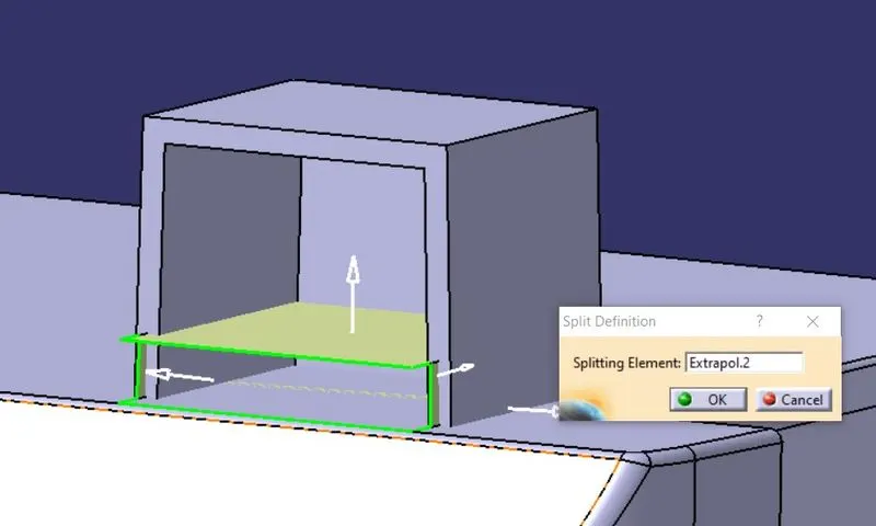
- Now Align the Screw boss according to the requirement and add it to the dog house.
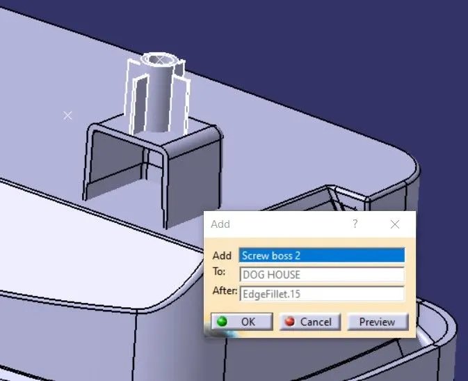
- Add the fillets to their edges with a radius of 0.5mm and 0.25mm respectively.
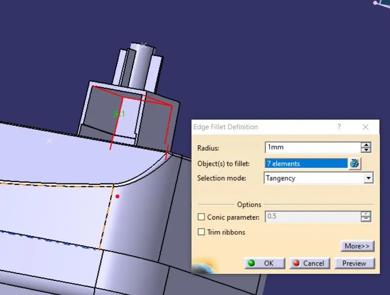
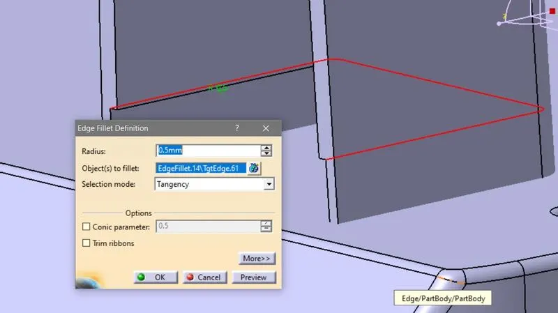
- Now Assemble these features to the main part.
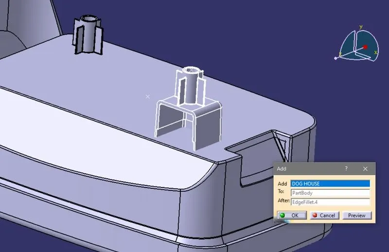
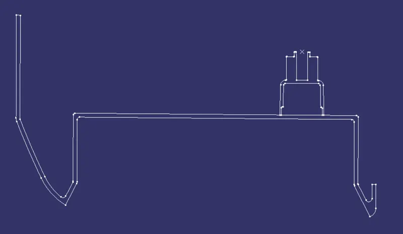
- Check for the design rules with the intersection profile of the whole part.
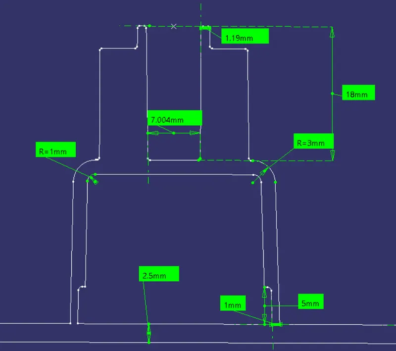
- Then do the draft analysis to check for the part which is under constraints angle and ready for manufacturing or not.
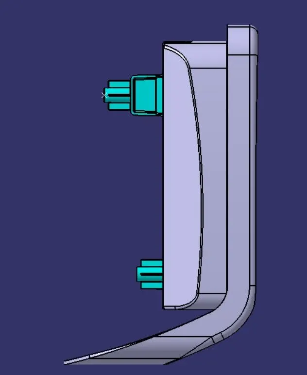
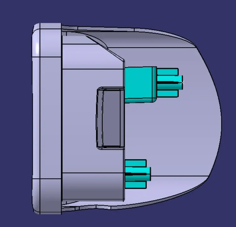
Views OF Coinholder Part:
CONCLUSION:
Created the B-side features Screwboss and Dog house, also conducted the analysis to Check whether the part satisfies the Design Guidelines.