Sheet Metal Design of Odd Shaped Enclosure
TITLE: Advance sheet metal design of Odd shaped enclosure.
OBJECTIVE: To design an Odd shaped enclosure by using the NX CAD tool.
INTRODUCTION:
Sheet metal is a comprehensive cold working process for metal sheets (usually below 6mm), including shearing, punching, folding, riveting, forming (such as car body structure).
SHEET-METAL NX: The NX sheet-metal interface has a set of tools that help in designing and modeling the sheet to our required form.
SOLID TO SHEET-METAL: This operational command helps in converting the solid body to the sheet with the access to use the same sheet metal features in the converted part down line.
EXTRUDE: A solid body will be created by selecting the sketch and sweeping along the desirable vector.
FLANGE: A bend is created by adding the material to an edge by using the flange command feature in bend (family).
JOG: This can be activated by selecting it from Bend (more gallery). It actually creates a bend portion upon our requirement by assigning the required height.
BEAD: This feature is activated by selecting the sketch and assigning the required radius of it from the punching group (BEAD COMMAND).
HOLES: This creates a-holes by selecting the command from the design feature group and it can be activated by assigning types of holes on our requirement.
UNBEND: It actually activates by selecting it from the FORM group and flattens the sheet.
REBEND: This feature is activated by selecting the command from the FORM group and makes the part into it original shape by applying a single stationary face.
DESCRIPTION:
DESIGN METHODOLOGY:
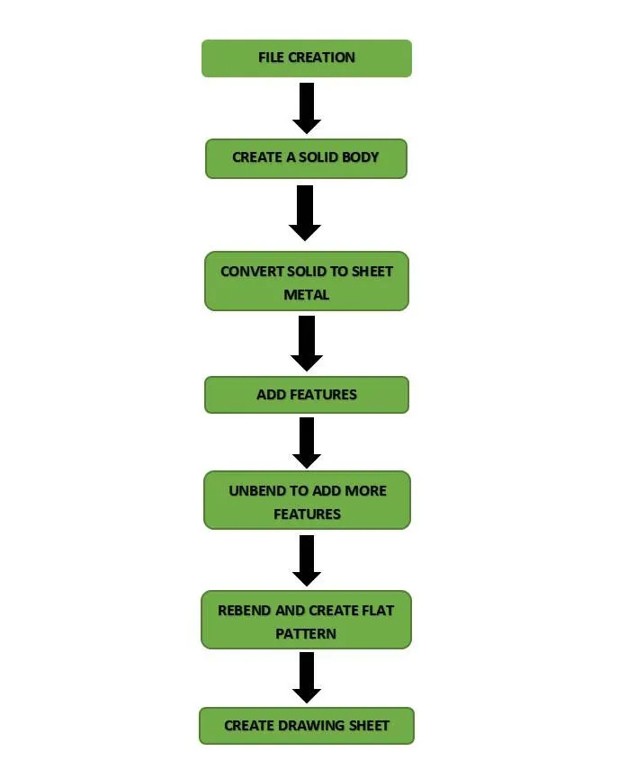
PROCEDURE:
- Open the NX cad software and create a new file by choosing a sheet-metal module by giving Odd shape enclosure as Filename.
- By selecting the XZ plane draw a sketch and add extrude to the sketch of 200mm distance.
- Then convert this solid body to sheet-metal by selecting the feature called Sheet-metal from solid and select the appropriate edges to get the required model.
- Add the flange material to an edge of a sheet metal body with a length of 20mm at 90deg.
- Select the JOG command a dialogue box appears, draw the required profile, and by giving the height of 20mm create a bend portion in the desired form.
- Unbend the sheet body by selecting the stationary face to add the modeling features to it.
- Create bead profiles as per the requirements from the rule book.
- Make the holes on selecting the points with a 10mm of diameter as mentioned in the rule book
- REBEND the unbended portions.
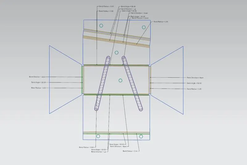
- Then create a flat pattern on selecting the top face of the sheet body.
- Go to model views to view the flat pattern mode.
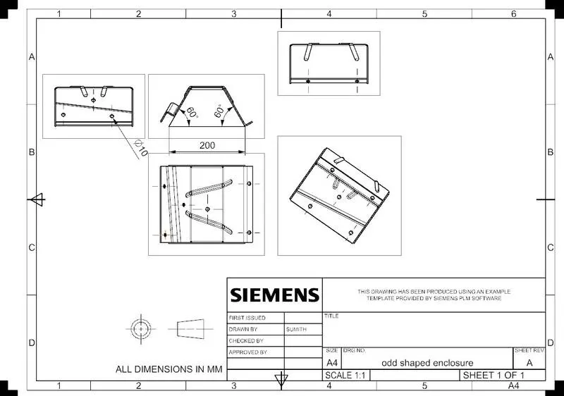
- And create a drawing sheet by selecting the drafting mode from the application.
Odd shaped enclosure views:
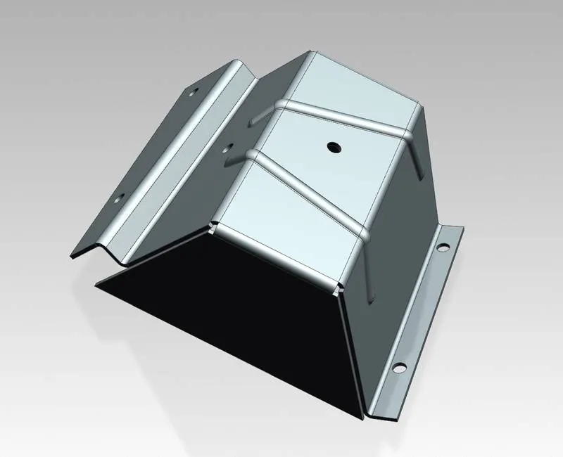
ISOMETRIC VIEW
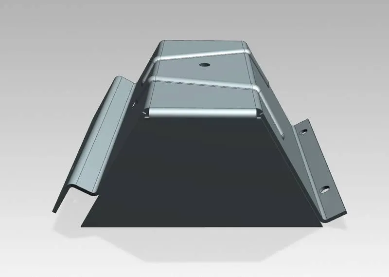
FRONT VIEW
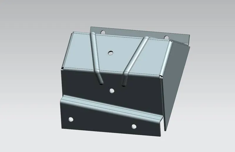
SIDE VIEW
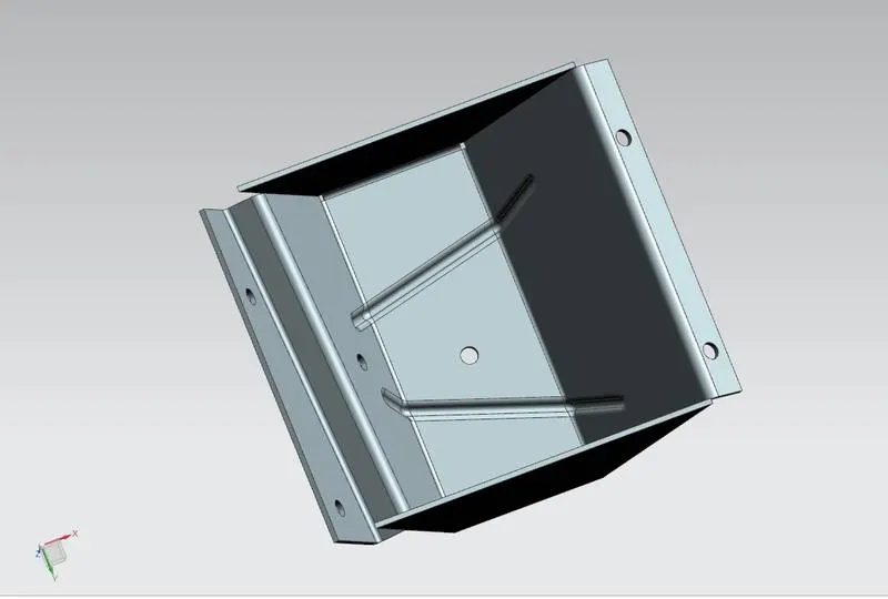
BACK SIDE VIEW
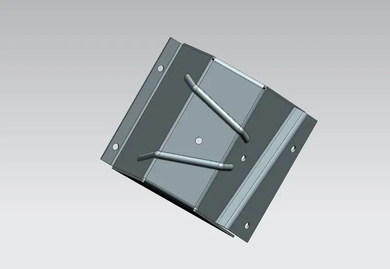
TOP VIEW
FLAT PATTERN VIEW:
DRAWING SHEET:
CONCLUSION:
By this challenge learned more modeling features and also gained knowledge on the importance of converting solid body to sheet metal.