Week 8 - Challenge 3 - Switch Bezel Design
AIM: Create the Switch Bezel Plastic component through the given Class-A surface. The tooling axis for the given Class-A Surface should be created to meet the draft angle requirements and, in the end, perform the Draft analysis on the model.
SOFTWARE: CATIA v5
PROCEDURE:
- The Tooling Direction is the direction that the mould pulls apart—the mould is built in two separate pieces.
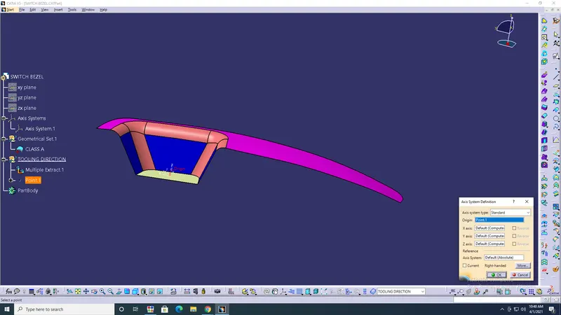
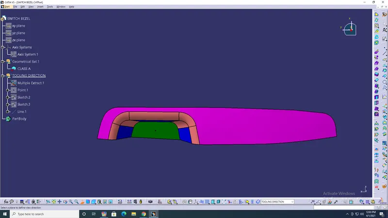
- Create point> on base surface> create axis system> on point> ok.
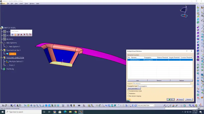
- Multiple extract> select base from class A surface> hide class A surface> ok.
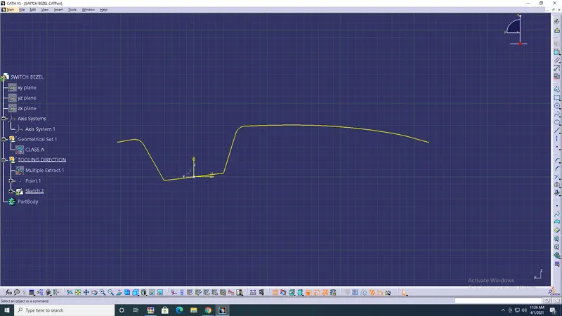
- Draw a line with sketch> both sides> create bisecting lines> change lines into construction elements> ok.
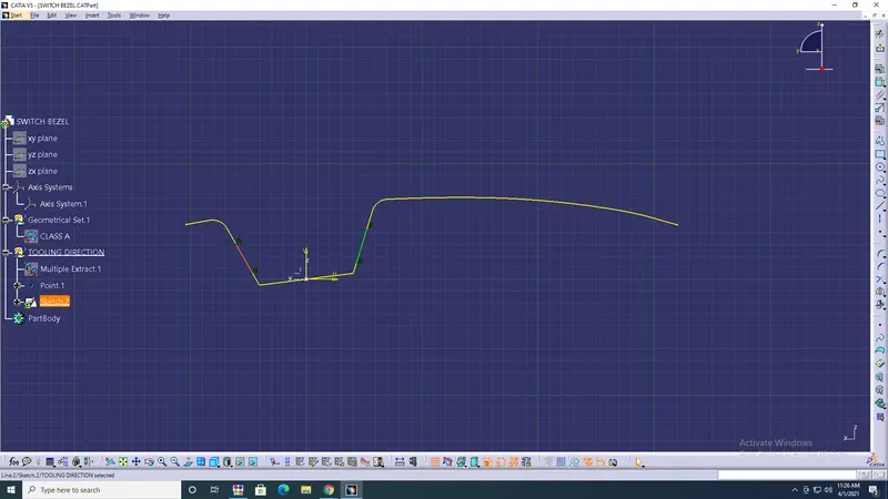
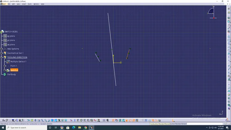
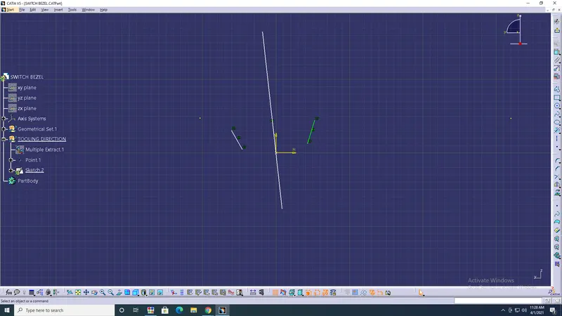
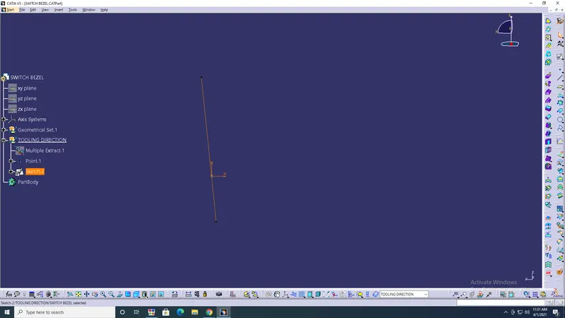
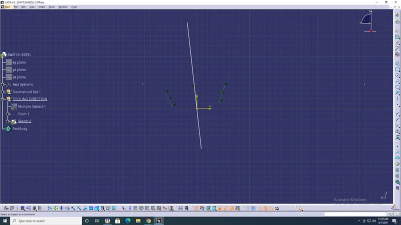
- Create other sketches> intersect the ZX axis with class A surface> draw the lines with a 5degree angle> bisect sketch1&2 in vertical axis> ok.
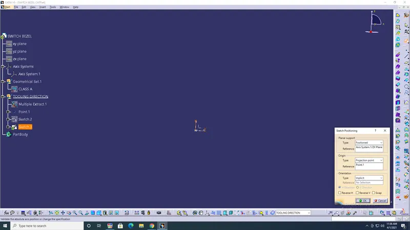
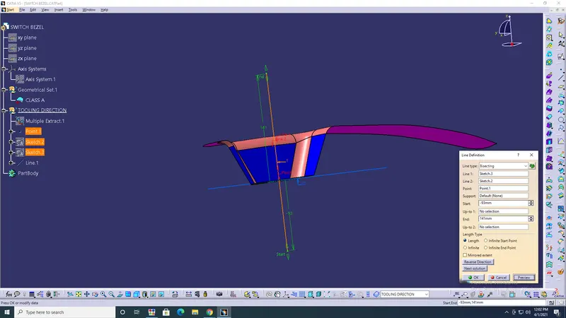
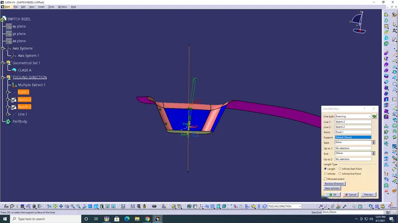
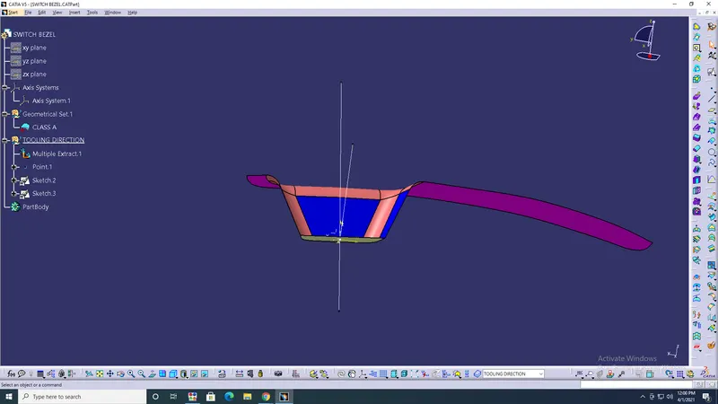
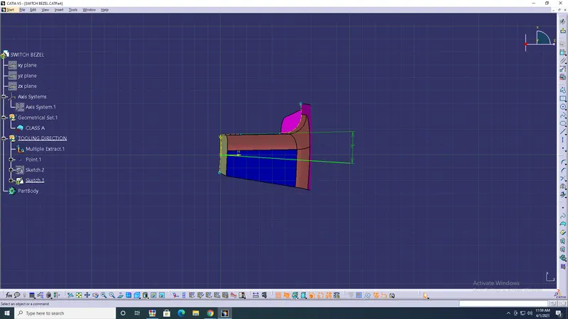
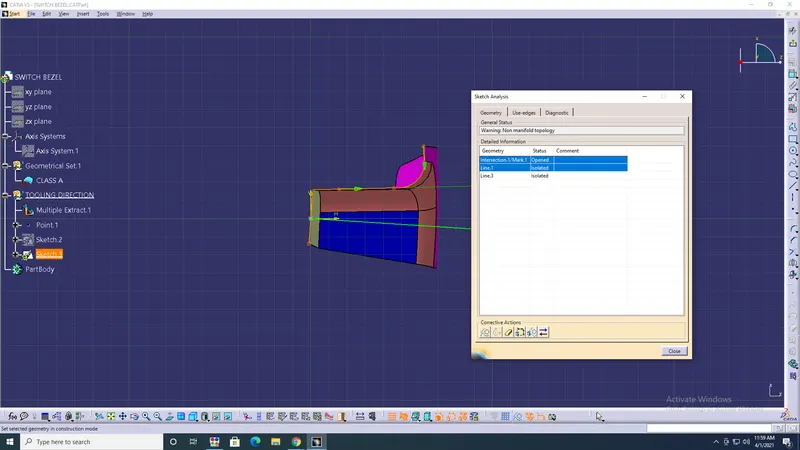
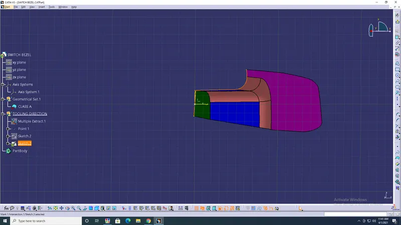
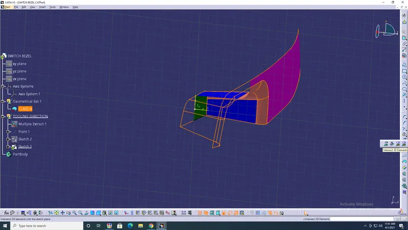
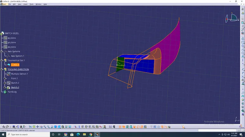
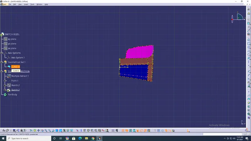
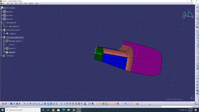
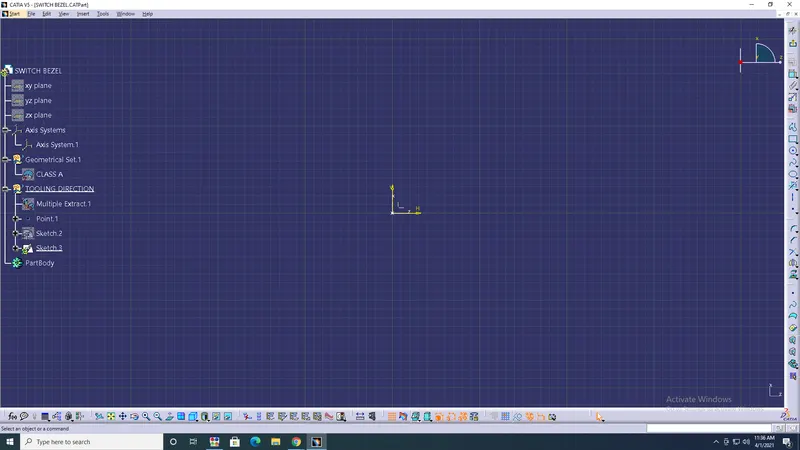
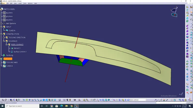
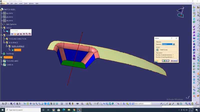
- create geometrical set> Bsurface> Bezel surface> extract> surface unitrim> hide extract> ok.
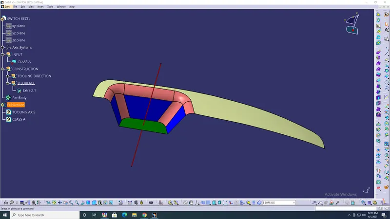
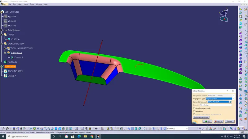
- Create> Geometrical set > Walls> Extract> Surface unitrim> Extrapolate> ok.
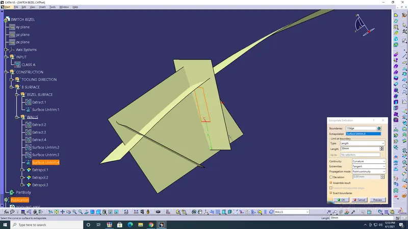
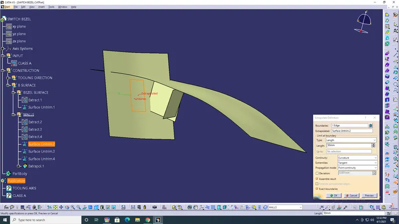
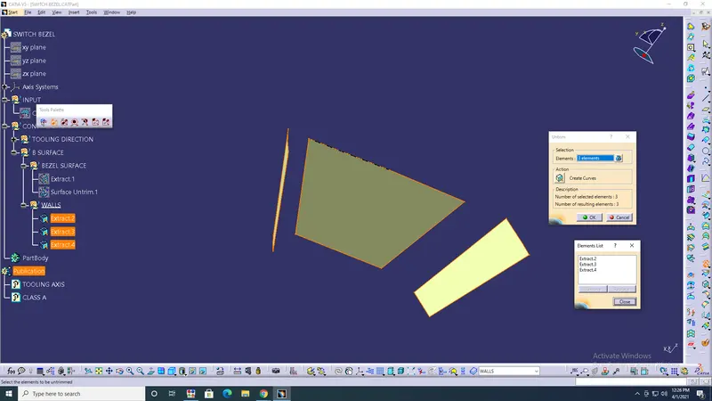
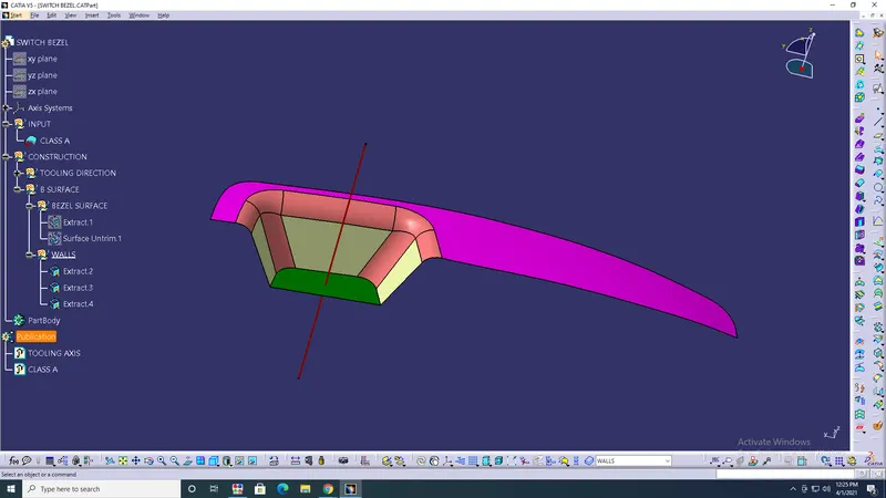
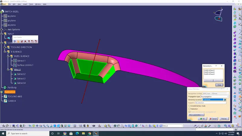
- Extrapolate all the surfaces with boundary> trim all the Surfaces required> ok.
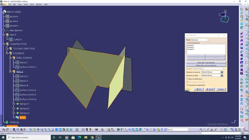
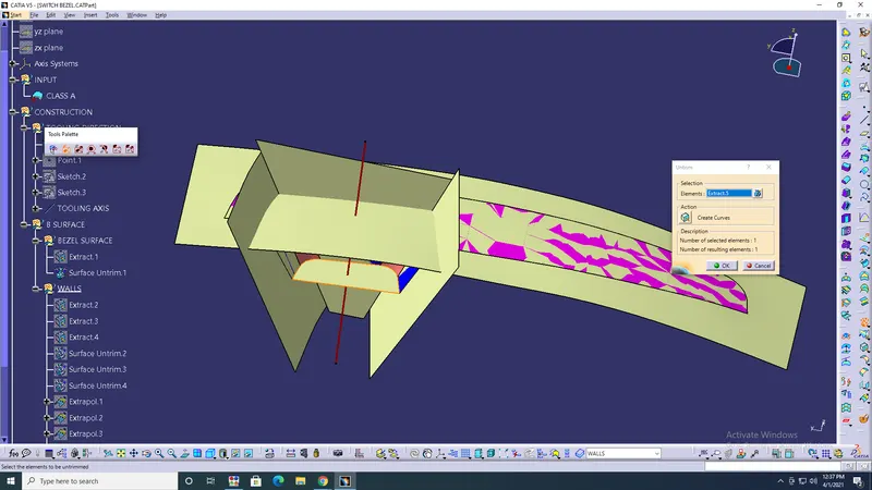
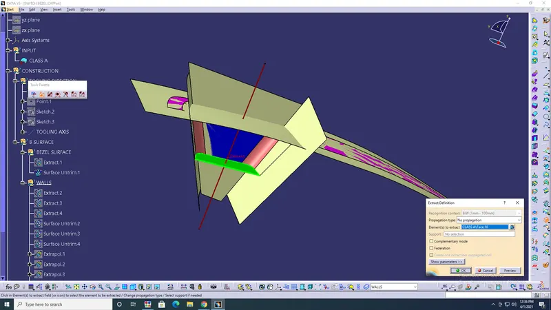
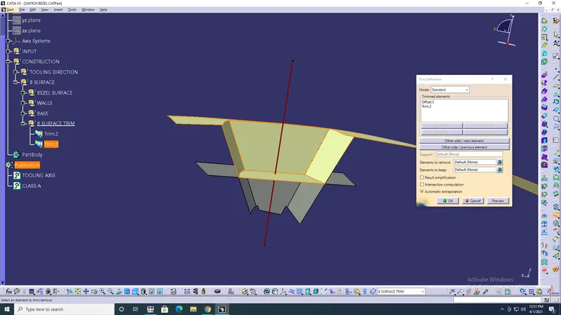
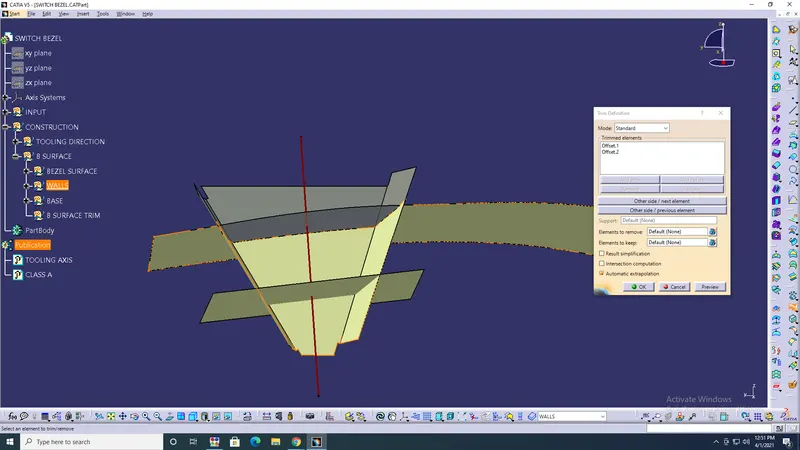
- Measure the radius of edge fillets with different extrac> Edge fillets> 11mm.
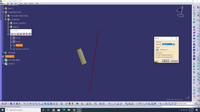
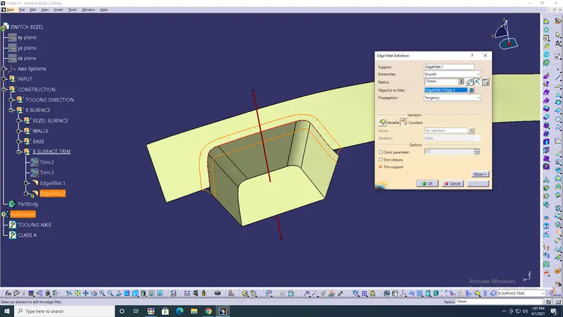
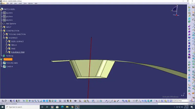
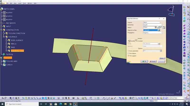
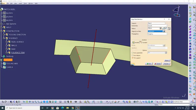
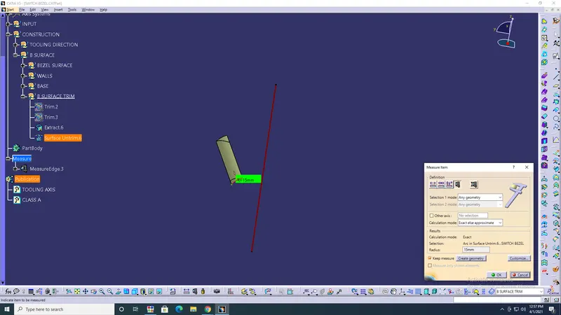
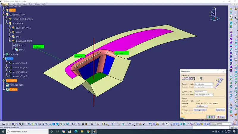
- Create class C surface> Create a boundary> Tangent> Class A surface> Sweep> Bounday> Tooling axis> Angle 3degree> ok> Curve smooth> Replace> Multiple Extract.
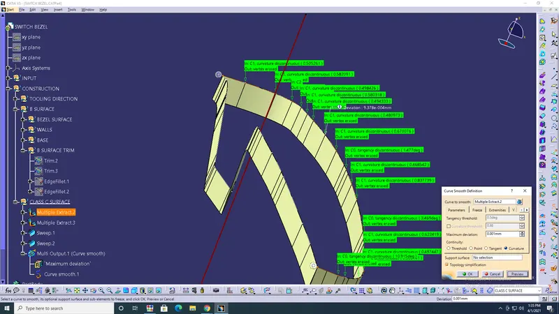
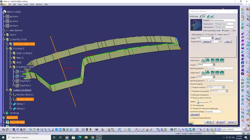
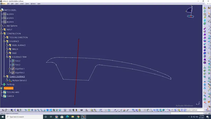
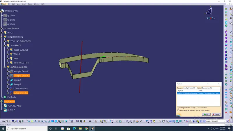
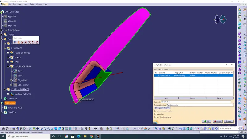
- Join> Trim & class A> Join & last operation> ok.
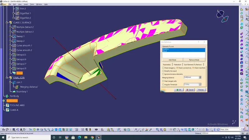
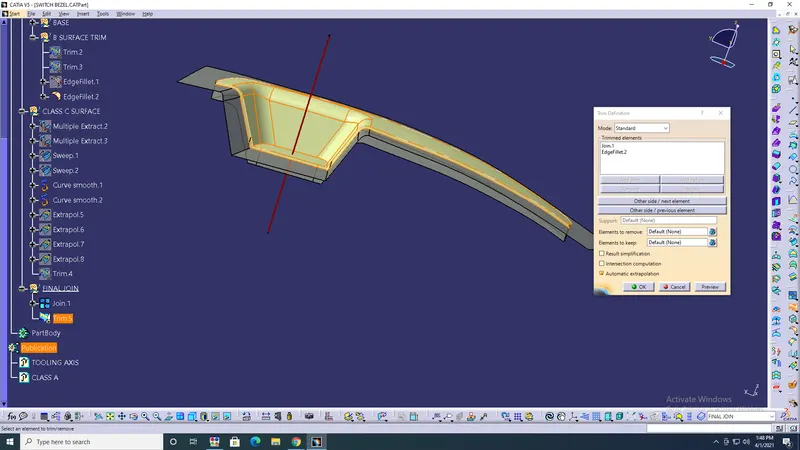
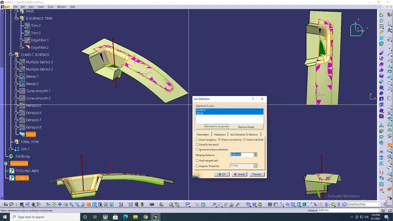
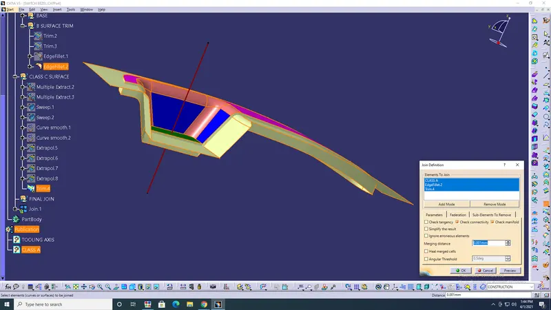
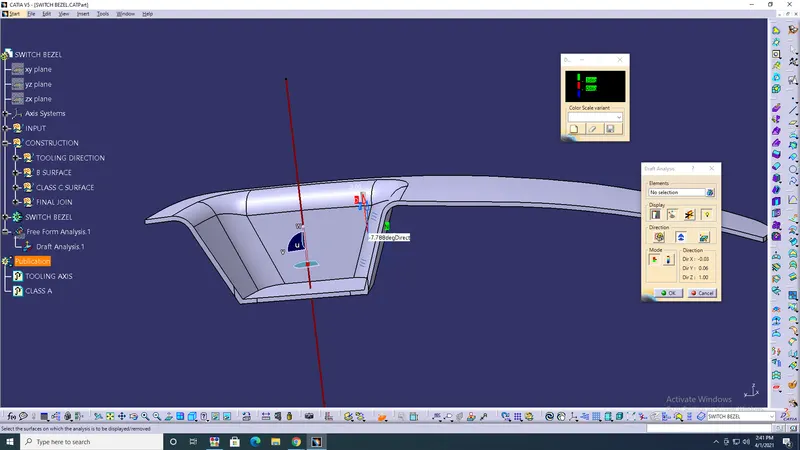
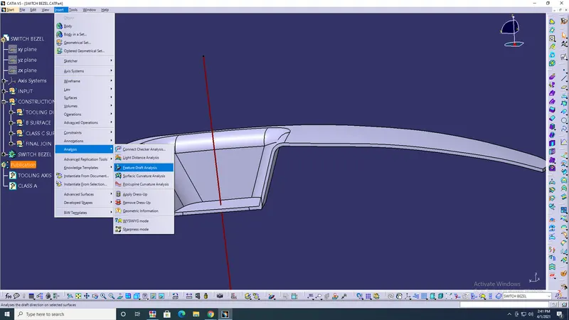
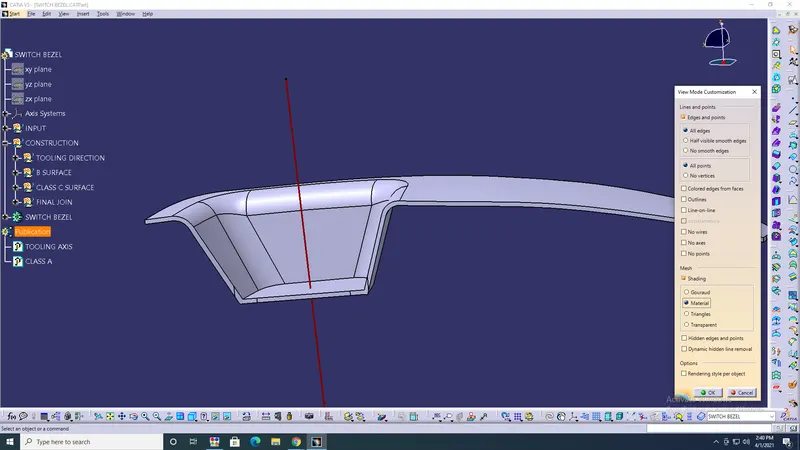
- Analysis> Draft analysis> Compass> place on tooling axis> draft should be 3degree's> create> closed surface> ok.
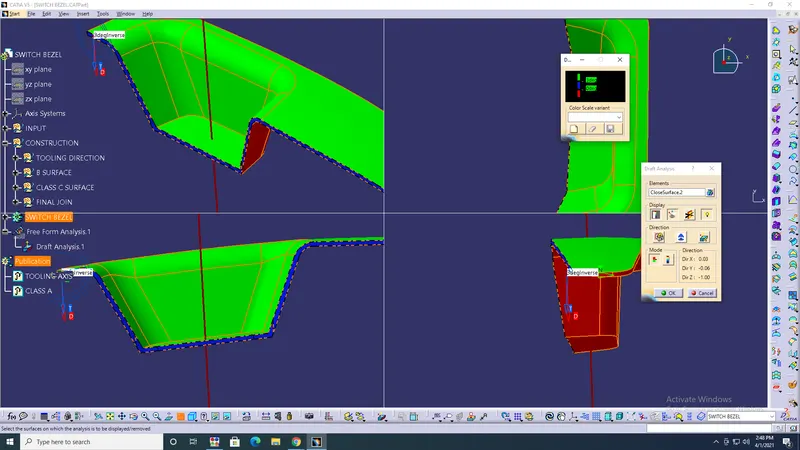
CONCLUSION: The switch bezel of surface created, with unitrims, extrapolate, join and the closed surface create, finally draft angle was done with 3degree's...