Week 8 - Challenge 2 - Base Bracket Design
AIM: To Create the Base Bracket Plastic component through the given Class-A surface. First, the tooling axis for the given Class-A Surface should be created to meet the draft angle requirements and perform the Draft analysis on the model.
SOFTWARE: CATIA v5.
PROCEDURE:
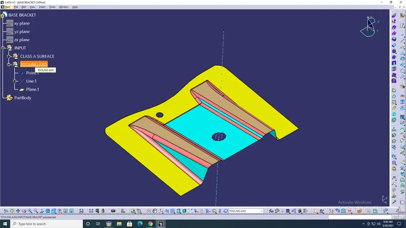
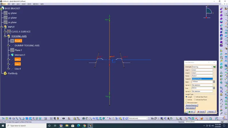
- Create a Tooling axis> Point> Plane> Line.
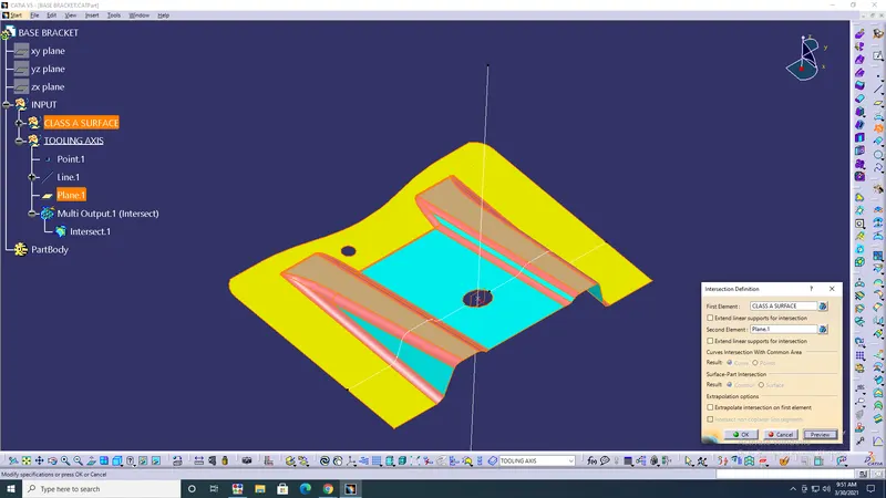
- Intersect> with Plane> ok.
- Line> Intersect/line> ok.
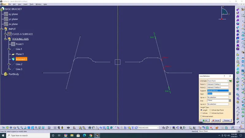
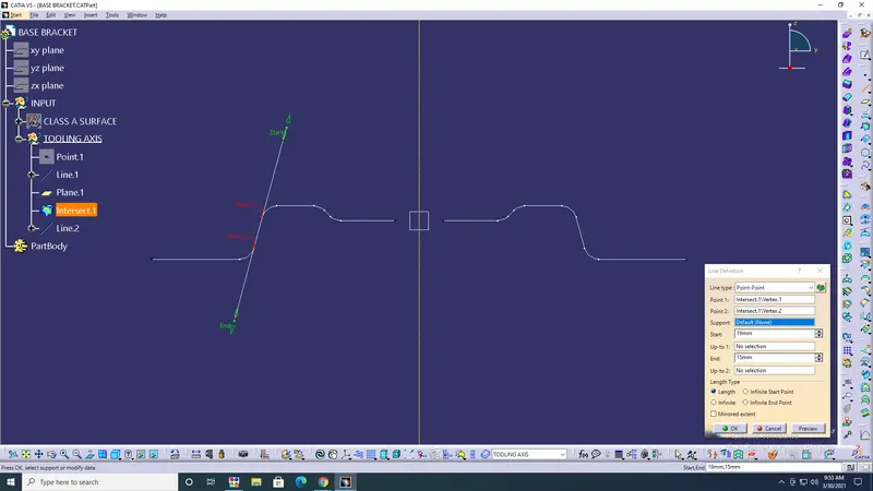
- Line> Bisect line1/2> ok.
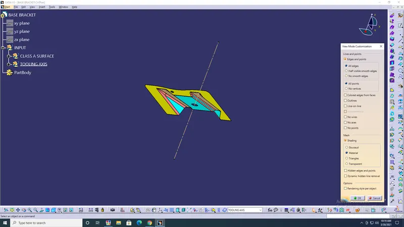
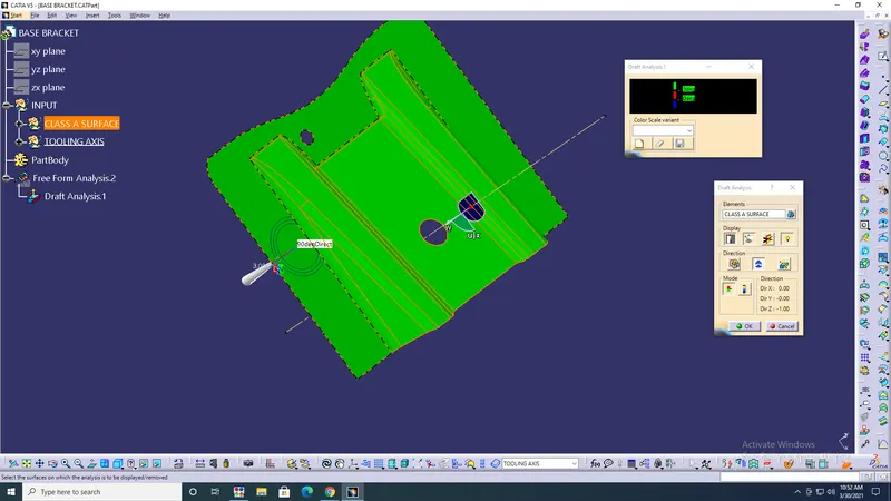
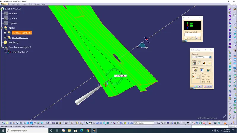
- Coustamize view parameters> material> Insert> Analysis> Feature draft analysis> Draft analysis should be 0 to 3degree> ok.
- Create geometrical set has B surface> Extract> Class A surface the face needed> No propagation> ok.
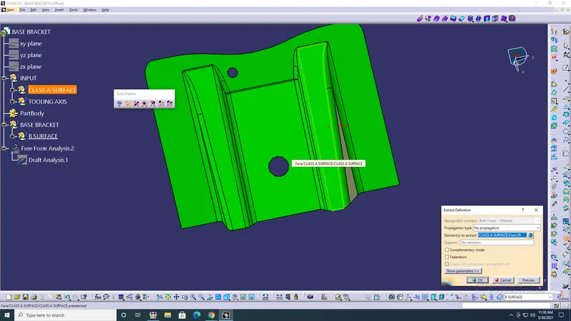
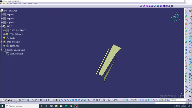
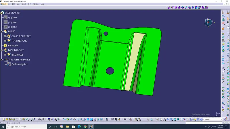
- Unitrm> Face's extract> ok.
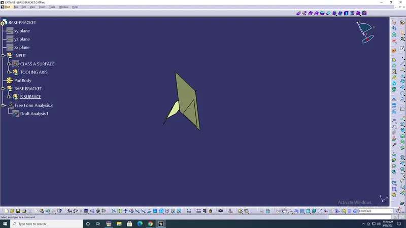
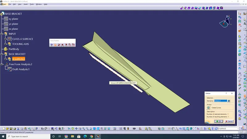
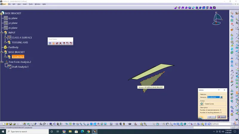
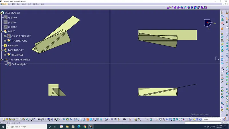
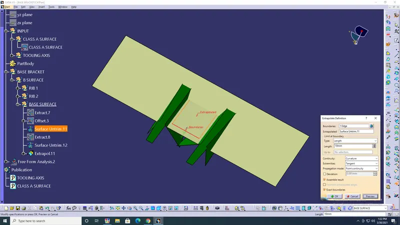
- Extrapolate> Boundary> Point continuity> Curvature> ok.
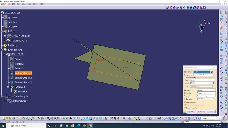
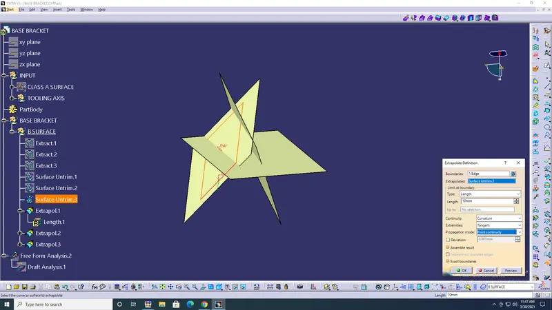
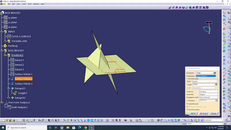
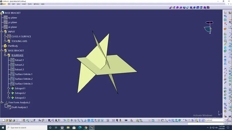
- Trim for rib1&2> Offset-2.5 rib1&2> ok.
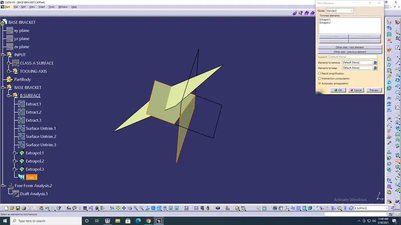
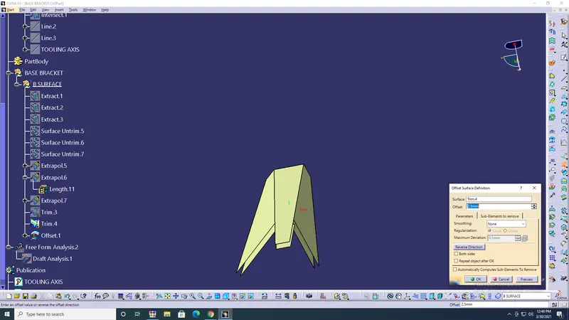
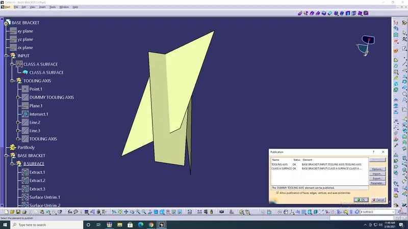
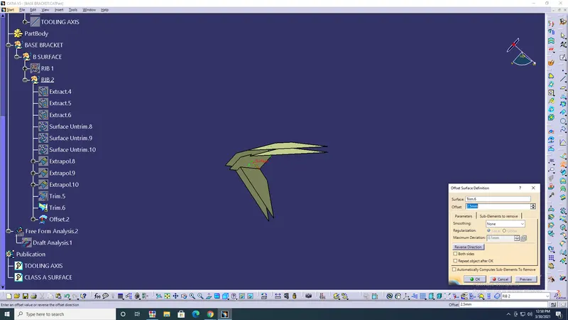
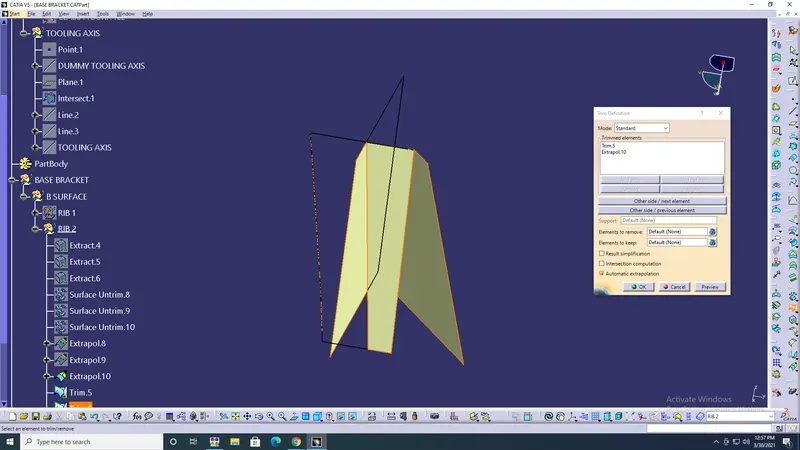
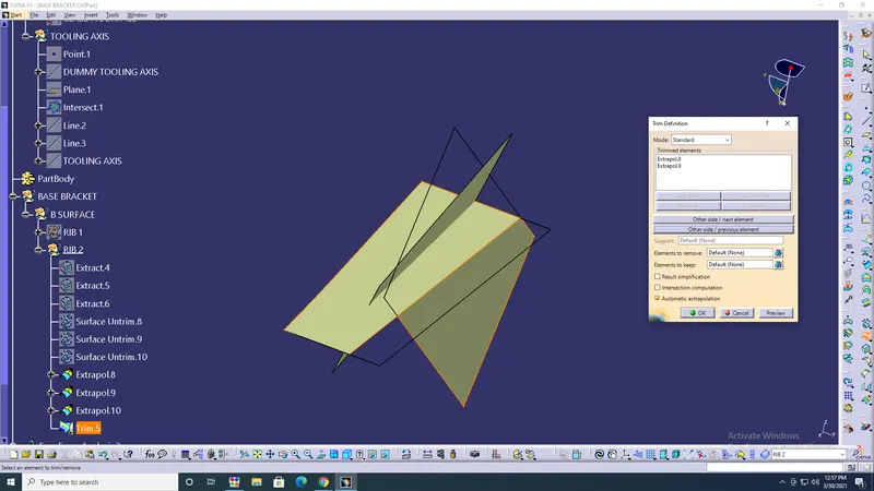
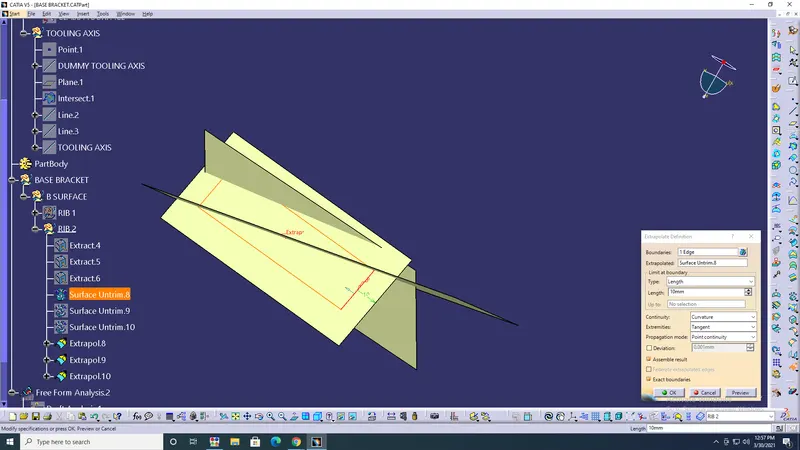
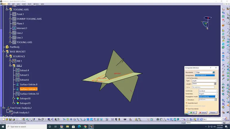
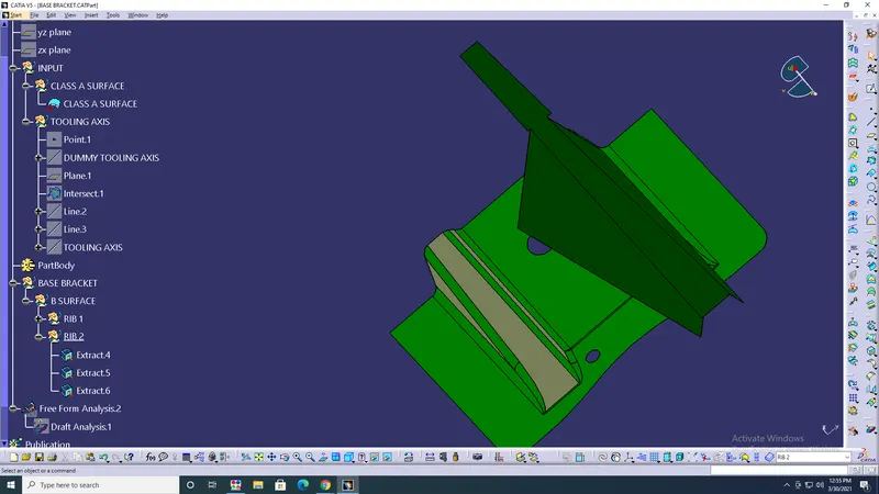
- Base> Offset> Unitrim> Extract> Extrapolate> Boundary> Point continuity> Curvature> ok.
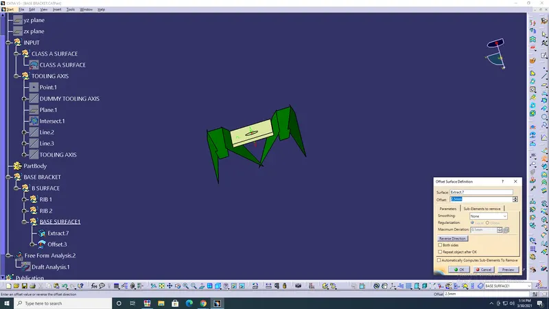
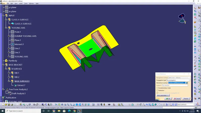
- Trim> Base> Ribs> ok.
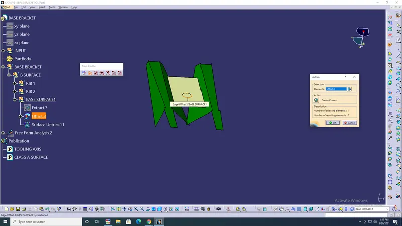
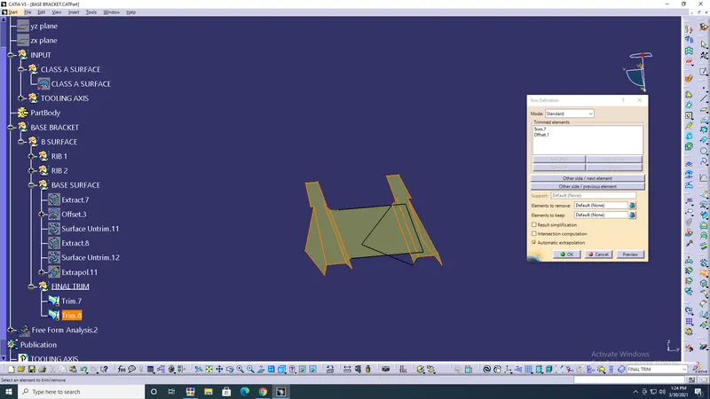
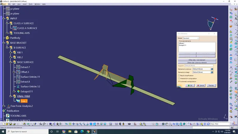
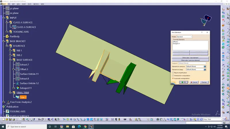
- Extrapolate based> Trim with trim 7> ok.
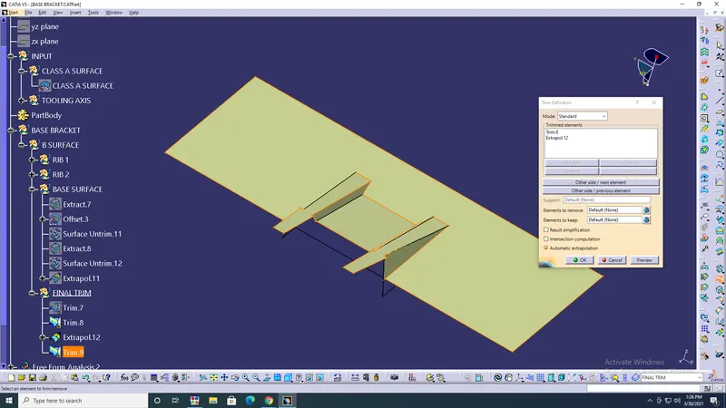
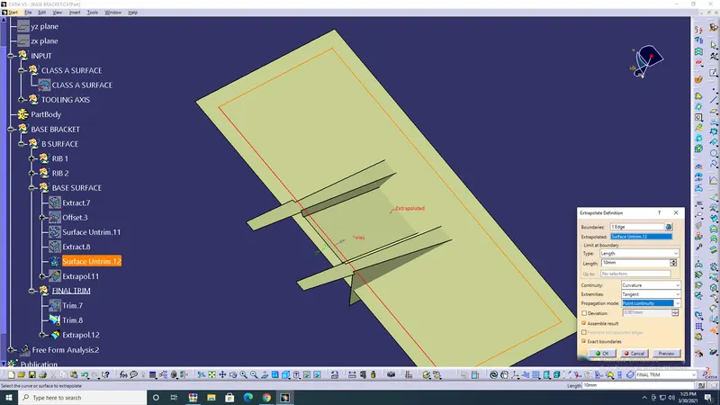
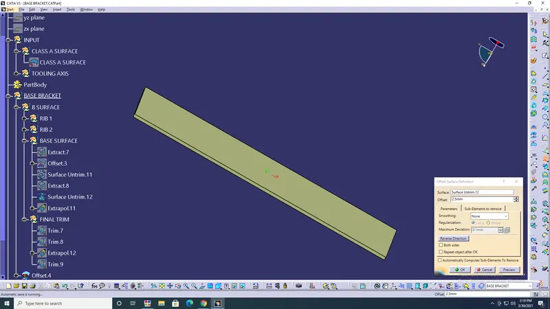
- Offset base> 2.5> ok.
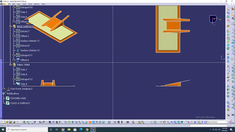
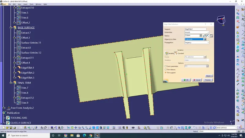
- Edge fillet> ok.
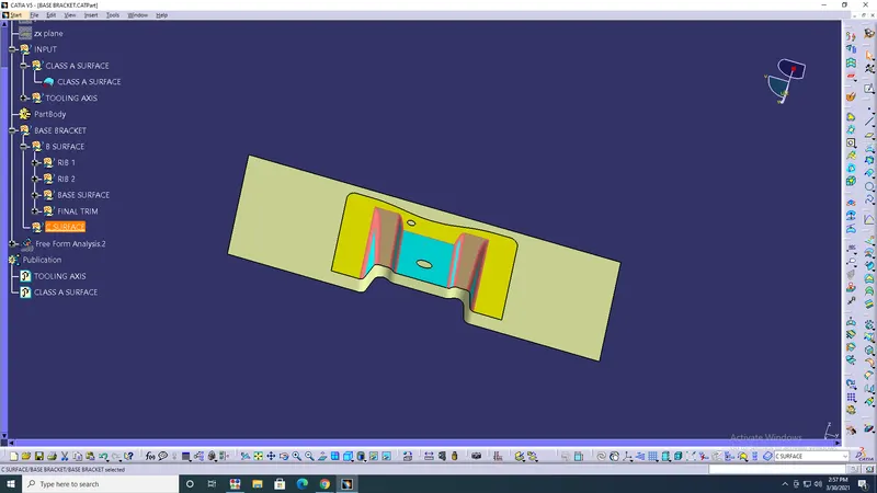
- Create a C surface.
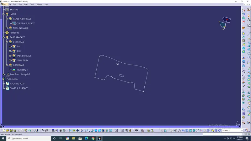
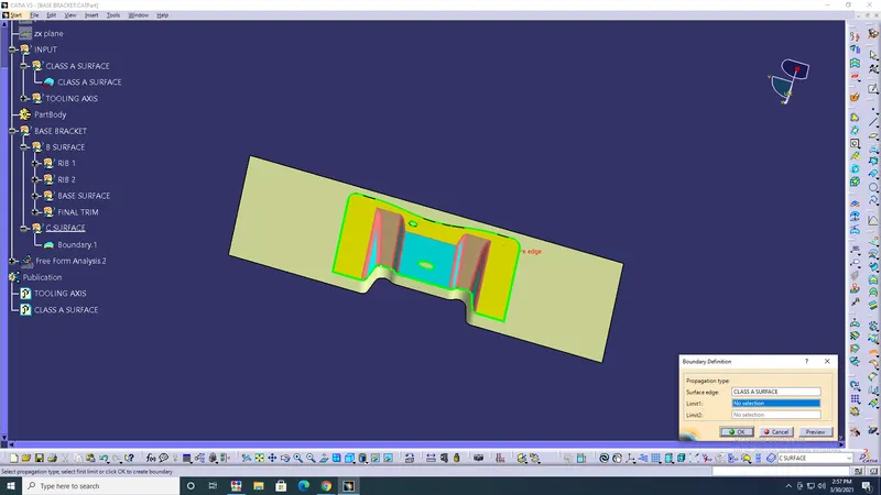
- Boundary> Class A surface> ok.
- Sweep> Line> Boundary> Draft angle> Angle 3degree> ok.
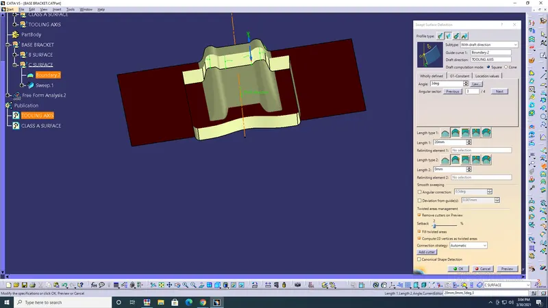
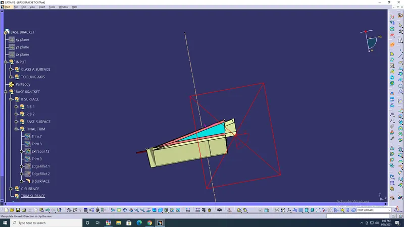
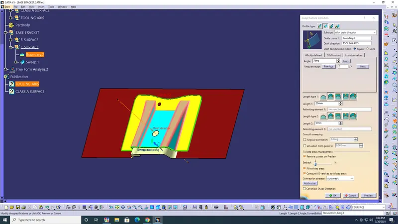
- Boundary of holes> Line> Angle 3degree> ok.
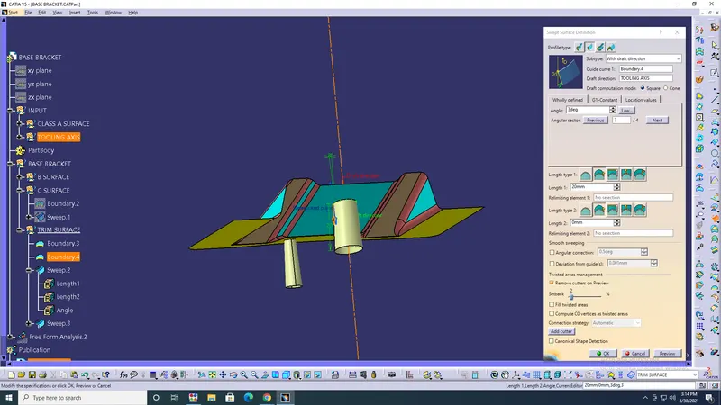
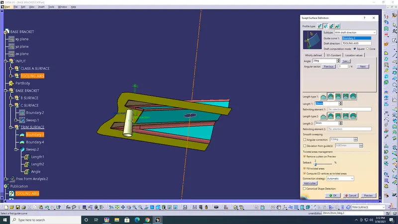
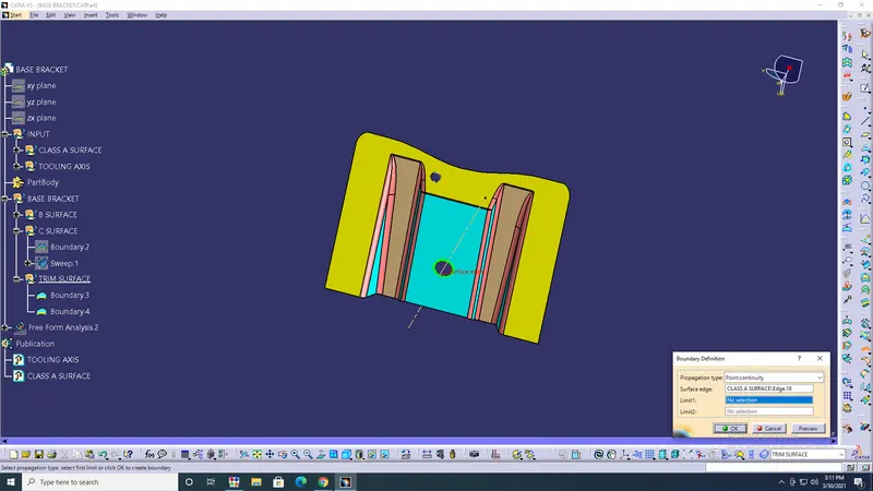
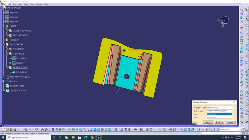
- Trim> Sweep1 & Sweep2> Base Surface> ok.
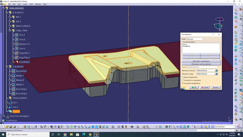
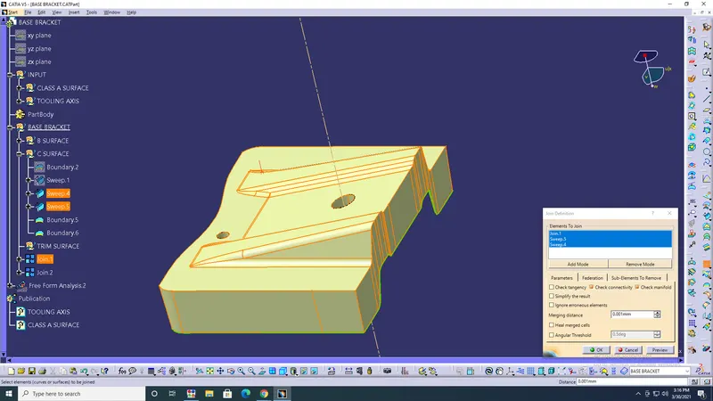
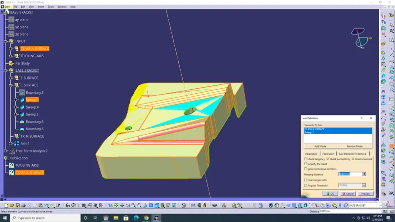
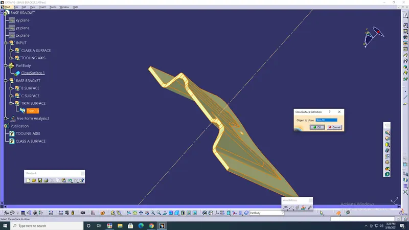
- Closed surface> Hide> Trim> ok.
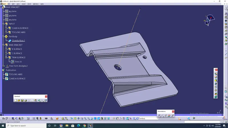
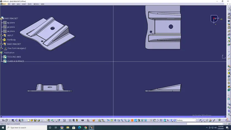

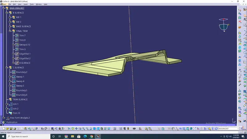
RESULT: The class B&C surfaces are created with class A surface reference, and the draft analysis are performed.