Week 9 - Project - Master Section Development
AIM: To Design a B pillar of the car using a given input surface.
SOFTWARE: CATIA v5.
COMMAND: Tooling axis> Thicksurface> Sketch> Surface> Boolean> Draft analysis.
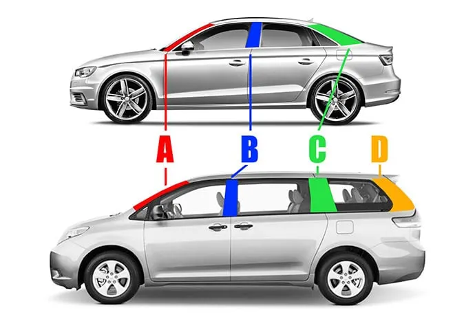
B pillar The vertical roof support structure is located between a typical vehicle's front and rear doors. It corresponds with the A-pillar situated on either side of the windshield at the front of the car and the C pillar, which sits on either side of the rear window on a typical sedan.
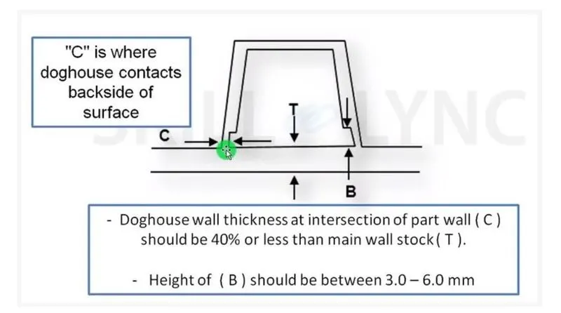
The DOG HOUSE is an engineering feature used in the plastic trim design. Dog houses are used as supporting features. Dog houses are subjected to draft analysis to prevent breakage of the component during ejection from the mould cavity. Dog house and other engineering components are built on B-surface.
- 4-way means preventing movement at two-axis (+X, -X, +Y and -Y) on the plane. Generally, you have a cylindrical pin on the fixture and a circular hole at the workpiece part.
- 2-way means preventing movement only at one axis on the plane. And generally, you have a cylindrical pin on the fixture and a slot hole at the workpiece part.
We generally use one 4-way and one 2-way at the same time. We need freedom of movement because the distance between pins at the fixture or the holes at the workpiece might not be entirely accurate.
- DEGREE OF FREEDOM:
DOF of a point is the number of independent coordinates required to define the position and orientation of an issue.
Rib design rule:
- Rib draft angle- 0.5deg
- Rib fillet radius- 0.25mm

PROCEDURE:
- Join> Tooling axis> Draft analysis.
- Create the main tooling axis to avoid problems in injection moulding.
- Join all class A surfaces.
- As well as do draft analysis.
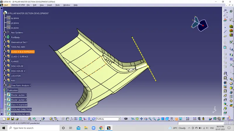
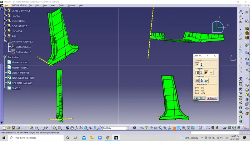
Fig: 1&2.
- Improve class B surface> offset> class A surface.
- Improve all the joins and offset to 2.5mm for A surface output.
Fig: Class B improved.
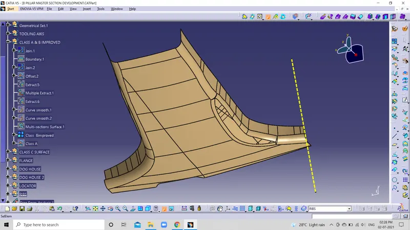
Fig: Class A
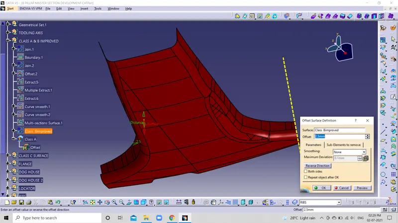
- Class A> Multiple extract> Boundary> Sweep> Trim> No gaps> Offset> Join with class B> Edge fillet.
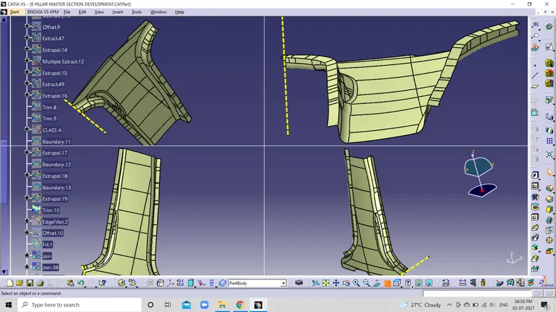 Fig: 1
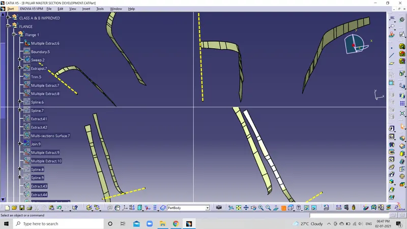 Fig: 2
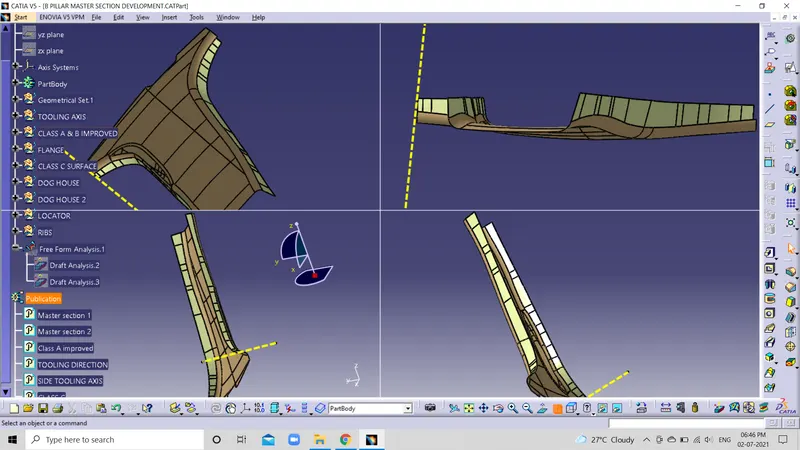 Fig: 3
 Fig: 4
- Class A> Multiple extract> Sweep> Extrapolte> Join> Trim> Class B with Class C> Trim> Class C with Class A.
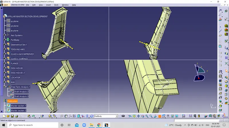 Fig: 1
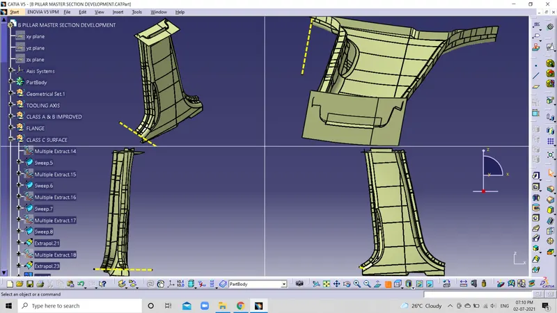 Fig: 2
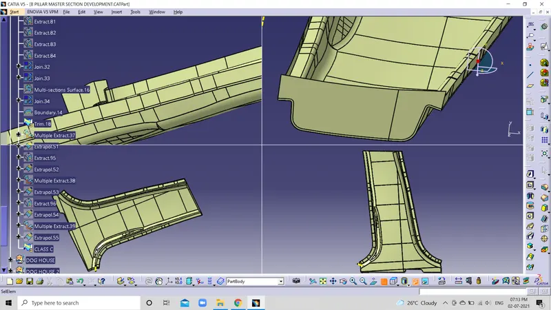 Fig: 3
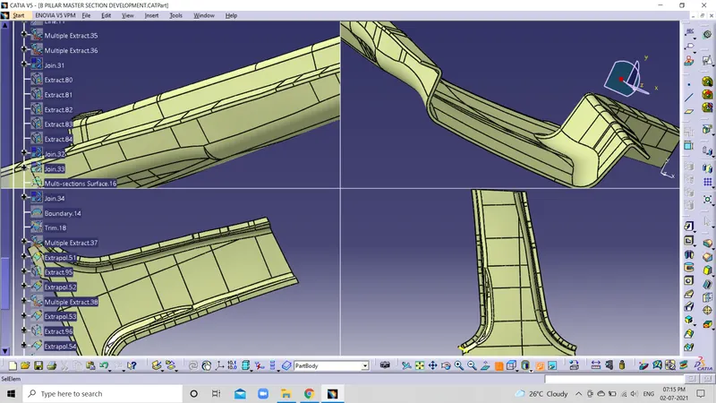 Fig: 4(Class-C)
- Draft analysis> Closed surface.
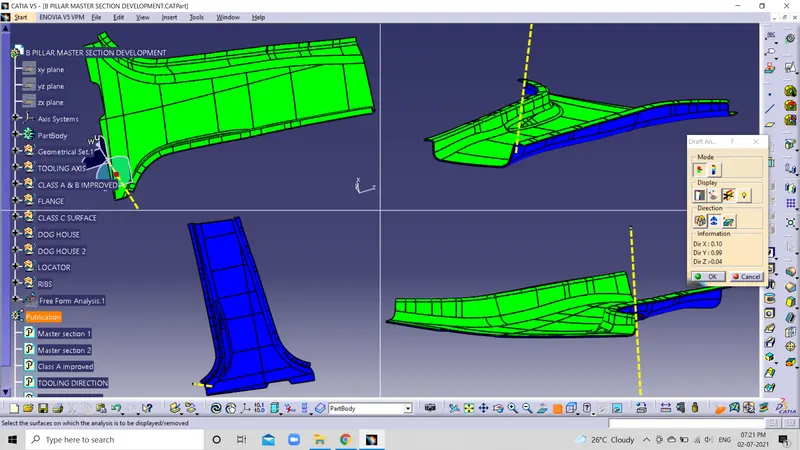 Fig: 1
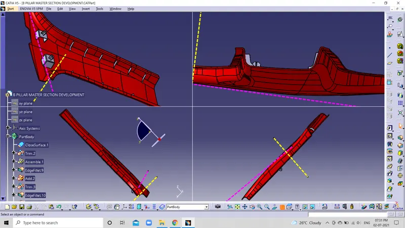 Fig: 2
- Side tooling axis> Dog house> Select surface> Sketch> Draw C section> Extract> Extraplote> Thicksurface> Trim> Translate> Rotate 180deg> Boolen> Closed surface> Unitrim with part body> Edge fillets> Draft analysis.
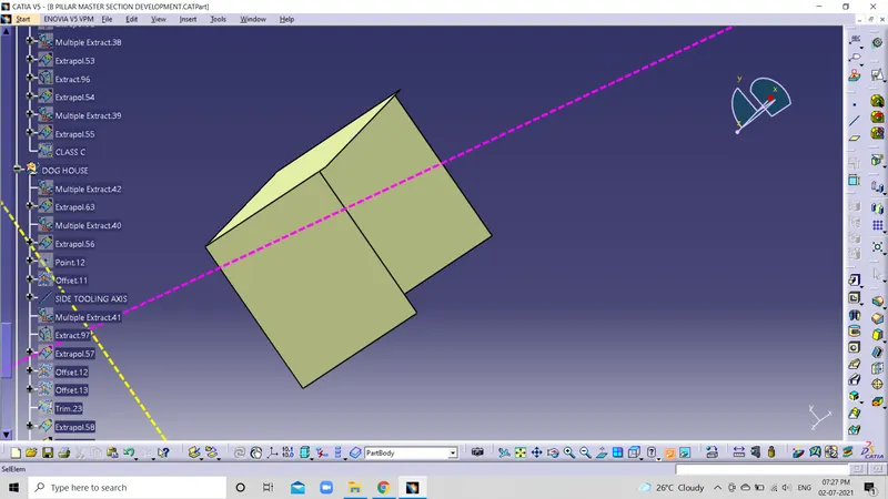 Fig: 1
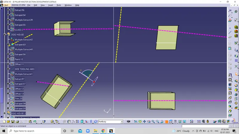 Fig: 2
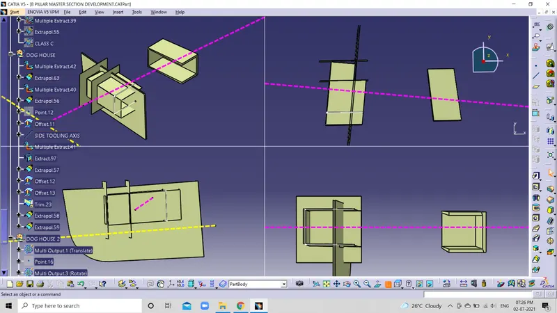 Fig: 3
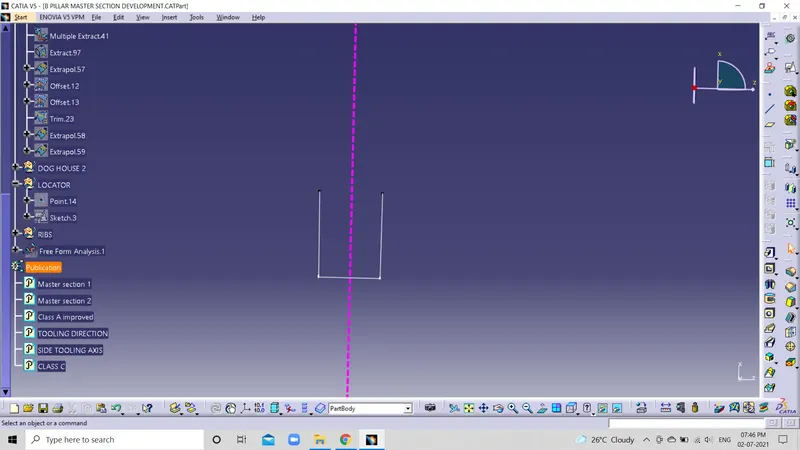 Fig: 4
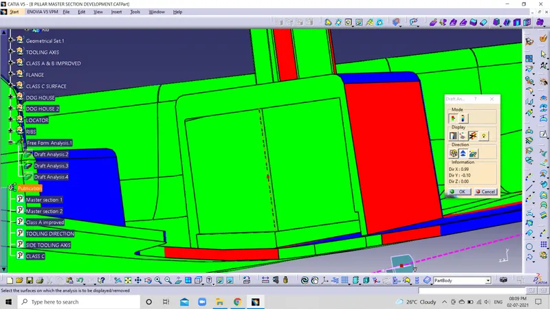 Fig: 5
- Sketch> Locator> Extract> Extrapolate> Thicksurface> Chamfer 5mm, 45deg> Trim> Closed surface> Add> Unitrim.
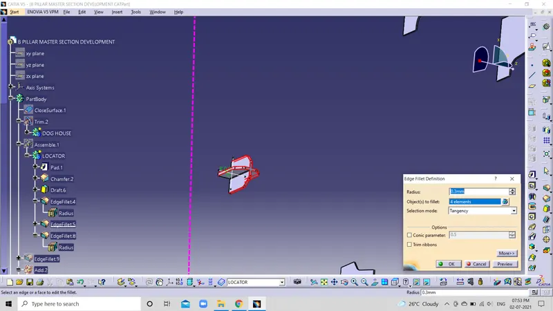 Fig: 1
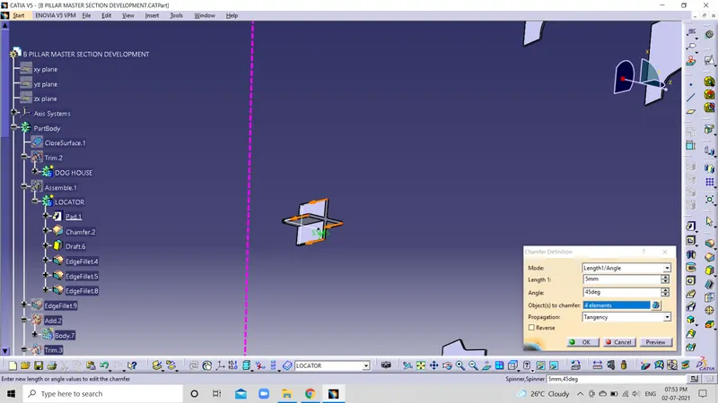 Fig: 2
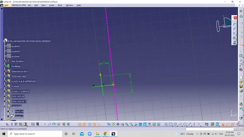 Fig: 3
- Rids> Sketch> Line> Extract> Thicksurface- 0.4,0.4> Split> Class B Extract> Offset 10mm> Unitrim> Translate> Edgefillet> Draft> Translate> Point to Point.
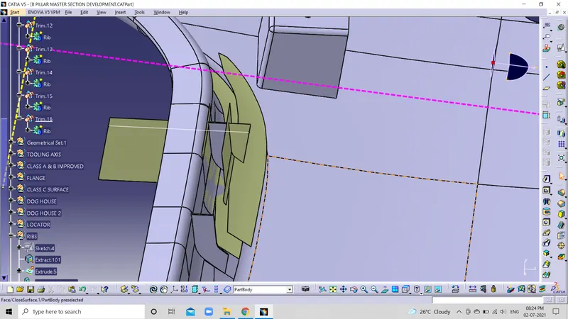 Fig: 1
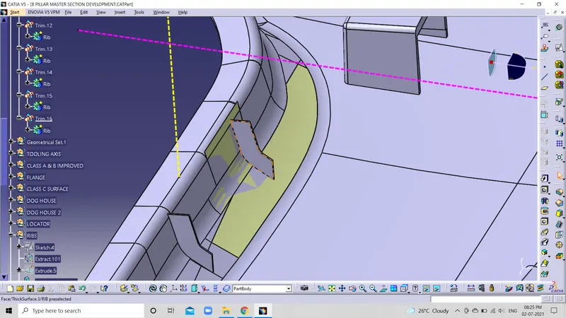 Fig: 2
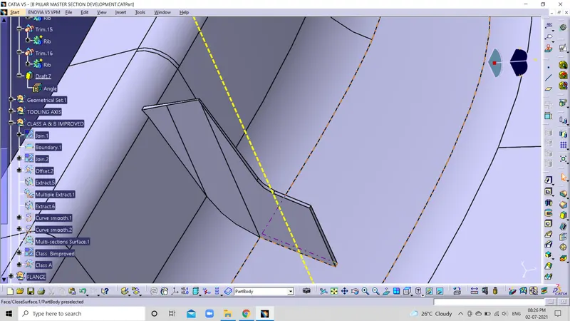 Fig: 3
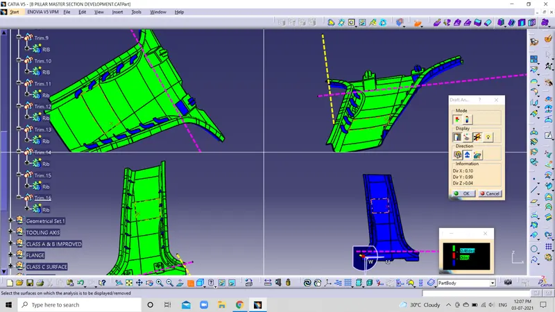 Fig: 4
RESULT:
- Class B improved by joining all the master sections.
- The nominal draft angle is 3deg; for engineering futures draft angle is 0.5deg.
- A closed surface creates the closed body in part body design.