Week 11 - Final project Door Trim
AIM:
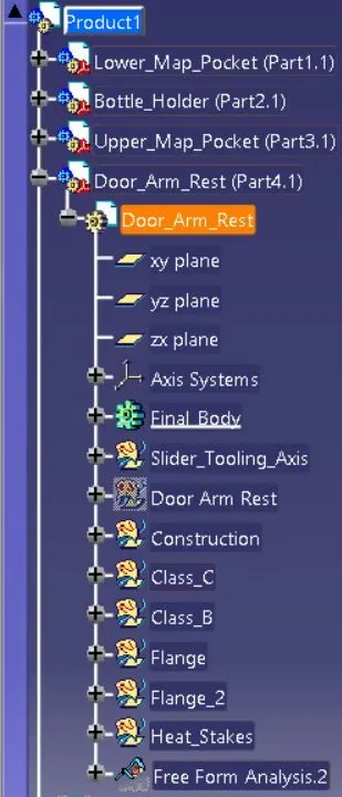
- To design and development of the car interior door trim with CATIA-V5. Using the class A surface and master section as inputs, we created the Tooling axis, CLASS-B surface, CLASS-C surface, Flanges, Dog House, Push Clips, and Heat Stakes.
- The draft analysis is also be performed using the Tooling and Side tooling axis.
PLATFORMS USED:
- Generative Shape Design.
- Part Design.
- Assembly Design.
OUTPUT REQUIRED:
- Class A surface extraction.
- Tooling axis, Side core axis.
- Creation of Class B surface.
- Creation of Class C surface.
- B side features.
- Draft analysis.
COMMANDS:
- Draft
- Edgefillet
- Extrapolate
- Extrude
- Join
- Line
- Point
- Revolve
- Sketch
- Split
- Thickness
- Translate
- Trim
THEORY:
- Door panels serve as the interface between the interior of the car and the inner workings of the door and between vehicle occupants and the door. They are expected to meet a variety of design specifications regarding safety, aesthetics, and functionality.
MASTER SECTION:
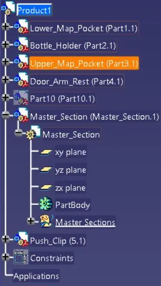
- Master sections guide design requirements that decide the component packing after technical [Styling, Concept & Class-A] Surface.
OVERVIEW OF DESIGN LIFE CYCLE:
- CLASS-A SURFACE: Class-A surface is created by a computer-aided industrial design application. Class-A surface modellers are called Digital Sculptors in industry.
- FEASIBILITY CHECK: Design feasibility is a validation process that looks at how well a design delivers to requirements, Objectives and goals. This can be a lightweight evaluation process or an in-depth study that tests parts of the design with techniques such as prototyping.
- CONCEPT VALIDATION: With concept validation, you can make data-driven decisions on whether you should commit to the design or development process.
- NEW PRODUCT DESIGN[NPD]: The process of bringing an original product idea to market. Although it differs by industry, it can essentially be broken down into seven stages: ideation, research, planning, prototyping, sourcing, costing, and commercialisation.
PROCEDURE:
CLASS-A & MASTER SECTION EXTRACTION
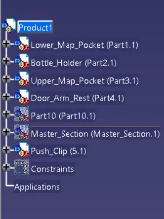
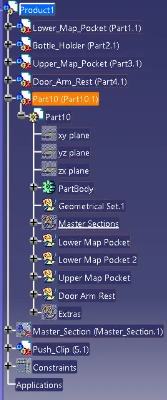
The first step is to join the class A surface of the Door Trim panel into different Geometrical sets as follows.
- Bottle Holder
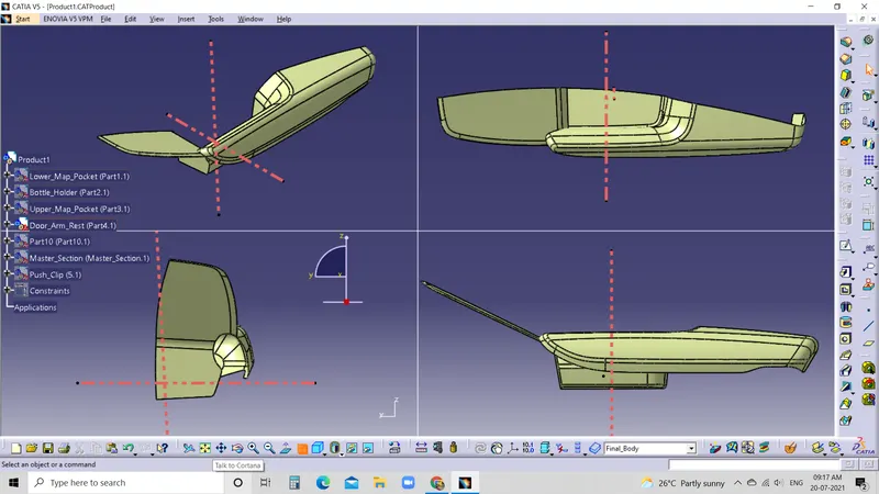
- Door Arm Rest
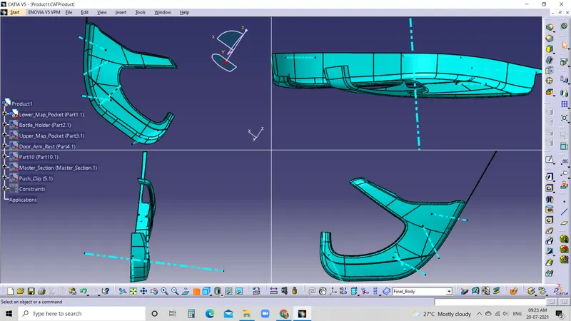
- Lower Map Pocket
- Upper Map Pocket
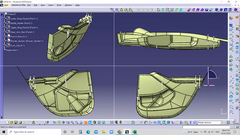
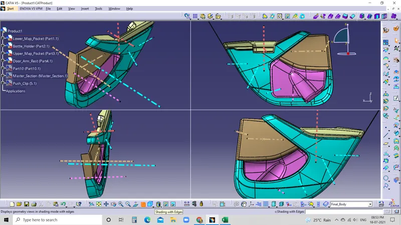
We have to ensure that the class A surface for each part has to be joined with merging 0.001mm has a single profile geometrical set.
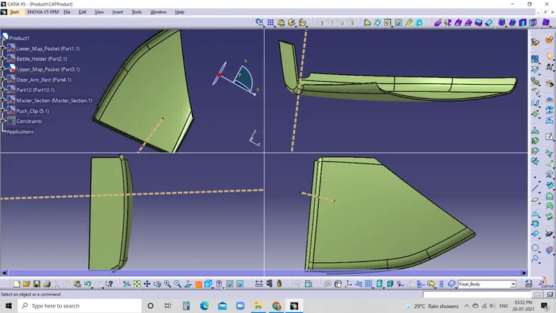
- Class A & Master section
Before Join
After Join
CLASS-A DOOR ARMREST
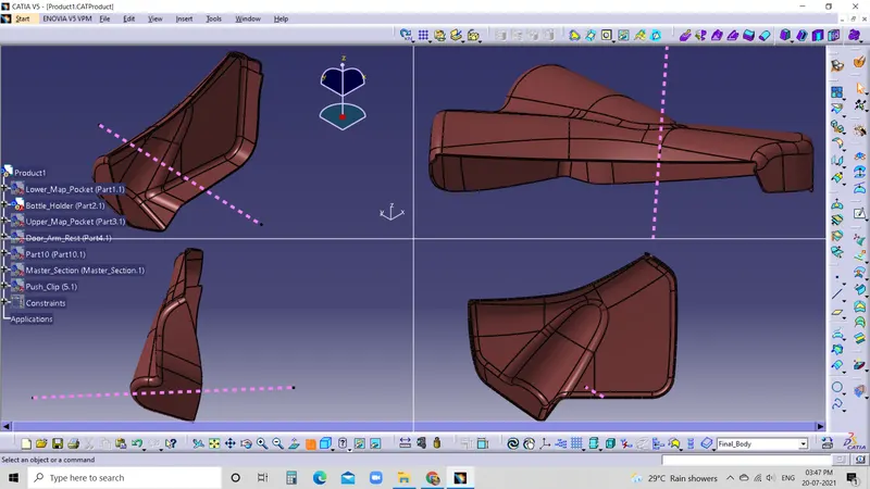
CLASS-A LOWER MAP POCKET
CLASS-A UPPER MAP POCKET
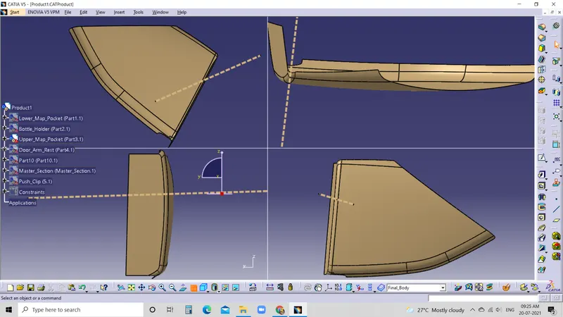
CLASS-A BOTTLE HOLDER
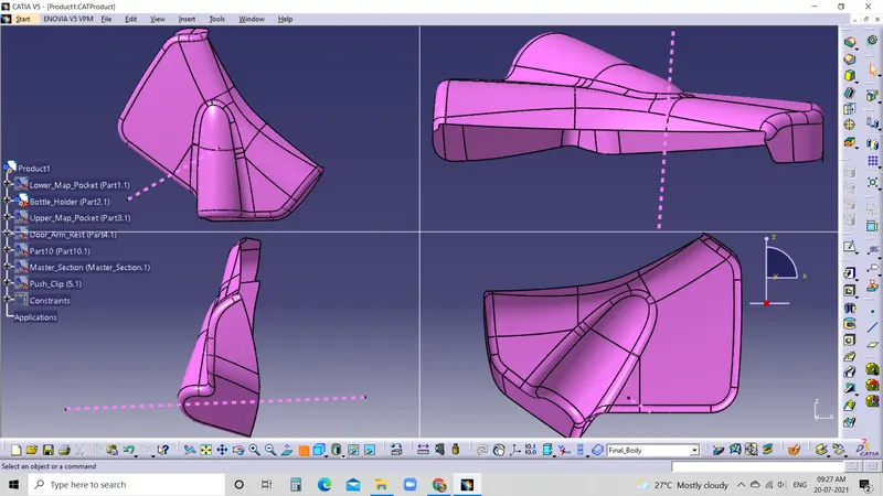
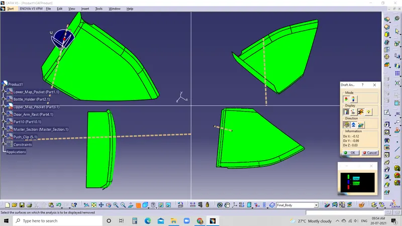
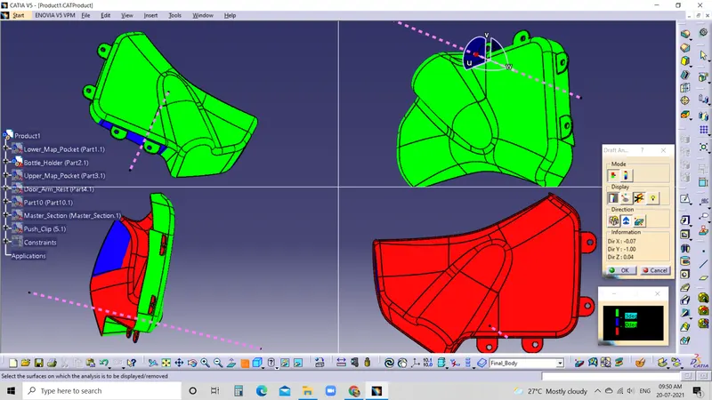
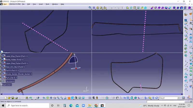
TOOLING AXIS AND DRAFT ANALYSIS OF CLASS-A SURFACE
TOOLING AXIS:
- The direction in which the mold or core and cavity opens is the tooling axis.
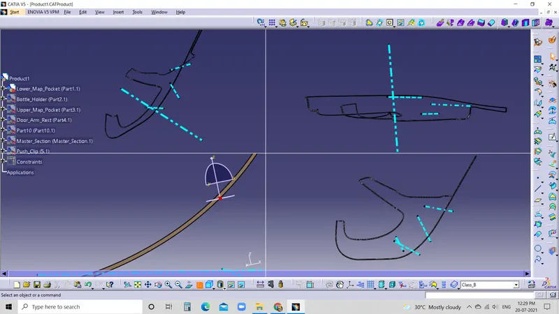
- Using the intersection, lines will be created along inclined walls. These lines are used to create the tooling axis by the bisection method, where the two points and lines will be selected as inputs.
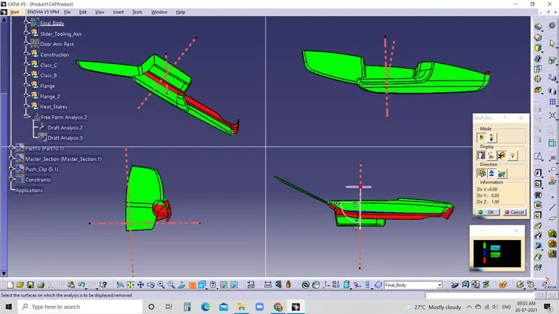
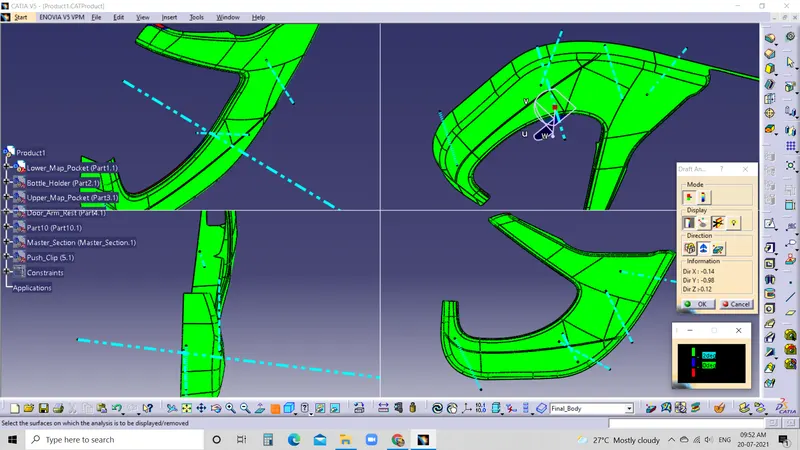
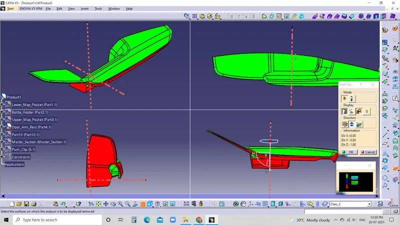
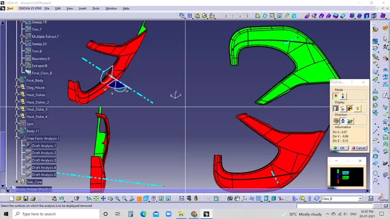
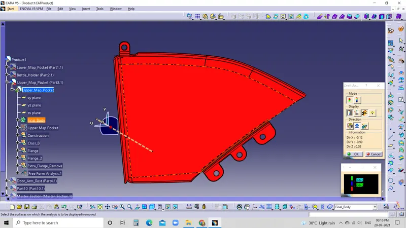
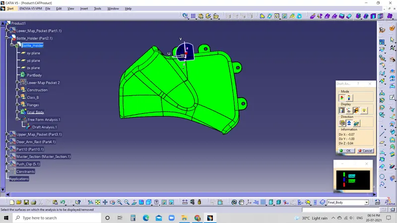
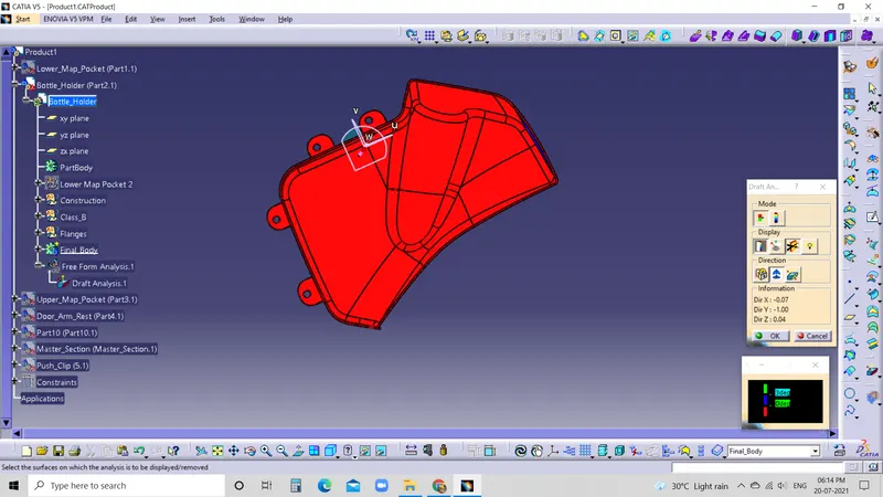
DRAFT ANALYSIS:
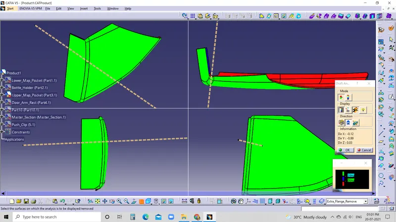
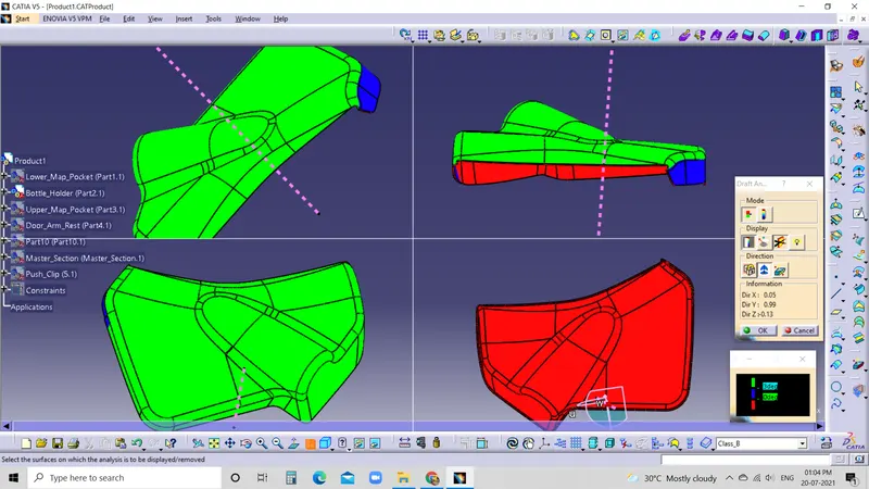
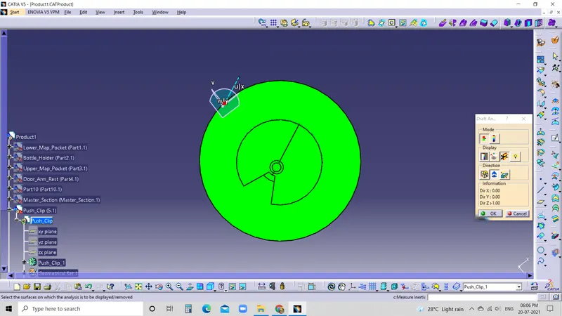
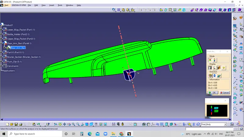
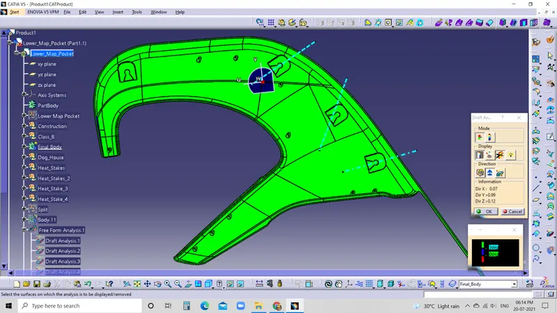
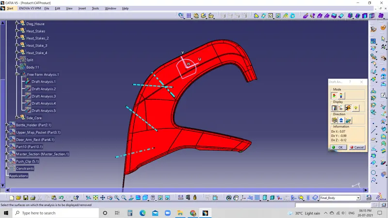
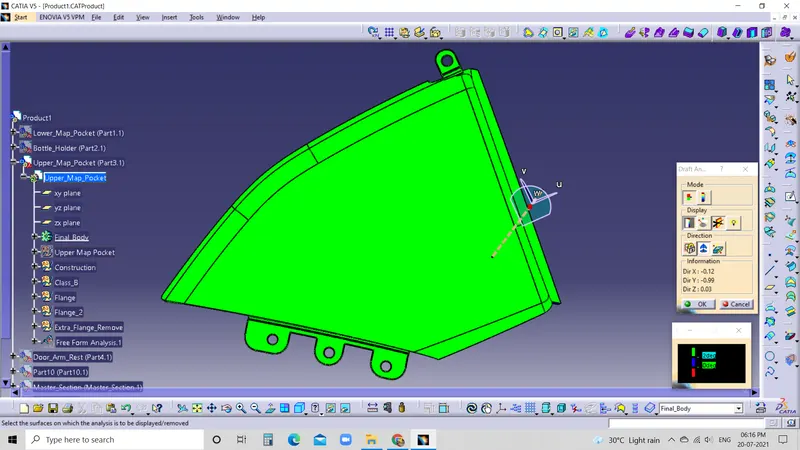
- The Draft Analysis command enables you to detect if the part you drafted will be easily removed. This type of analysis is performed based on colour ranges identifying zones on the analysed element where the deviation from the draft direction at any point corresponds to specified values.
CREATION OF CLASS-B SURFACE:
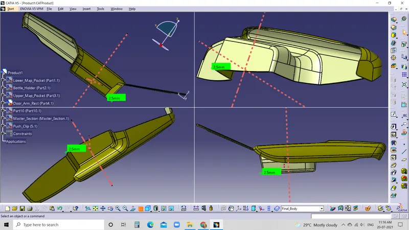
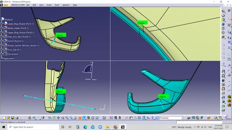
What is a Class B surface?
- Class B surfaces are the secondary surfaces that you can see sometimes but are less important, such as the inside of your glove box, ashtray, door panel etc.
- Here we create class-B with an offset of class-A surface to 2.5MM.
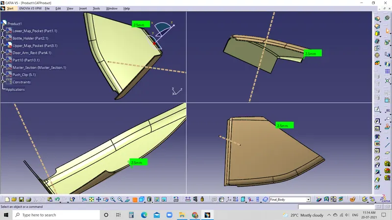
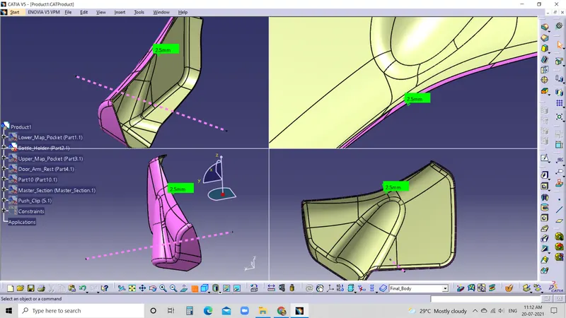
CREATION OF CLASS-C SURFACE
What is a Class C surface?
- In which the Customer demands the highest quality appearance. Class C is often specified for interior surfaces not readily visible, surfaces covered by another part when assembled, or surfaces that the Customer feels do not need to meet a high cosmetic finish.
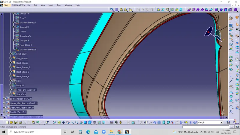
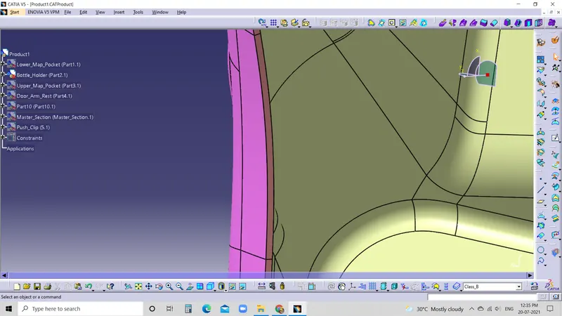
- The commands we use here are Sweep, Blend, Multisection, Extrapolate and Extract.
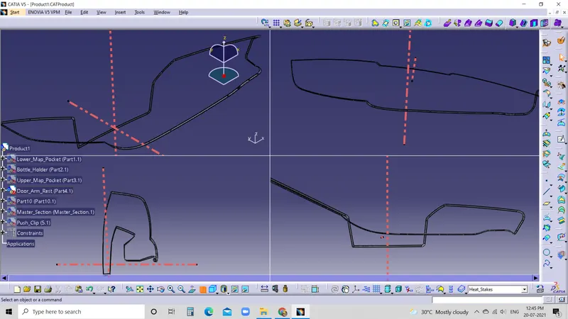
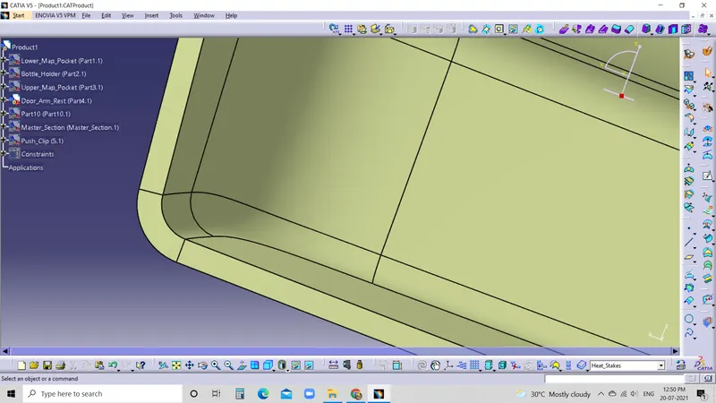
DRAFT ANALYSIS ON FINAL SURFACE
CLOSED SURFACE'S
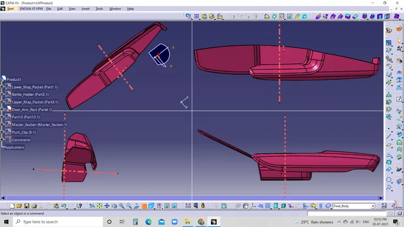
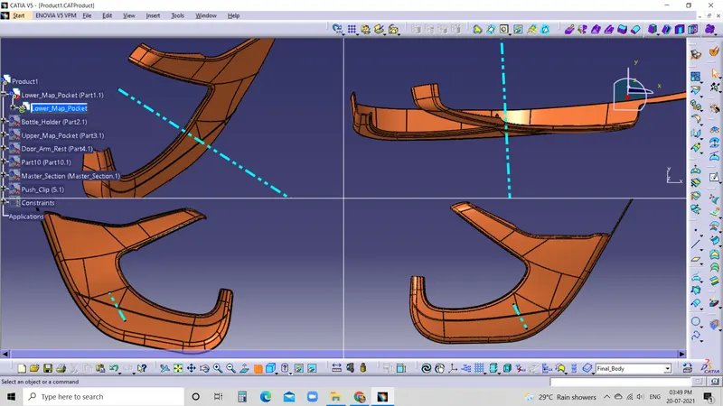
Creates a solid body from a closed set of surfaces
- First of all, join all the surfaces to which the solid has to be created.
- Go to Part design workbench.
- Select the surface and select the closed surface from the Surface-based features.
- Then click on the ok button.
- Hide the surface to see the solid part.
ADDITION OF FLANGES AND HEAT STAKES WITH REFERENCE TO THE MASTER SECTION
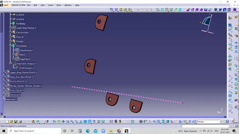
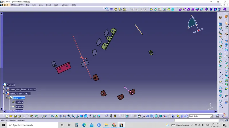
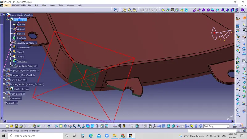
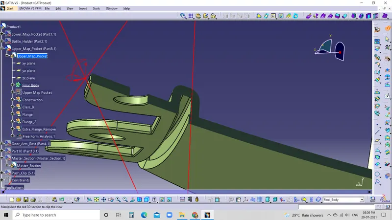
FLANGES
- A flange is a protruded ridge, lip or rim, either external or internal, that increases strength; for easy attachment/transfer of contact force with another object; or for stabilizing and guiding the movements of a machine or its parts. The term "flange" is also used as a kind of tool used to form flanges.
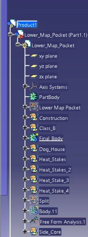
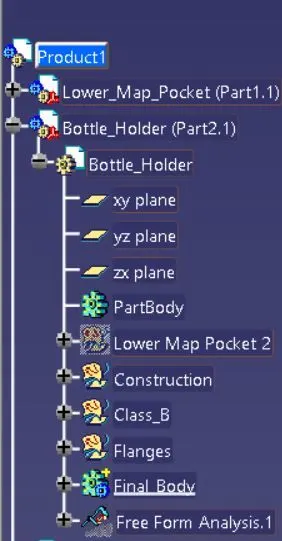
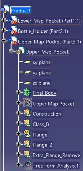
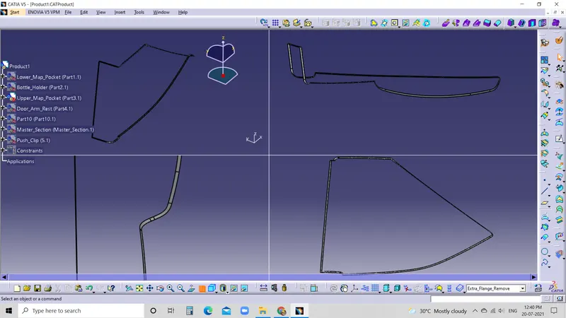
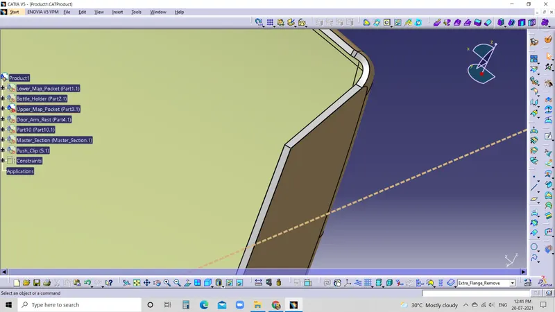
- Here we create flanges using the given master section by Extract, Line, Extrude, Trim, OffSet to 2.5MM, Closed Body and EdgeFillets (or) Extract, Line, Trim, Thickness to 2.5MM and EdgeFillets.
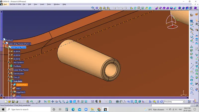
HEAT STAKES
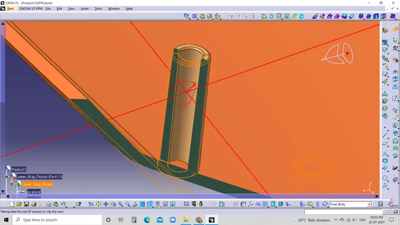
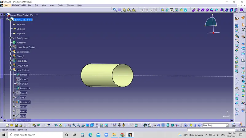
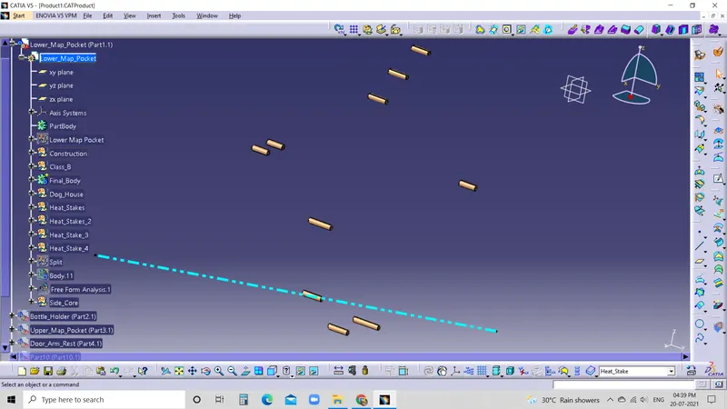
- Heat staking, also known as thermoplastic staking, is the process of joining two dissimilar materials together. In heat staking, we use local heating and cooling to raise the temperature of plastic components and allow plastic reforming to be carried out. This reforming can be used in a wide variety of applications.
What Materials Are Best Suited for Thermal Press (Heat Stakes)?
- Polycarbonate (PC)
- Polypropylene (PP)
- Polystyrene (PS)
- Acrylonitrile butadiene styrene (ABS)
- Nylons (GFN or Nylon6/6)
- Ultem (GFN or Nylon6/6) and some others.
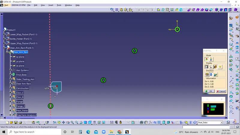
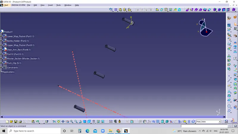
Here we create Heat Stakes using the given master section by Extract, Revolve, Thickness and EdgeFillets.
DOG HOUSE
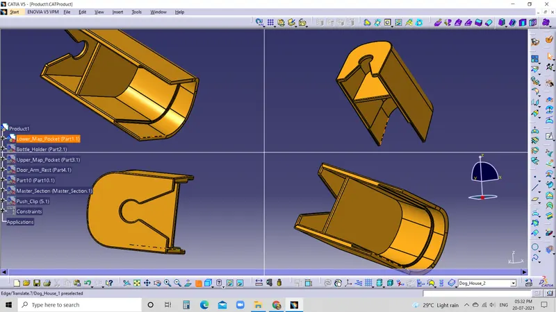
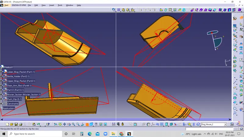
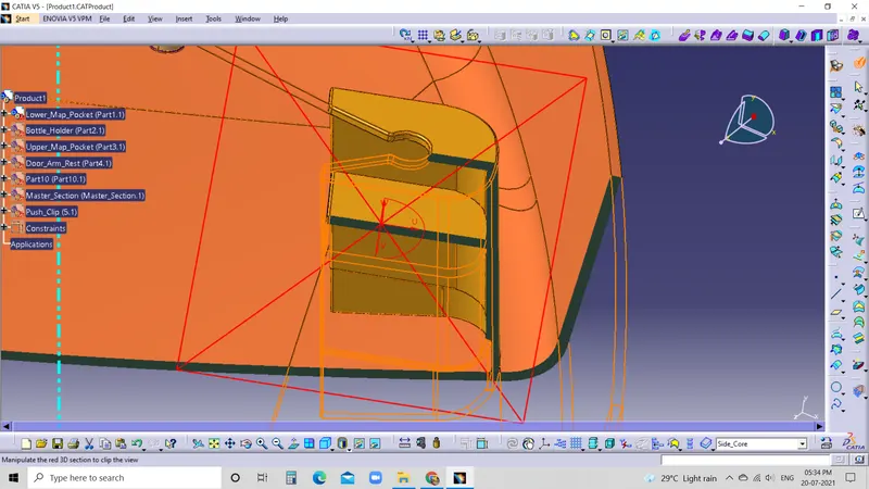
- The dog house is an engineering feature used in the plastic trim design. Dog houses are used as supporting features. Dog houses are subjected to draft analysis to prevent breakage of the component during ejection from the mould cavity. Dog house and other engineering components are built on B-surface.
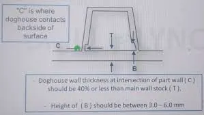
Dog house design guidelines {Used for reference}
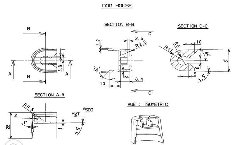
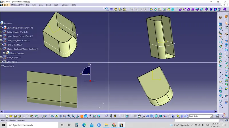
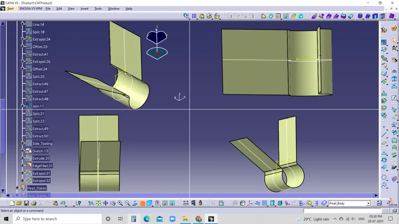
- Here we create Dog house with the given reference by Sketch, Extract, Trim, Split, Thickness, Draft to 0.5deg and EdgeFillets.
PUSH CLIPS
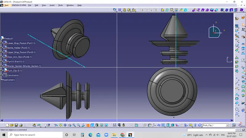
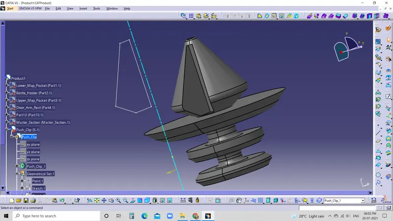
- Push clips are made from nylon 6.6. We provide push clips in black of white nylon material. It is designed to provide a fast and easy clipping application. It is a perfect fitting component for fitting multiple lightweight panels or print together.
Push clip design guidelines {Used for reference}
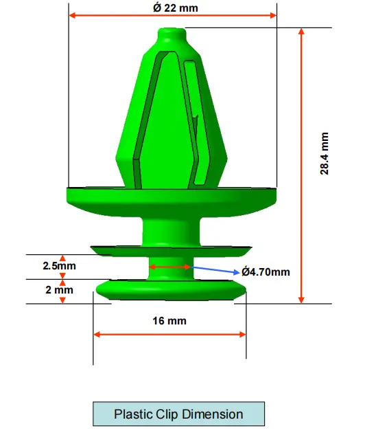
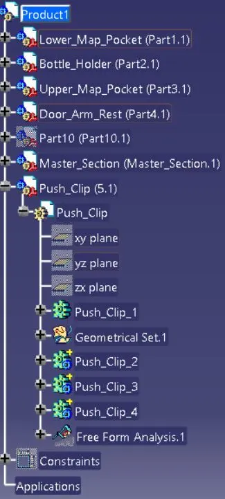
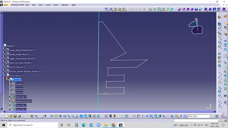
- Here we create push clips with the given reference by Sketch, Shaft, Groove, Chamfer and Edgefillets.
- Perform draft analysis for push clip with tooling axis has reference.
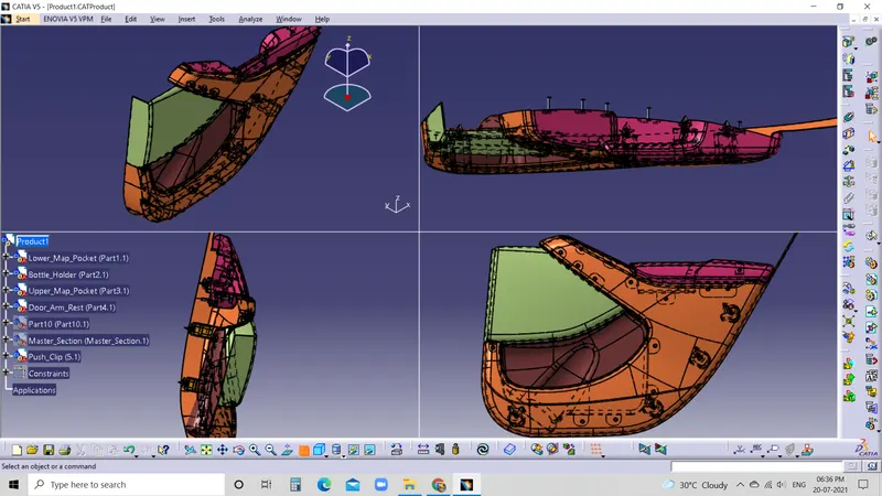
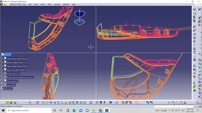
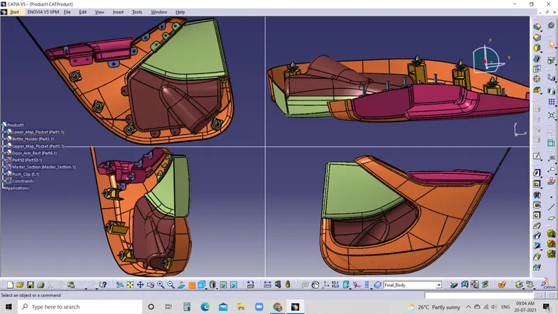
DRAFT ANALYSIS AFTER ADDITION OF B SIDE FEATURES
RESULT
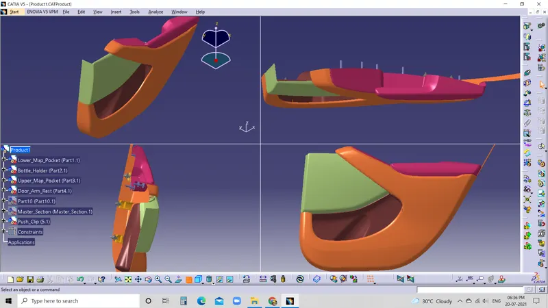
- Created thickened part using master section for reference.
- Created the mounting features as per design guidelines in the industry and with master sections(Dog House, Flanges, Heat Stakes and Push Clips).
- Performed Draft analysis.
- Created Tooling analysis.
- Checked tooling feasibility.
- Created class A, B & C surfaces.
STEPS