Week 4-1D Element Creation Challenge
AIM:
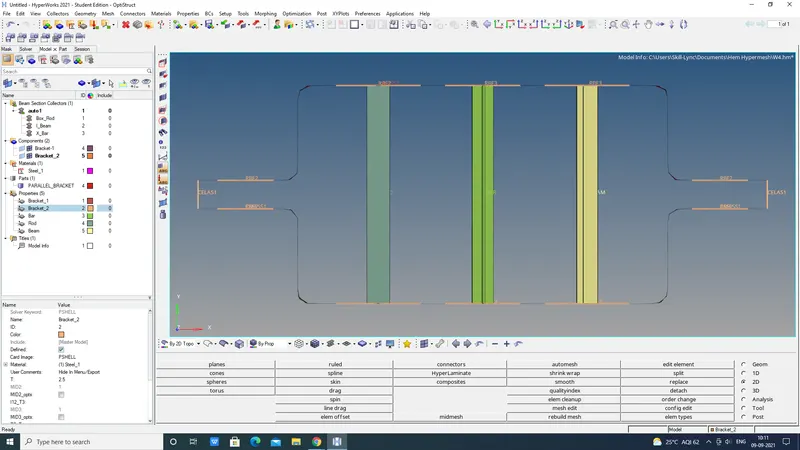
Mesh the Given component with the Size of 5 Units. Create 1D elements on the following component with given cross-section and DOF
a. Rod element:- Translational DOF should constrained with RBE2 link.
Cross-Section: BOX- Dimension a= 12 mm
Dimension b=10 mm
Thickness t= 0.75 mm
b. Beam element:- All DOF should constrained with the RBE3 link.
Cross-Section: I Section- Dimension a= 8 mm
Dimension b= 10 mm
Dimension c= 8.5 mm
Thickness t1= 0.75 mm
Thickness t2= .6 mm
Thickness t3= .6 mm
c. Bar element:- Constrain only x and y DOFs With RBE3 link.
Cross-section: X section- Dimension DIM1= 5 mm
Thickness DIM2= 1.2 mm
Dimension DIM3= 10 mm
Thickness DIM4= 1.2mm
d. & e. Apply the mass of magnitude 10 with the RBE2 link.
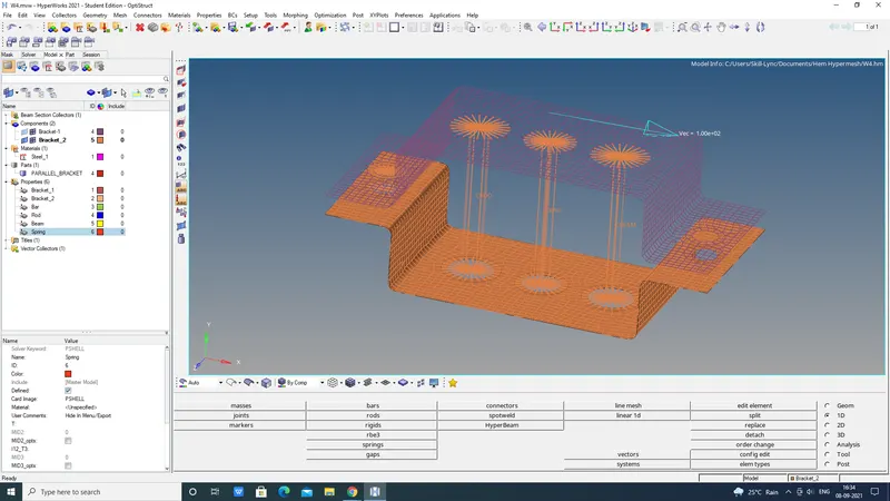
f. Join the two components with Spring elements.
:
HyperMesh is the market-leading, multi-disciplinary finite element pre-processor which manages the generation of the most significant, most complex models, starting with the import of CAD geometry to exporting a ready-to-run solver file.
HyperMesh supports various CAD and solver interfaces, making it a perfect solution for most industry verticals and domains. With its advanced geometry and meshing capabilities, HyperMesh provides an environment for rapid model generation. Generating high-quality mesh quick is just one of HyperMesh’s core competencies.
For complex sub-system generation and assembly, HyperMesh has advanced model assembly tools. Modelling of laminate composites is supported by advanced creation, editing and visualisation tools. Design changes can be made easily via mesh morphing and geometry dimensioning.
Why Hypermesh?
Preprocessing for complex Assemblies: Complete model setup of even the most complex simulations across multiple domains and industries, including automatic and semi-automatic shell, tetra, and Hexa meshing capabilities.
Open architecture Design: Robust, common FEA modelling framework with the broadest set of direct CAD and CAE interfaces, with the ability to define custom integrations.
Automated Model Build: Highly efficient for part level model building and assembly, representation, and configuration management. Intelligent connector tools and auto contact help with final model assembly.
Hyperworks is the complete package containing Hypermesh. Hypermesh is primarily a meshing software, especially for structural applications.
What is HyperWorks used for?
PROCEDURE:
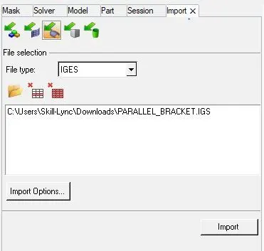
- Import the IGES model.
File> Import> Geomentry> Select IGS file> Import.
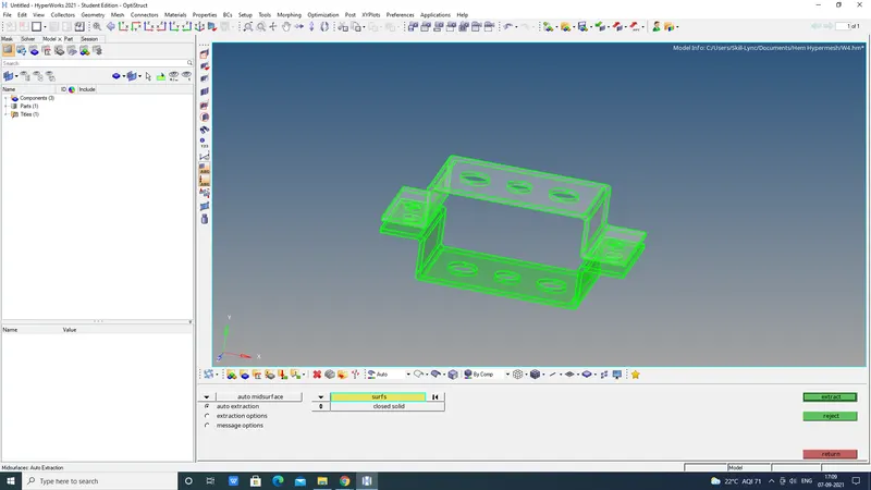
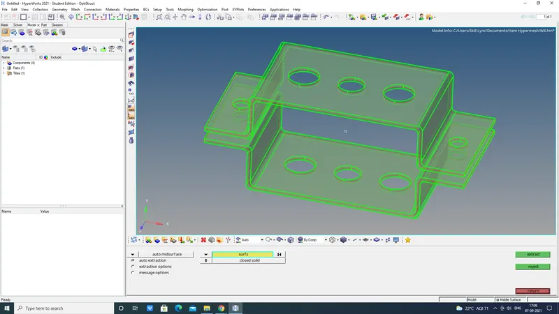
- Creation of mid surface from CAD model is given.
Geo> Midsurface> Select Bracket_1> Next> Bracket_2> Extract.
- Delete All unwanted Lines, Bodys.
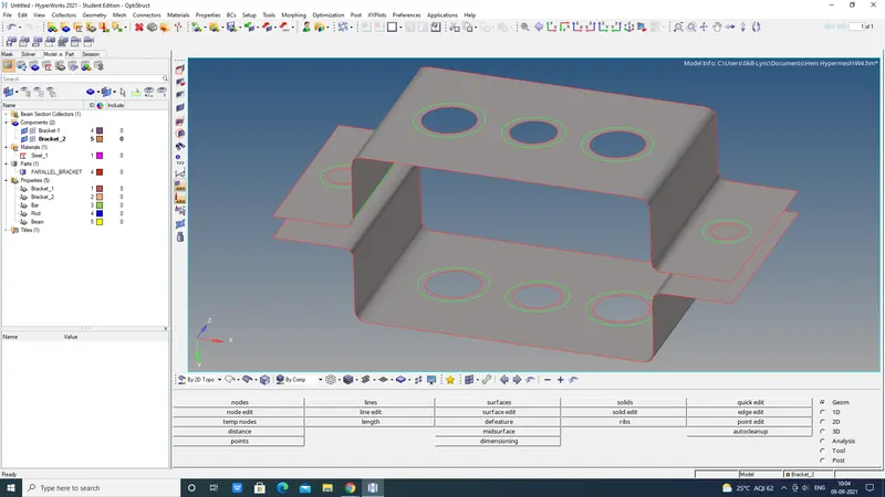
- Create the washer split with an offset value be 10units.
- Washer split is used to create a washer seated on a hole in a model. First, an offset has to be specified to determine the width of the washer and then select the line to add washers of that thickness. Elements are re-meshed based on the topology revision.
Geo> Quick edits> Washer split> Select circles> offset value 10units> return.
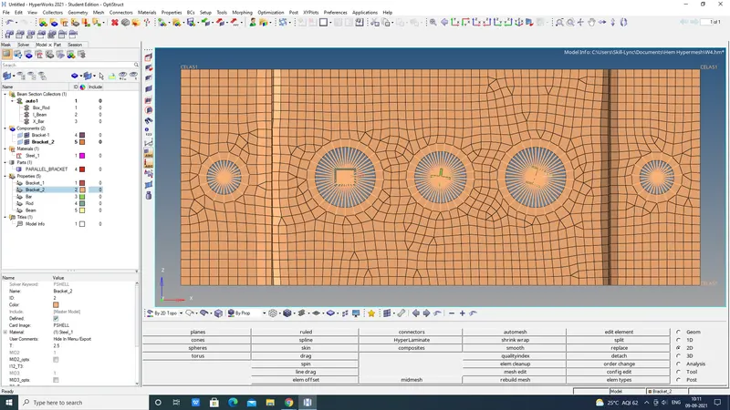
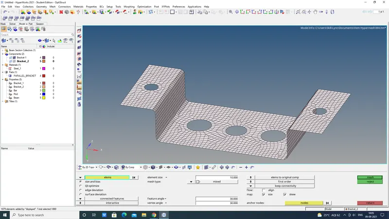
- Autoclean up, and the Auto mesh has to be done for the given brackets with an element size of 5mm.
Geo> Autoclean up> Displayed> Ok.
2D> Automesh> Mixed> Element size 10mm> Mesh.

- Creation of Material & Properties.
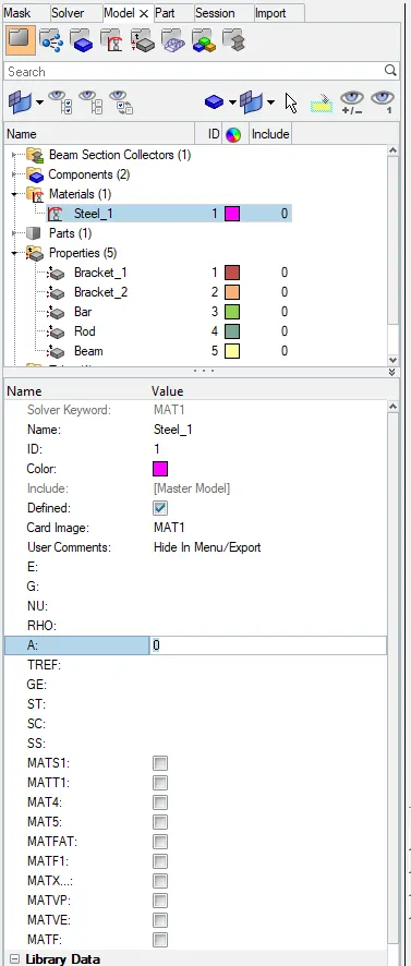
Component> Create> Material> Steel> Card image> MAT1> Ok.
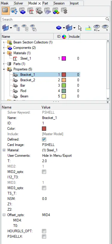
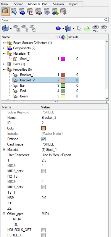
Component> Create> Property> Card image: PSHELL> Material: Steel> Thickness: 2.0> Ok.
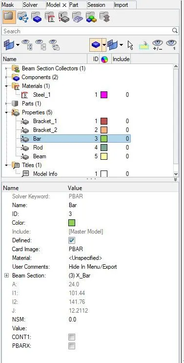
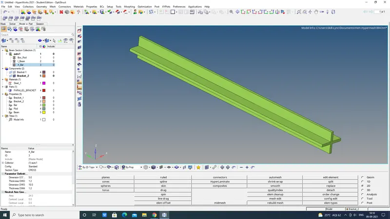
Component> Create> Property> Cardimage: PBAR> Beam section: X_Bar.
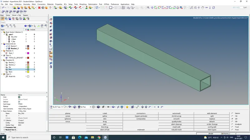
Component> Create> Property> Cardimage: PROD> Beam section: Box_Rod.
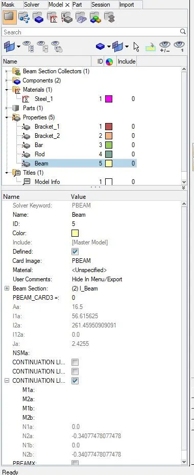
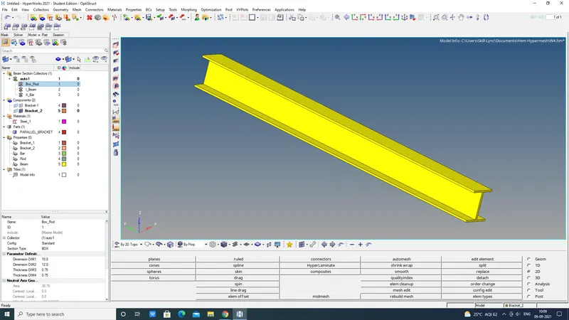
Component> Create> Property> Cardimage: PBEAM> Beam section: I_Beam.
 v
v 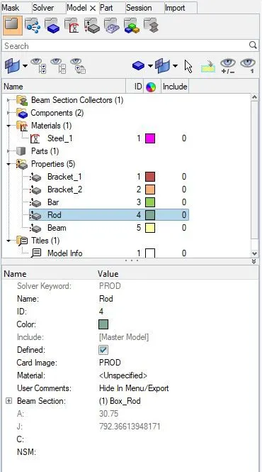
- Creation of Beam Section collectors as given dimensions and thickness.
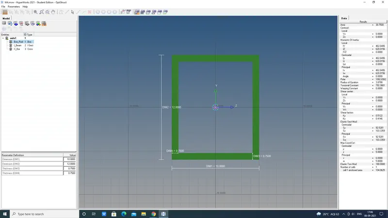
- 1D> Hyperbeam> Standard sections> Standard section library: OPTISTRUCT> Standardsection type: BOX> Create.
This command will take to Hyperbeam view BOX cross-section:
Dimension a= 12 mm, Dimension b=10 mm, Thickness t= 0.75 mm.
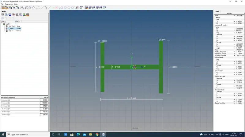
- 1D> Hyperbeam> Standard sections> Standard section library: OPTISTRUCT> Standardsection type: BEAM> Create.
This command will take to Hyperbeam view BEAM cross-section:
Dimension a= 8 mm, Dimension b= 10 mm, Dimension c= 8.5 mm, Thickness t1= 0.75 mm, Thickness t2= 0.6 mm, Thickness t3= 0.6 mm
- 1D> Hyperbeam> Standard sections> Standard section library: OPTISTRUCT> Standardsection type: BEAM> Create.
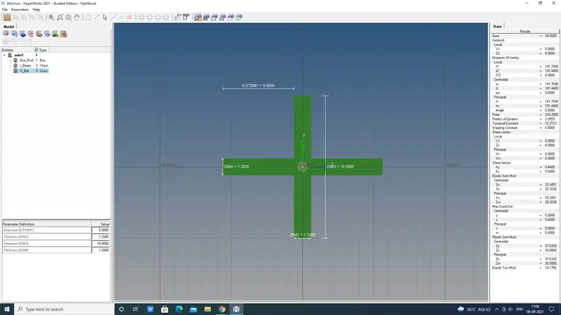
This command will take to Hyperbeam view BEAM cross-section:
Dimension DIM1= 5 mm, Thickness T2= 1.2 mm, Dimension DIM3= 10 mm, Thickness T4= 1.2mm.
- Creation of Ridge body elements 2&3,RBE2 & RBE3.
1D> Ridiges-2> Calculate node> Mulitpule nodes> By path> Select nodes> Create.

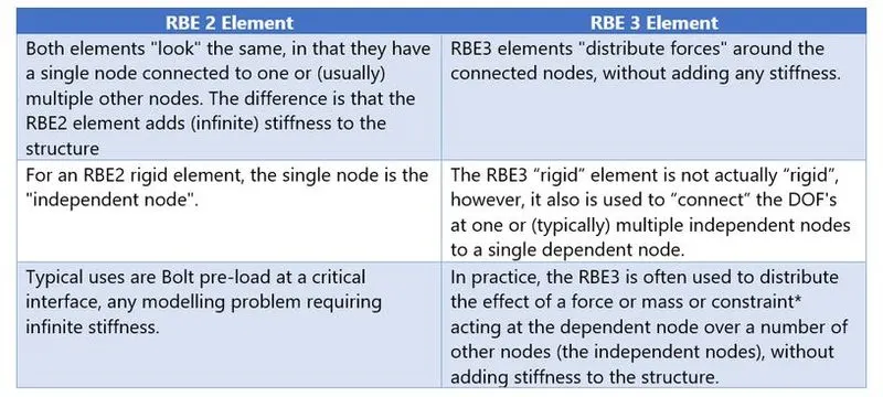
1D> RBE-3> For Beam & Bar cross-sections> Calculate node> By path> Select nodes> Create.

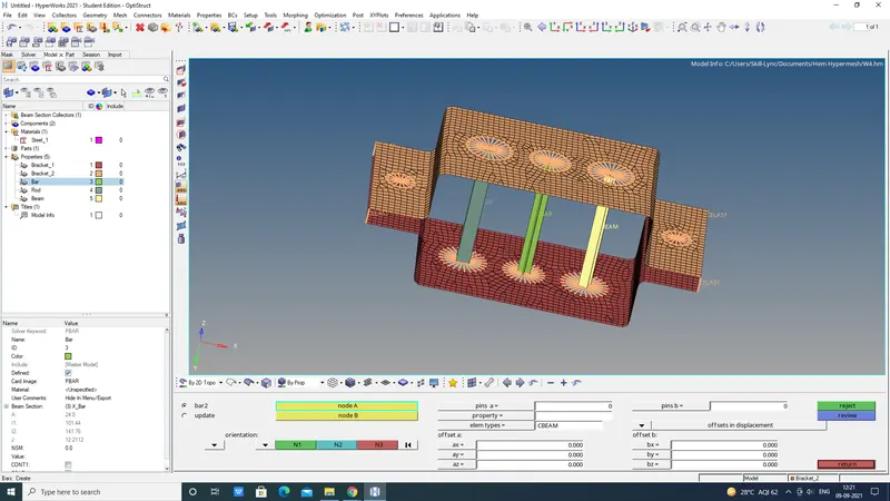
- Creation of 1D Bar, Rod & Beam and updating to there property.

1D> Bar/ Beam> Select node-A&B> Orientation> Element type: CBAR/ CBEAM> Ok.
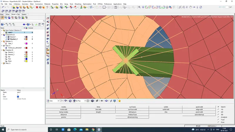
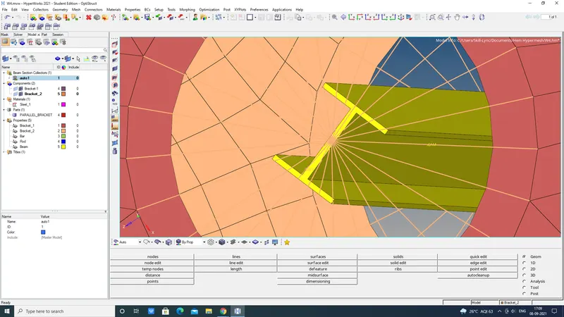
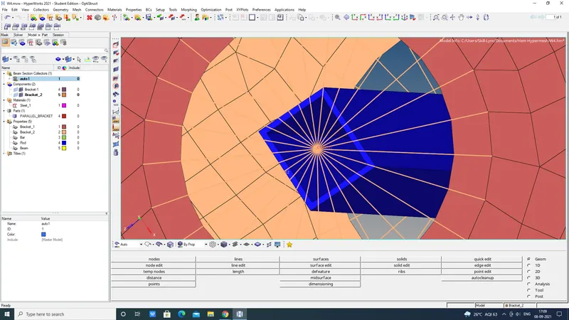
1D> Rod> Select node-A&B> Element type: CROD> Ok
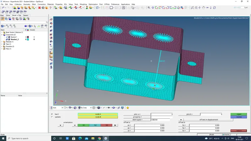
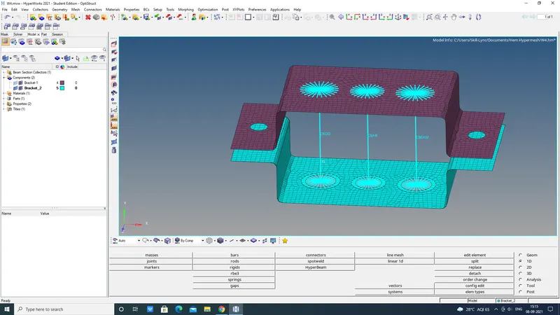
1D> Property: x_BAR/ I_BEAM/ X_ROD> Element: 1D Bar/ Beam/ Rod> Upadate.
- Apply Mass on the bracket with 10mm.

1D> Select node on RBE2 Link> Mass: 10mm> Element type: CMASS1> Create.
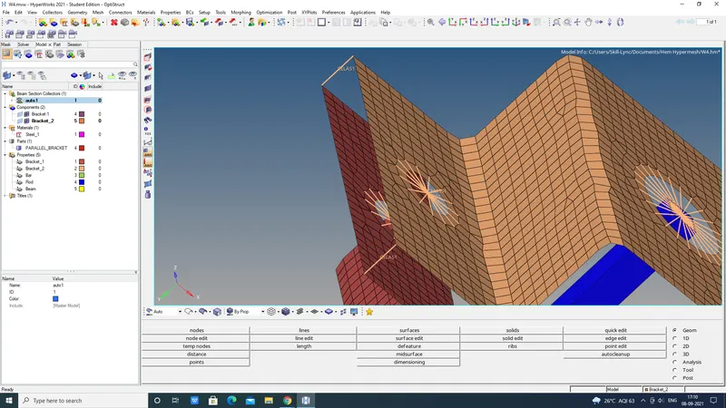
F Join 2 components with Spring elements.
1D> Spring> Select nodes> Create.
CONCLUSION:
- Extracted the mid surface from given model with 2.0 Thickness.
- Generated Mesh.
- Applied RBE2 & RBE3 Link.
- Applied 1D BAR, ROD, BEAM.
- Created Spring elements for F component.