Week 12:Project 2-Meshing of Rear Wheel Holder challenge
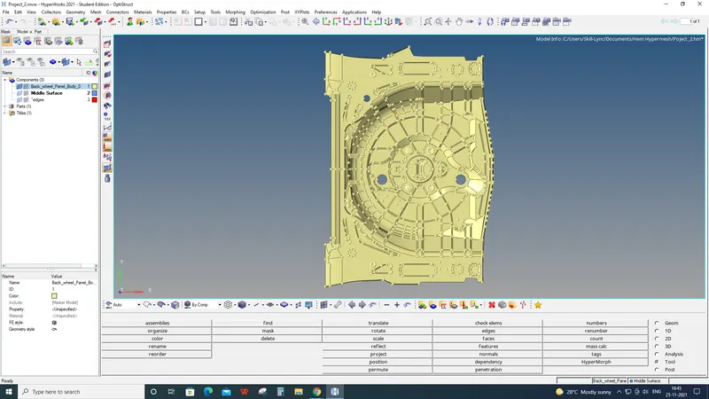
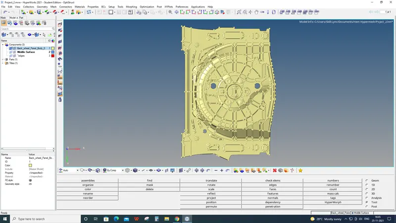
AIM: 2D Mesh of Rear Wheel Panel Body and Assigning Thickness.
ABSTRACT: The back wheel panel compartment is most often located at the trunk or rear of the vehicle. The trunk of a car is the vehicle's main storage or cargo compartment, often a hatch at the rear of the vehicle.
OBJECTIVES: Generating mid surface and 2D mesh after geometry clean up on back wheel panel body of the car and assigning thickness with following quality criteria -
Target Element Length = 5 Units
| S.N | Quality Criteria | Value |
| 1 | Aspect Ratio | 5 |
| 2 | Skewness | 45 |
| 3 | Warping | 15 |
| 4 | Taper | 0.5 |
| 5 | Min. Length | 2 Units |
| 6 | Max. Length | 8 Units |
| 7 | Min angle Quad | 45 |
| 8 | Max angle Quad | 135 |
| 9 | Min angle Tria | 20 |
| 10 | Max angle Tria | 120 |
| 10 | Tria % | 10 |
PROCEDURE:
STEP 1: Duplicate the parent surface model to another collector to keep the parent surface safe.
STEP 2: Organise the parent surface to another component collector and duplicate the surface, and move
*Tool> Organise> surface> set current component> select dest component> Duplicate> move.
STEP 3: Switch to the surface of components and remove fillets, if any which are less than the given mesh size
*Geom> defeature> surface fillet> select surface displayed> give min and max radius> find> remove
STEP 4:
Delete the unnecessary surface which is less than element size, so it will not create a bad mesh
*F2> surface> select surface> delete entity
Fill the void surface
*Geom> quick edit (F11)> filler surface> select boundary line of the circle
Toggle the line
*Geom> quick edit (F11)> Toggle edge> select boundary line of the circle
Quick Edit Panel
STEP 5: Check the thickness of the component- To get the exact thickness of the sheet, we can proceed with the following command.
Create a node to any one side of the sheet metal
*Geom> temp node> nodes> select surface> press left click to add the node> add
Project this node to the opposite side of the surface after duplicating the node.
*Tool> project > nodes> select node> duplicate> current component> to surface> Select surface> Project
STEP 6: Measuring the distance between two nodes which gives the actual thickness of the sheet.
*F4 or Geom> distance> two nodes> select both nodes by N1, N2, and we'll see the distance.
STEP 7: Repeat steps 4 and 5 to a few more surfaces to ensure the thickness of the different surfaces.
This measuring thickness will help us to know whether there is any surface that has a varying thickness and also help us to assign thickness to 2D elements after generating mesh.
In this case, there is no varying thickness so that we can generate the mid surface.
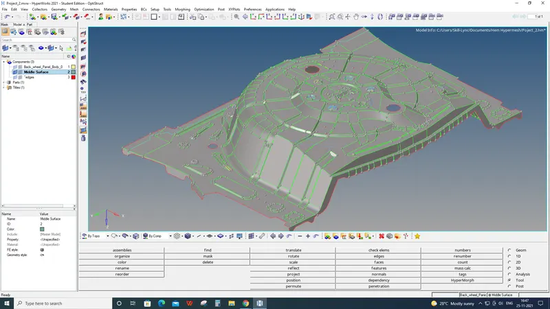
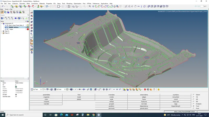
STEP 8: Creating Mid surface of the back wheel panel body.
*Geom> mid surface> auto mid surface> auto extraction> surfaces> displayed/all> extract
After creating the mid surface of that particular component, we have to proceed for geometry clean up on the mid surface to get a better mesh result by quick edit panel. We have to toggle the unnecessary lines and remove free edges. We can split surfaces which will help us mesh the surface properly and add points to create a split surface by node or line.
*Geom> quick editor (F11)
STEP 9: We can move the surface of the components to another collector so that we can work on the inner and outer sides of the back wheel panel separately.
STEP 10: We can mask the one side of the component because there are many surfaces that are symmetric, but we have to again work on asymmetric surfaces as well.
*2D> connectors> mask> surface> mask or (F5)
We can see free edges, unsuppressed lines and suppressed lines
*Toolbar> By topo
STEP 11: After cleaning up the geometry, we can proceed with 2D mesh on the surfaces one by one.
*2D> automesh> surface> select surface> set element size(5mm)> set element type(Mixed)> mesh.
STEP 12: Rotating the mesh elements.
Creating a single node at the centre.
*Geom> nodes> arc center> lines> select lines> create.
We've to rotate the mesh to 120 degrees angle two times because there are two different types of pockets, three are facing upwards, and another three are facing downwards.
*Tool> rotate> elements> select elements> z-axis> select base node(center node)> give angle(120)> rotate+ or rotate-.
STEP 13: After completing the mesh on each mid surface, check and remesh a few elements to avoid trias elements as possible to get proper mesh flow.
STEP 14: Check for the failed elements that violets gave quality parameters by setting up criteria file setting as given data.
*Menu Bar> preferences> Criteria file setting
We have to mind the given quality criteria; we can check elements by the following command-
*Toolbar> element colour mode> by element quality.
STEP 15: Correct the failed elements by Quality Index Panel and 2D remesh Panel.
STEP 16: Mesh elements should capture the given feature surface by Project panel.
*Tool> project> nodes> select nodes> to line> select lines> along vector> line normal> project
STEP 17: Reflecting meshed elements to the opposite side.
NOTE: ONLY THAT ELEMENTS CAN BE REFLECTED WHICH HAS SYMMETRIC SURFACES AND HAVE TO WORK AGAIN ON REMAINING ASYMMETRIC SURFACES.
STEP 18: Moving Mid Surface and Mesh to one collector component as we have made it separate in STEP 9.
*Tool> Organise> surface> set current component> select dest component> move.
*Tool> Organise> elements> set current component> select dest component> move.
STEP 19: Finding free edges of elements after moving elements to a single collector
Finding disconnections between elements
*Shift+F3> components> select components> give tolerance> find edges> preview equivalence> equivalence.
Connecting nodes of the elements by replace-with nodes panel. *F3
STEP 20: Assigning thickness to all the meshed elements
Measure the thickness of the parent component by following step 5.
Create a Property collector in the model tree panel.
Rename it and mention its thickness
Give the thickness manually in that particular collector details panel.
Assigning Thickness
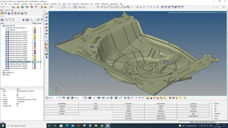
Viewing Thickness of elements
*Toolbar> element colour mode (By Property)
*Toolbar> 2D Detailed Element Representation
RESULTS:
Final Elements Quality
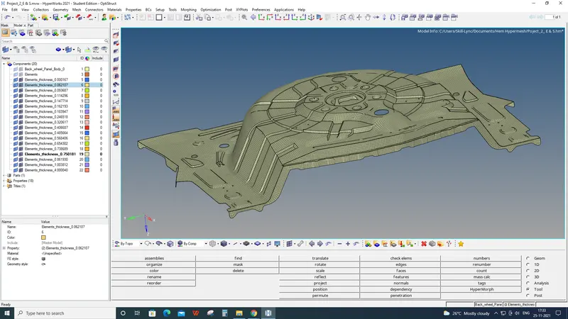
Final 2D Mesh of Rear Wheel Panel
Head Points:
Organising surfaces and elements. (Step 1, 2 and 18)
Geometry cleanup using a quick edit panel. (Step 4)
Measuring distance by projecting nodes. (Step 5 & 6)
Extracting the mid surface from the parent component. (Step 8)
Masking and unmasking surfaces and elements. (Step 10)
2D Meshing. (Step 11)
Rotating elements. (Step 12)
Setting up criteria file. (Step 14)
Fixing failed elements using quality index panel and remesh. (Step 15)
Projecting element's nodes to feature surfaces. (Step 16)
Working on an asymmetric surface. (Step 17)
Reflecting elements. (Step 17)
Finding free edges of elements and fixing them. (Step 19)
Assigning thickness. (Step 20)