Week - 4 - 2D meshing for Plastic components
AIM :
For given plastic bottle cap model, check the geometrical errors and take the mid surface. set PIDs and assign appropriate thickness to it , mesh the same for given quality criteria and enable draw shell as solid .
Note :
1.there might be some failed elements near to triple CONS or at smaller regions which are bounded by two triple CONS. Keep those OFF elements as it is if not possible to solve
GIVEN DATA:
Here given data provide are
1.Quality criteria -
Every product which has been produced will go through the set of quality check .if the quality check is fail other steps like boundary condition & applying loads will not be feasible ,
The criteria provided is mention below in the table
|
S. NO |
Quality Criteria |
Value |
|
1 |
Target / Average length |
1 |
|
2 |
Minimum Length |
0.5 |
|
3 |
Maximum Length |
3 |
|
4 |
Aspect |
3 |
|
5 |
Warpage |
15 |
|
6 |
Skewness |
45 |
|
7 |
Jacobian |
0.7 |
|
8 |
Min Quad Angle |
45 |
|
9 |
Max Quad Angle |
135 |
|
10 |
Min Tria Angle |
30 |
|
11 |
Max Tria Angle |
120 |
|
12 |
Tria % |
15 |
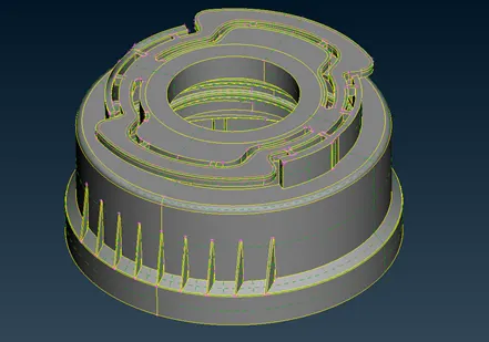
2.CAD Model -
the provided CAD is a plastic bottle cap model
Steps involve
- To check all the geometry error and rectify them
- To check the thickness of all the components in the model
- Set PIDs to varying thickness component
- To extract the mid surface from the geometry
- To generate mesh with good flow in the given quality criteria
- Assign thickness to mesh
- And enable DRAW SHELL AS SOLID
PROCEDURE:
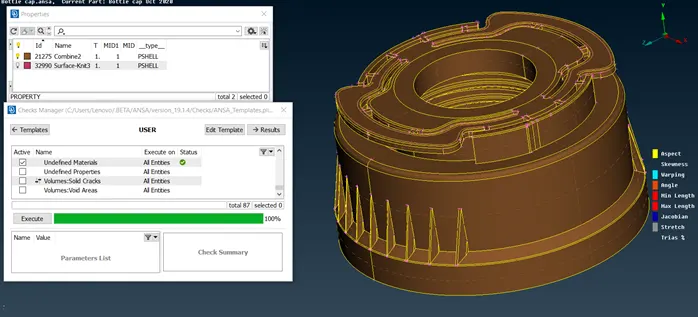
1. Check For Undefined Material
Before doing anything we have to give topo to imported CAD geometry that’s how all the red cones/single cones of imported geometry converts to double cone as double cone describes association of two adjacent surfaces and thus geometry aligns with its shared surfaces
After that we have to check how many property ID’s does parent geometry have and whether the material property is been assign to the respective PIDs or not
< PROPERTIES > Here we can observe how many property ID's are present
< MATERIALS > Here we can observe how many material properties are available and are they defined or not. if not we have to ONN the mark sign to defined or undefined it.
Then check for undefined materials in checks manager
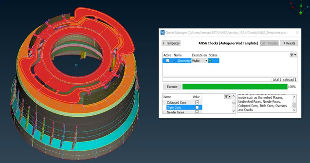
2. Check The Geometry
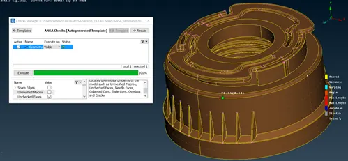
Here we have to check geometry issue with CAD before going to mesh it. it is an important stage.
For that << CHECKS MANAGERàGEOMETRY >>
Here we didn’t get any geometry issue with parent geometry but if we get any then we have to clear them by manual or automatic means
Manual can be done with the basic tool like release from cones, delete /insert from hot point, and topo
Automatic or auto fix can be done by R-click to the issue and then select fix, it will fix that issue
First try auto-fixing is some issues are not get resolve the we have to move toward manual method
3. Check the thickness
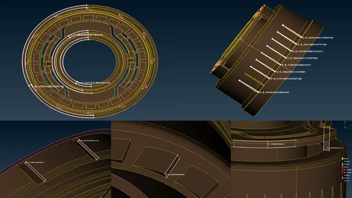
check the thickness of each varying surface in order to assign it in properties. As the given model is plastic part it will have varying dimensions and we have to measure each varying dimensions
picture below show component with some of its measurement
4. MIDSURFACING
- Mid is the neutral phase which is been generated from the cad geometry.
- The conversion of 3D to 2D CAD is happening in the mid surface generation.
- Mid surface is generated to reduce the complexity as by simplifying the cad model we get more accurate simulation results in shorter time
There are two methods by which mid surfaces can be extracted 1. auto mid, 2. manual method
for this assignment we are only going to use manual mid surfacing.
In manual mid we can use multiple methods to extract mid surfaces
As in this case we use offset
And for varying surfaces such as ribs we use Face>Middle > Single / Multi depending on situation
And if convenient use curve to form a mid-surface
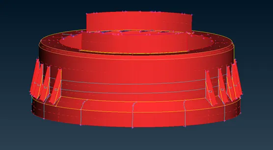
In this model there are some repeated feature such as fins and tooth. as they have same dimensions we don’t have to generate mid for each feature. we can make one and generate multiples of it having a particular pattern
Let’s see how it can be done
Firstly. generate mid for single fin
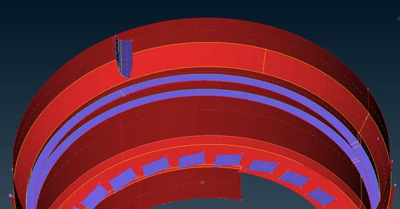
After that we have to generate two centre points by POINTSà ON COG which will help them to guide their position
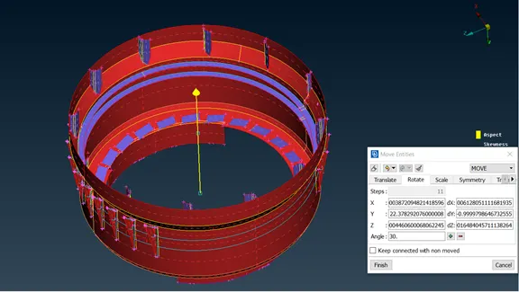
Then go to TRANSFORM > COPY > SELECT ENTITY > GO TO ROTATE
Enter steps = no. of copies we want -existing copy
Click on X: (then click on first point ) , now click on dx: (select second point )
And enter the angle =total circle angle / no. of steps
And give middle click to confirm and finally click on finish.
And we will get these repeated patterns as shown in the below picture
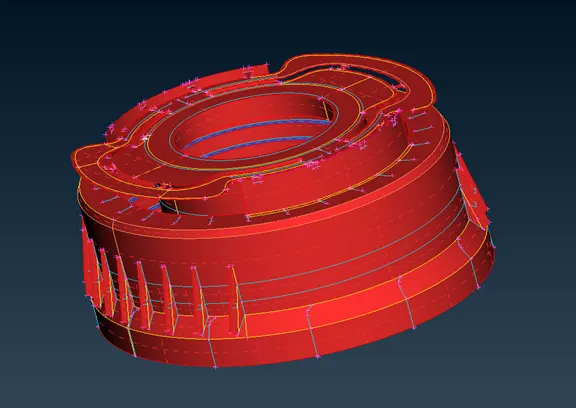
Remaining mid have to have extracted. the final mid will look something like the picture below.
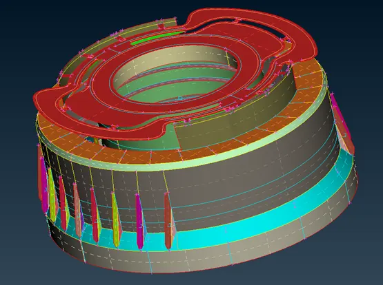
5. Set New PID'S To MID'S
For manual mid generation PID has to assign manually. For auto mid generation PID and thickness will be assigned automatically
PIDs should be set to each different thickness feature.
6. Checking Mid Surface Geometry
Check the geometry again for mid surface
7. Sizing Perimeter, De-featuring & Mesh Preparations
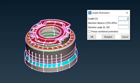
- Change all perimeter element distance to 1 mm
- Confirm whether perimeter element distances are in acceptable range
After that check whether there are any regions where element might fail. in this case ribs has little space left to cover lower filet. In order to get proper mesh flow and avoid element we extend these ribs over entire height of the filet.
Above explanation is depicted in the picture below.
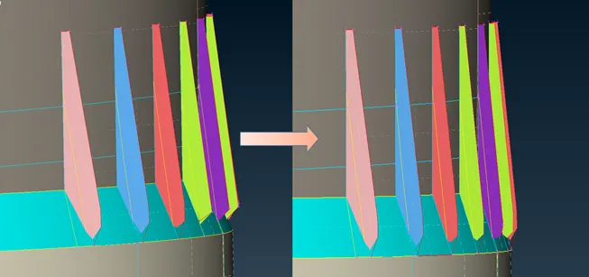
Similarly fins have little space left of around 0.116 mm which may fail for minimum length so we have to avoid this.
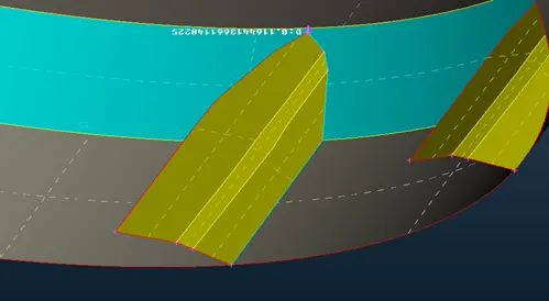
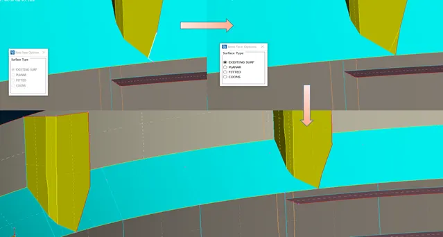
To do this we have to insert a point on fins edge and a cut from fin edge to filet corner so that we can select two lines to create a new surface using FACE > NEW > EXISTING SURF after when surface has been created join the cut
To understand this. see below picture
8. Defining Quality Criteria & Meshing Parameters
Every product which has been produced will go through the set of quality check. if the quality check is fail other steps like boundary condition & applying loads will not be feasible
We have to apply the quality criteria provided to us. in order to meet certain requirement from model
The applied quality for the model is shown below.
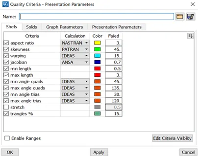
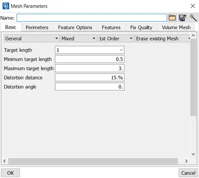
And mesh element criteria in below
9. Meshing
Definition - A mesh is a network that is formed of the cells & points. It can have almost any shape in any size & is used to solve partial differential equations each cell of the mesh represent an individual solution of equation which, when combined for the whole network result in a solution for entire mesh.
For good mesh quality divide the domain into appropriate sections by using << CUT / JOIN COMMAND >>
To apply mesh use << BEST MESH < MESH GENERATION>> and to remove the mesh use << ERASE < MESH GENERATION >>
Clear the mesh quality by the combination of
<< RECONSTRUCT/ SMOOTH < SHELL MESH >> (for automatic alternate mesh suggestions / pattern smoothing effect), << SPLIT /SWAP / JOIN > (to remove the trias and manipulate them ) ,<< MV surf < GRIDS >>(to adjust the element within surface ), << CUT /JOIN /EDGE2PERIMETER < MACROS >> (Defining the region to mesh )
Rules to be kept in mind :
. Trias should be less but should be kept where it is necessary
. Trias should always move/point towards diverging sections
. Rotational pattern should be avoided
. Uniform perimeter element number should be ensure before meshing
. Unnecessary hot points should be removed
. Feature area and fillet region should be given more care
. Element should not be fail in any quality criteria
. Trias should not moves toward more then two directions
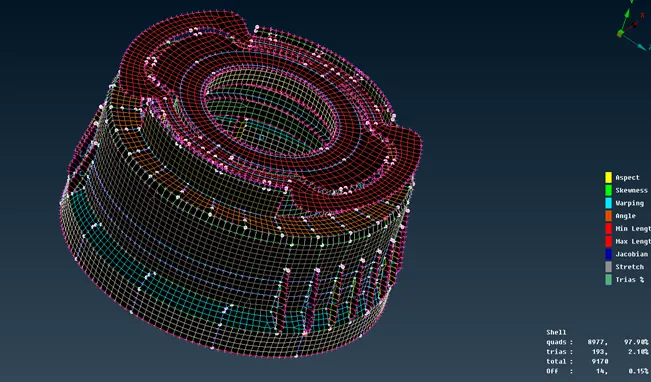
Note :
1.there might be some failed elements near to triple CONS or at smaller regions which are bounded by two triple CONS. Keep those OFF elements as it is if not possible to solve
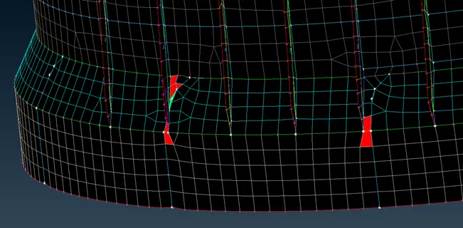
10. Assigning thickness
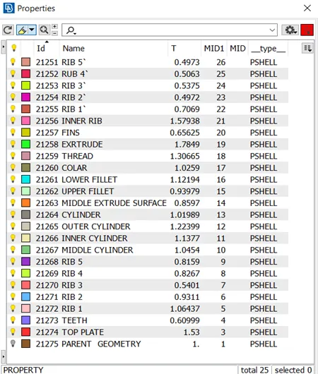
Here we have to input the thickness values in T<< T < properties manager >> which we have measured earlier for respective PID's
As it is plastic part It will have many varying features. The thickness for varying surfaces is taken by taking average of its dimensions
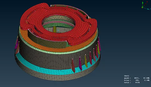
11. Enable Draw Shell As Solid
After meshing and assigning thickness enable DRAW SHELL AS SOLID from PRESENTATION PARAMETER in quality criteria. It helps us see how much our model differs and have similarity with parent geometry
Learning outcomes:
- At the end of this challenge, i can able to
- Perform geometry clean-up for any complex plastic components
- Generate mid-surface / skin for any complex plastic components.
- Generate the shell mesh meeting the given quality criteria for any complex plastic components
- Identify the quality failure and resolve the failure & improve the mesh quality
- Working with ANSA
Conclusion:
Hence mid-surfacing / meshing / and assigning thickness is done successfully for plastic bottle cap
To conclude
. Manual mid surfaces gives more accurate results
. when elements are constrain by triple cone we can’t edit the elements, we can only do reconstruction and accept the mesh given by reconstruction
. in this model in the filet region we have to prioritize mesh flow rather than element failure,as element were to be already fail anyway we can rely on mesh flow for better result approximation.