Assignment 2-RADIOSS Engine File Editing & 3D Meshing Challenge
OBJECTIVE:
1.To calculate the speed of sound through steel and the critical time step for given length
2.To edit the radios engine file with the critical time step and the frequency at which output plots are generated, for 20 steps
3.To 3D mesh the housing assembly in Hypermesh using a tetramesh with a target element size of 5mm and tet collapse of 0.15.
4.To 3D mesh the arm bracket assembly in Hypermesh using a Hex mesh and target element size of 10 mm.
1.Speed of sound through steel and critical timestep (Dt)
From the radios starter out file FIRST_RUN_0000.rad, the initial information about the material properties and the unit system followed can be determine.
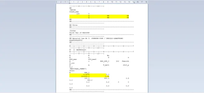
Here the material used is steel and the unit system is g-mm-ms.
The material properties in above unit system are:
Density (Rho)= 0.0078 g/mm^3
Young’s modulus (E)= 210*10^3 g /(mm.ms^2)
Poisson’s ratio=0.29.
Speed of sound can be calculated using the relation
On substitution of the above values we obtain c as 5188.74 mm/ms.
Critical timestep
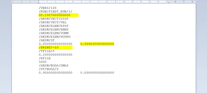
using the length of 1000 mm , the = 0.1927 ms.
The time interval at which plot should be written for 20 steps =
0.1927/20 =0.009636 ms.
2.Radioss engine out file editing
The radios file FIRST_RUN_0001.rad contains the information about the critical timestep and the time interval at which output plots are written, as shown in figure below.
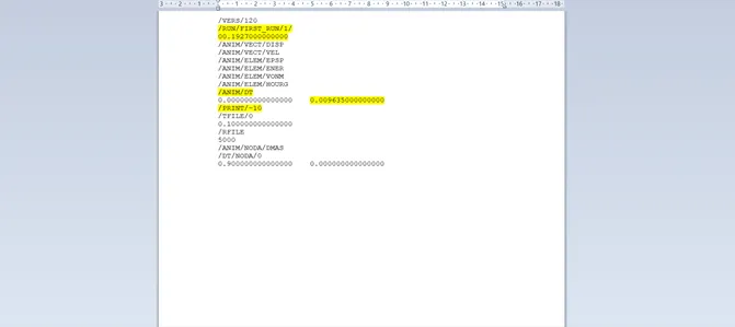
The value of timestep and the frequency are changed as shown below.
3.3D Mesh –Cover Housing – Tetramesh
The housing assembly has two components –cover and hub as can be seen in the image below.
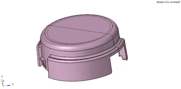
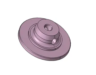
Both the components have to be meshed separately using a volume tetramesh
Cover
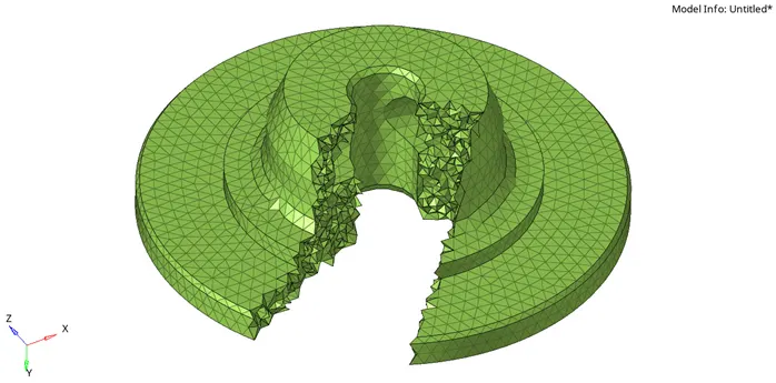
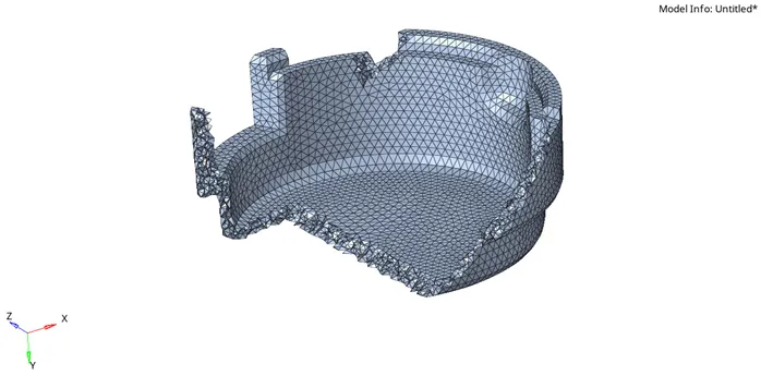
The cover is meshed using a volume tetra mesh with an element size of 5mm and tet collapse is set to 0.15.
Once meshing is been done component will appear as below.
4.Hexa Meshing of Arm Bracket
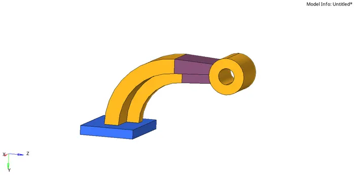
Provided arm bracket have four different regions which required to be hexa meshed accordingly, first one of it is base.
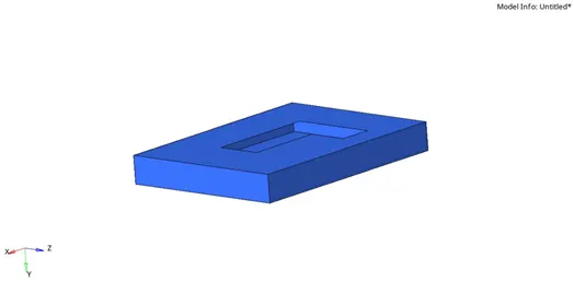
To start with it we have to isolate it from rest of the component. which can be done by using mask command available in tool sub-panel, once it is been isolated as shown above. we can move toward further processes
As we can see in above component that the base is not a close volume right now so we have to close the surface by using appropriate process. For this component we have used ruled sub panel which is available in 2D panel
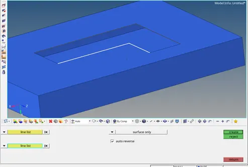
In rules command we have to select 2 sets of line between which we have to create surface and from middle drop down selector we have to select SURFACE ONLY which will allow only surface to be created
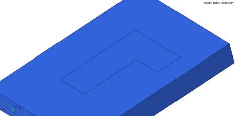
After surface has been done mesh has to be apply on the one side of surface, for which we have used automesh command available in 2D panel
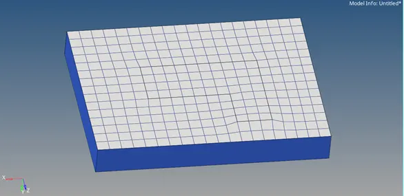
If there are trias available in mesh we have to remove them by using DRAG option available in 2D >quality index > clean up tools > drag tria element which will allow us to move the trias and remove them in opposite trias
Once mesh has been done we have to create element layers
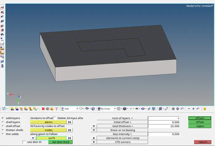
For which we have to select element which we have created earlier, for along the geometry select surface, no. of layers = 4 and total thickness 25
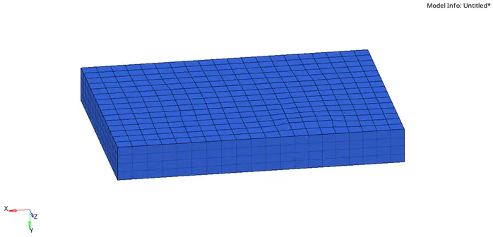
Then click on OFFSET +, once it is done the base will appear like picture shown in below
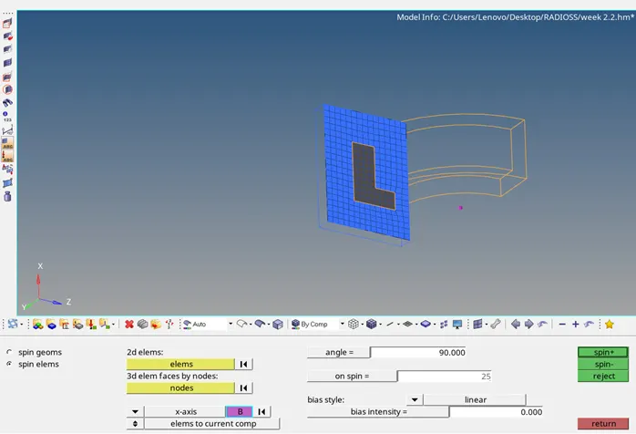
Moving forward we have to mesh curve portion for which we have to hide all hexa element in base and only keeping surface mesh elements
And use spin command in 3D to extract this mesh, in this command we need to select 2d elements from base, need a centre of curvature which can be created by three-point distance command select axis passing through centre of curvature and give the angle upto which it has to extract mesh and on spin column entre how many number of layers are required and then finally click spin -/+ to extract it
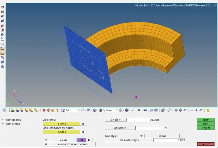
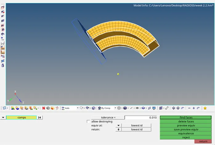
After curve portion is been meshed next portion of this bracket is straight tapper which should be meshed with Linear Solid in 3D panel for this we require face component of previously meshed curve portion this can be done with faces sub-panel available in tools panel
Select the component and click find faces it will create the face for this component
Mesh the opposite side of this portion with equal number of rows and column
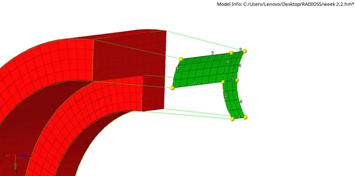
Once faces for mesh is been generated we can move to linear solid command wherein we need to select surface elements of the opposite sides of tapered component, specify position of three nodes at exact position on both side of mesh which helps mesh to get align and enter how many number of layers we require.
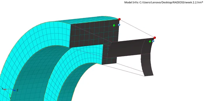
Once each input is entered click on solid which will create solid elements accordingly
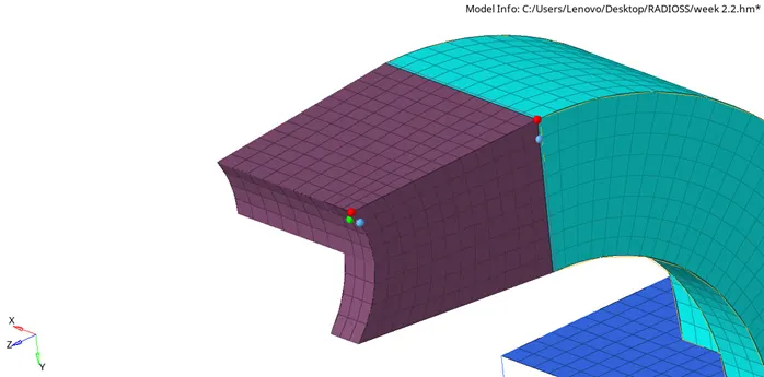
Finally moving to cylinder Bose we have to mesh one of its surface
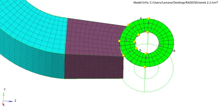
After this we will go for Solid Map in which we have to enter elements to drag ,destination surface that is opposite surface ,along the geometry should be mixed which allow us to select reference nodes and lines etc. ,and element size in along size

Once every input is selected correctly, mesh of the Bose will appear as below
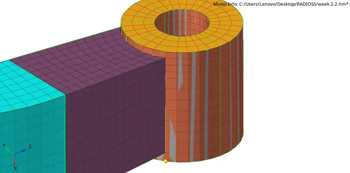
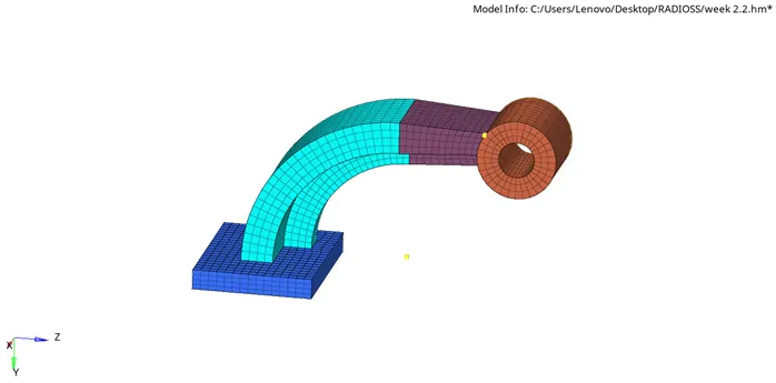
And finished meshed bracket will appear as above.
Conclusions : in hexa meshing penta element must be avoided