Project 1 - 2D meshing on the instrumental Panel
Objective:
for given component check geometrical error, extract mid with suitable method and mesh it with given quality criteria. after meshing thickness has to be assigned.
Given data:
Here given data provide are
1.Quality criteria -
Every product which has been produced will go through the set of quality check .if the quality check is fail other steps like boundary condition & applying loads will not be feasible ,
The criteria provided is mention below in the table
|
S. NO |
Quality Criteria |
Value |
|
1 |
Target / Average length |
4 |
|
2 |
Minimum Length |
2 |
|
3 |
Maximum Length |
6 |
|
4 |
Aspect |
3 |
|
5 |
Warpage |
15 |
|
6 |
Skewness |
45 |
|
7 |
Jacobian |
0.7 |
|
8 |
Min Quad Angle |
45 |
|
9 |
Max Quad Angle |
135 |
|
10 |
Min Tria Angle |
30 |
|
11 |
Max Tria Angle |
120 |
|
12 |
Tria % |
15 |
2. CAD model of an INSTRUMENT PANEL (IP):
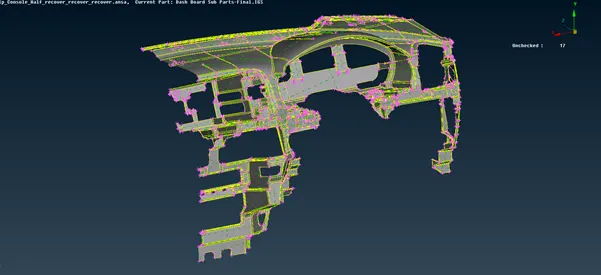
INSTRUMENT PANEL SUBSTRATE
A dashboard (instrument panel (IP)) is a control panel usually located directly ahead of vehicle’s driver, displaying instrumentation and controls for the vehicles operation. these days car dashboards may include so many indicators like speed meter, tachometer, odometer, fuel gauge,turn indicator ,gearshift position indicator ,seat belt warning light , engine malfunction light . other features may include a gauge for alternator voltage indicator, indicator of low fuel, low oil pressure, low tire pressure and fault in airbags (SRS) systems,light controls ,safety systems , entertainment equipment ,navigation system.
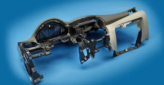
Fig. IP OF 2013 NISSAN SENTRA
The substrate may be formed from a rigid material such as metal or rigid plastic . the instrument panel doesn’t necessarily need to have heavy weight material to keep part intact , rather it can be done using the part that is lighter , save costs. But we need to make sure that the material is rigid and design good enough so that material does not fail in NVH test.
Procedure :
Topo : import the given geometry model in ANSA and do topo ( i.e the geometry model which we get might or might not having its surfaces stiched together after importing the model .) topo will stich its all surfaces according to geometry
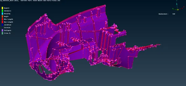
Figure 1.Geometry before topo
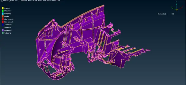
Figure 2 geometry after topo
Geometry check :
after topo has been done next step is to ensure the that geometry we get is of good quality before proceeding further .this can be done by using checks manager to check weigther any geometrical/topological errors are present in the geometry or not.
On checking the model we have got multiple errors. As shown in figure 3. We can use fix opt. available on right click and can use manual method.
For this model we have to use both
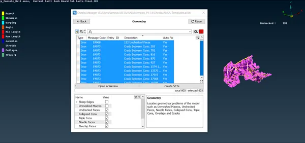
Figure 3. geometrical errors
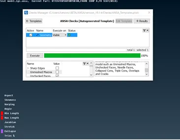
Figure 4. sucessfull check
Measurement :
each feature in the plastic model there will be an definite thickness which may be uniform or varing depending on the feature , we have to measure each feature having thickness.
measuring thickness before help in quick midsurfacing of features and to be assign in PROPERTY ID
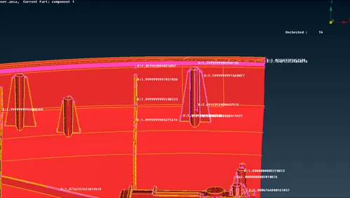
Figure 5 measurement of features
Mid surface extraction : there are three methodes by which midsurfaces can be extracted (1) manual offset method (2) skin method (3)casting method.
In manual method we have to measure thickness of the feature and offset one of its outer surface in middle .it can give us precise mid surface then other two methods but it is time consuming and it does not require geometry clean up
Skin method can give better result and it do not requires measuring thickness of the feature and automatically assign thickness and PID for it and take much lesser time than manual method but it requires close volume and geomety should be cleare,thus it takes less time than manual method but due to geometry clean up it might takes more time than casting method
Casting method is more advance method then upper two methods it can take out mid assign PID and thickness to it without measuring the feature and can do mesh with average mesh length with lesser time than above two mentioned methods but the mesh and the mid quality is not that good for this method
For this model we have used manual mathod, as geometry is complex one if we us skin or casting method here they might give some distorted feature, manual methode allows us to take out accurate mid surface .
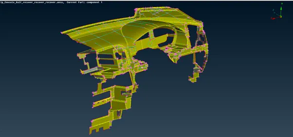
Figure 6 mid surface of IP
For outer surface of ip which is of uniform thickness we use feature command to select entire outer surface for offset in single click
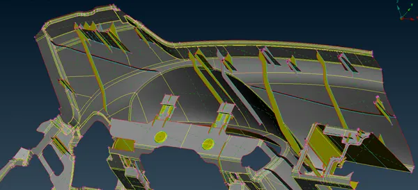
Figure 7 representation of inner features of IP
And for inner features we either use offset or middle command to extract mid surface of individual features like ribs and dog houses.
This model consist of many difficult features having complex geometry to take mid surface off. some of these feature are shown in below pictures .
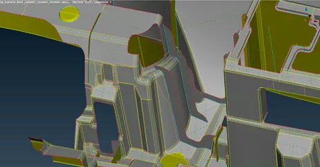
Figure 8 mid surface
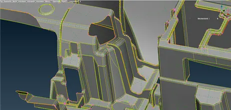
Figure 9 parent geometry
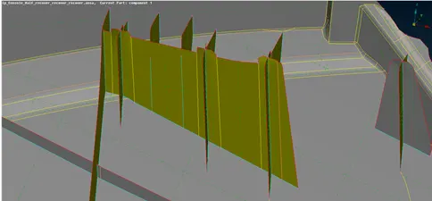
Figure 10 mid surface
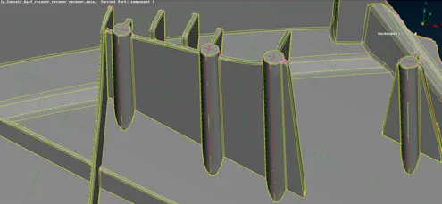
Figure 11 parent geometry
Assigning PID’s and thickness :
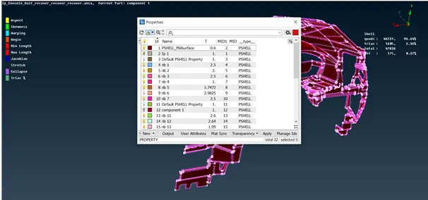
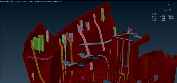
After mid surface has been extracted the next step is to assign PID’s and thickness for each varied thickness part .
as this is a plastic model it will have many varying thickness part
Mesh parameters :
before meshing we have to input mesh parameters and mesh quality criteria
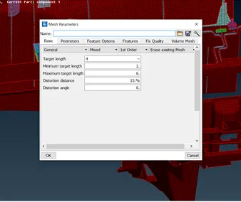
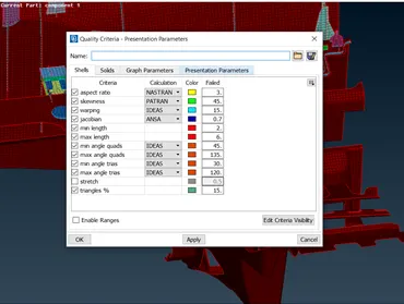
Figure 12 mesh parameter & quality criteria
Mesh generation :
Definition - A mesh is a network that is formed of the cells & points. It can have almost any shape in any size & is used to solve partial differential equations each cell of the mesh represent an individual solution of equation which, when combined for the whole network result in a solution for entire mesh.
For good mesh quality divide the domain into appropriate sections by using << CUT / JOIN COMMAND >>
To apply mesh use << BEST MESH < MESH GENERATION>> and to remove the mesh use << ERASE < MESH GENERATION >>
Clear the mesh quality by the combination of
<< RECONSTRUCT/ SMOOTH < SHELL MESH >> (for automatic alternate mesh suggestions / pattern smoothing effect), << SPLIT /SWAP / JOIN > (to remove the trias and manipulate them ) ,<< MV surf < GRIDS >>(to adjust the element within surface ), << CUT /JOIN /EDGE2PERIMETER < MACROS >> (Defining the region to mesh )
And in order to improve the meshing , we will rearrange some construction line or remove some unnecessary lines. This will be done when error cannot be eliminated without removing these lines and feature lines should not be altered too much.
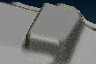
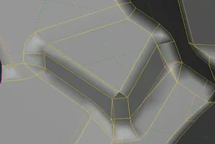
Figure 13 altered construction line
Apart from clearing qualities mesh should have uniform mesh flow ,it should not contain any opposite trias in it ,no rotating quads , and there should not be any trias near the edges . the mes we achieved is shown in below picture.
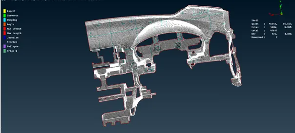
Figure 14 meshed IP
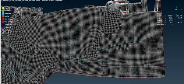
Figure 15 mesh flow
In the small areas between two triple cons and near the triple con there are some off elements present in the model as these off element cannot be removed
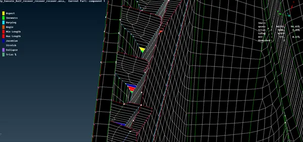
Figure 16 off element between two triple cons
For this model we have achieved
Quads : 46231, 96.64%
Trias : 1605, 3.36 %
Total : 47836
Off : 175, 0.37%
Once meshing has been done cross check assign thickness by using DRAW AS SHELL opt in prsentstion parameters
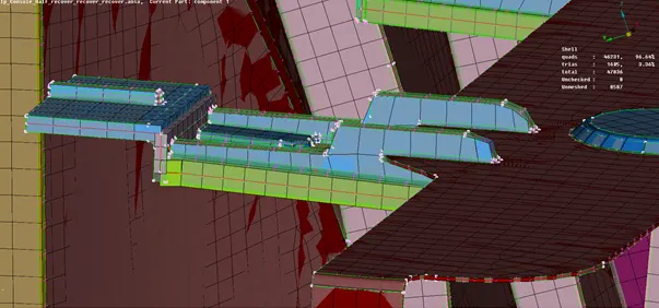
Figure 17 in draw as shell view
Learning outcomes :
- Effectively extract mid surface
- Assigning PID’s of individual parts
- Rearranging construction lines
- Meshing
- Mesh refining
- Assigning thickness to each pid
Conclusion : in complicate models. manual mid surfacing gives more accurate results and element failure between triple cons having narrow regions cannot be eliminated