Week-7 Head Impact
Aim: In this project, a children's headform model is used. we are supposed to replicate a scenario where this headform will impact on a car bonnet. The bonnet will be considered as a rigidwall for the 1st case and while using the meshed hood model a elasto-plastic material card would be used. From the simulation, the head impact coefficient will be calculated manually and with the help of Post Processing.
We will perform the Head Impact Simulation and calculate the HIC value in the Post Processing.
- We will organize a multi-include file model using the keywords *INCLUDE, *INCLUDE_TRANSFORM,*DEFINE_TRASFORMATION.
- The Impact angle of the Pedestrain Head is between 35-75 degrees.
- Create a simple elastic material model for the simple head (meshed) .
Theory: Pedestrian protection CAE is a part of vehicle safety engineering from a crash perspective. In pedestrian protection, we look for imparting minimum injury to head, upper leg (thigh), and lower leg (including knee) in case of an accident with a human subject. These tests are usually done at a lower velocity from 20-40 kmph as accidents tend to result in more severe circumstances above these velocities and braking in case of an accident often results in collision at low velocities.
DELIVERABLES
- The impact simulation of a simple head impact with the Rigid wall.
- The impact simulation of the Headform provided with the Rigid wall with the Stress / Strain plots and acceleration plot.
- The impact simulation of the headform with the Hood with the Stress / Strain plots and acceleration plot. For the hood, you can use Aluminium.
- The Stress / Strain plot from the Rigidwall simulation should be compared with the Stress / Strain plot from the Hood Simulation and there should be a detailed explanation if there is any difference in the plots.
ASSUMPTIONS & NOTES :
- In the case of Meshed_Hood. k import. We define material (Aluminium) and section thickness as per our requirement.
- The LSTC Headform is imported as it is, without any change, under the defined transformation defined in DEFINE_TRANSFORMATION.
GIVEN DATA :
A set of input files, which are to be included in the main solver file.
- Keyword file for simple head: Simple_Head_Model.k
- Keyword file for LSTC Pedestrian headform: PEDESTRIAN_HEADFORM.k
- Keyword file for automotive hood: Meshed_Hood.k
PREREQUISITES :
UNIT SYSTEM: KG / MM / MS
TIME STEP: The time step for this explicit experiment is 0.1ms to get the coarse data and time step is calculated to compensate for the flow of stress in the aluminum hood. (t = 0.0036ms)
=>>
In the case of the aluminum hood, we need to decide on what kind of simulation we need to run.
We need to study the stress propagation
We need to consider inertia effects.
We need to calculate a proper time step.
Stress propagation in aluminum.
speed of shear stress propagation, c = √(G/ρ)
where G = Shear modulus of rigidity
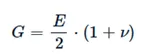
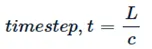
where L is element length.
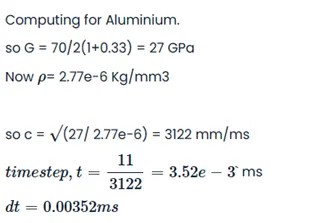
The time step should be greater than 0.00352 ms
FILE STRUCTURE: The BCs and LCs are in the main solver file, and the LSTC headform and hood are imported into the main file.
The transformations are defined *DEFINE keyword and *INCLUDE_TRANSFORMATION is used to import headform and hood under transformed conditions.
POST-PROCESSING:
Resultant acceleration and HIC(d) values are calculated for each case. Results are compared in few cases. Basically, we need to study the effects of impact on headform and quantify the effect using HIC(d).
HEAD IMPACT:
The effects of the impact on head is discussed in this report. The head impact on collision at a certain velocity and angle is studied in pedestrian head impact, results are quantified and effects are studied and tabulated. The effects are quantified using the Head Impact Coefficient (HIC)
A universal expression for HIC is given below, It is called Free Motion Headform HIC:
HIC = max(t1, t2) {[1/(t1-t2)∫∫a(t)dt]^2.5 * (t1-t2)} where integration is from t1 to t2`
There are various standards according to which Free Motion Headform HIC can be formulated as a finite value:
As per Federal Motor Vehicle Safety Standard (FMVSS) No. 201,
HIC(d) = 0.75446 * (Free Motion Headform HIC) + 166.40.
There are various levels of consequences and HIC value determine the probability of those levels prevailing:
LEVEL1: Slight damage to brain (headache, dizziness, contusion)
LEVEL2: Detached ratina, 15 mins consiousness, nose fracture, contusion with or without skull fracture.
LEVEL3: Detached ratina, 15 mins consiousness, nose fracture, contusion with or without skull fracture. Multiple skull fracture, loss of vision, multiple facial fracture, and unconsciousness without any neurological damage.
LEVEL4: Multiple skull fracture with neurological damage.
LEVEL5: More than 12 hours of unconsciousness, hemorrage in skull and critical neurological condition.
LEVEL6: Death, cervical fracture with damage to spine.
For Example:
If HIC(d) = 650
Level1: 90% probability
Level2: 55% probability
Level3: 20% probability
Level4: 5% probability
NOTE:
1. The time interval for HIC calculations is < 36ms>
2. For HIC calculation we only consider acclrn/ deacclrn peaks which last atleast 3ms because such Severity Index values only create damage to pedestrian on impact. sometimes we also consider interval <15>
CASE1: Simple head at 30kmpl with Rigid wall
KEYWORDS:
*INCLUDE
This keyword helps in importing an external file into the main solver file as:
- It helps in getting data drom read-only files.
- It helps in inter-team collaboration.
Include>>Include>>Enter path>>Insert>>Accept>>OK
Path of file:- ../../Simple_Head_Model.k
Save the Input file 2 steps down from included file.
Load Input file, and input file parameters will be available in loaded input file.
Here, no transformations are entered in included file and it is included as it is in the main solver file.
*SET
1. Set of nodes created to assign velocity to the simple head.
Create Entity>>Set Node>>Create>>select all nodes of head using area selection>>Apply
NSID = 1
*RIGIDWALL
Create Entity>>Rigidwall>>rigidwall>>Planar>>select node>>translate -15mm>>apply.
*CONTACT
As elements of head need not to penetrate each other so single surface contact need to be defined.
Automatic_single_surface.
SSID = as PID
SSTYP = 3
*INITIAL
To assign velocity to set node NSID =1
Velocity = 30kmpl = 30*1000*1000 mm/ 60*60*1000 ms = 8.333 mm/ms
velocity is in negative x direction.
*CONTROL
1. Energy - To balance the energy as hourglass energy to be included.
2. Termination - 20ms
As 15mm/(8.333 mm/ms) = 1.80 ms is the time of approach.
so impact is studied for 18.20 ms.
*MATERIAL
024_PIECEWISE_LINEAR_PLASTICITY
1. MID =4
2. DENSITY = 7.850e-6
3. YOUNGS MODULUS = 2010
4. POISONS RATIO = 0.3
5. YIELD STRESS = 0.3115
6. ETAN = 1.3
*SECTION
1. Shell elements
2. ELFORM = 2
3. SectionID = 5
*PART
1. SecID =5
2. MatID =4
3. PartID =5
*DATABASE
1. ASCII output files
- GLSTAT, DT = 0.5
- NODOUT, DT = 0.5
- RWFORC, DT = 0.5
2. BINARY.D3PLOT, DT = 0.5
3. EXTENT_BINARY, STGFLAG = 1 to compute the elstic stress and strain in the body.
4. HISTORY_NODE, for Node 69022 to compute the HIC(d) and resultant acceleration.
POST-PROCESSING:
Simulation video:
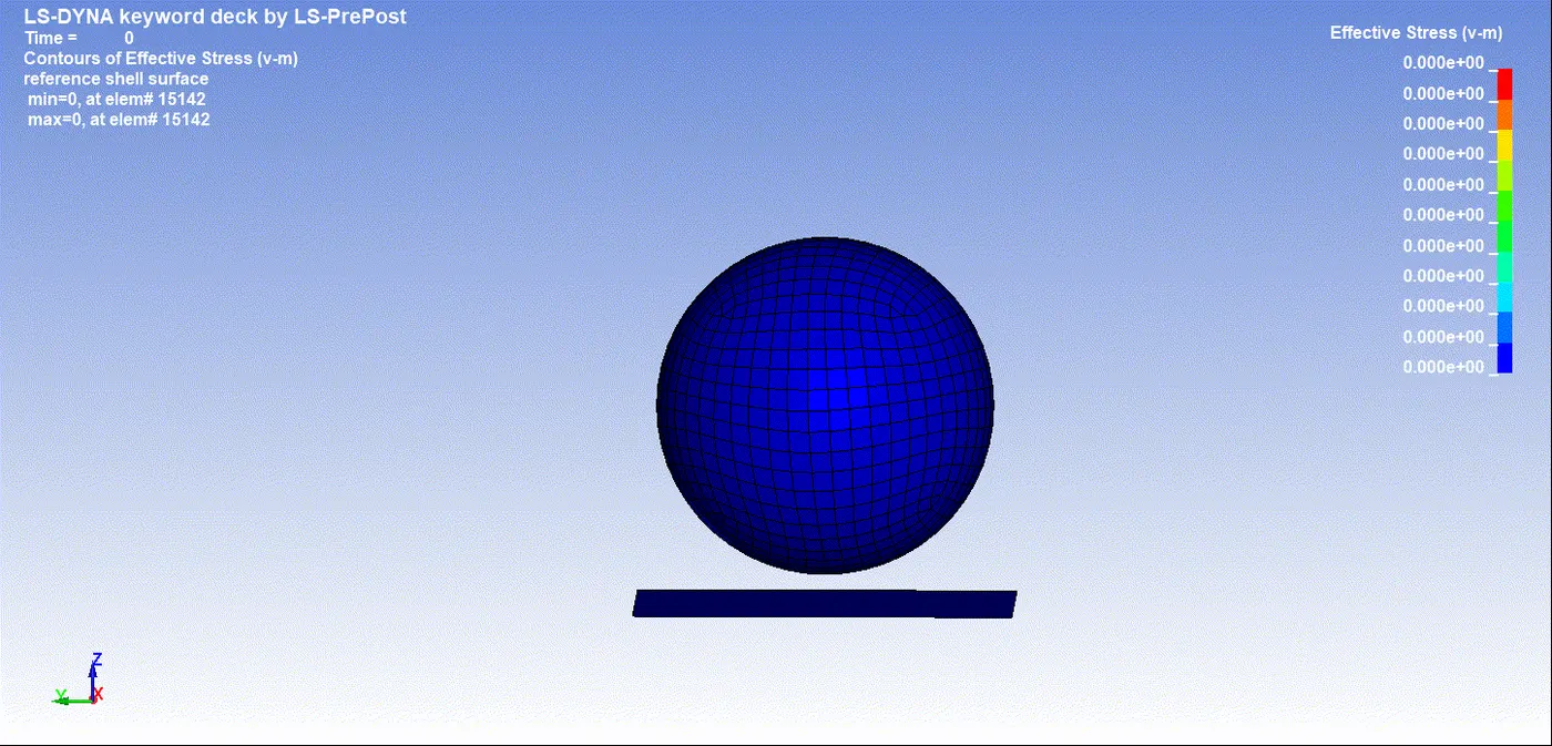
V-m Stress/ Efective plastic Strain with time. and Stress Vs Strain plots (For element #15346)
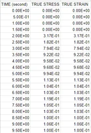
Figure <!-- [if supportFields]> SEQ Figure \* ARABIC <![endif]-->1<!-- [if supportFields]><![endif]-->_TRUE STRESS AND STRAIN AT ELEMENT # 15346
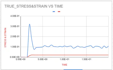
Figure <!-- [if supportFields]> SEQ Figure \* ARABIC <![endif]-->2<!-- [if supportFields]><![endif]-->_STRESS/STRAIN VS TIME#ELEMENT#15346
Energy Plot:
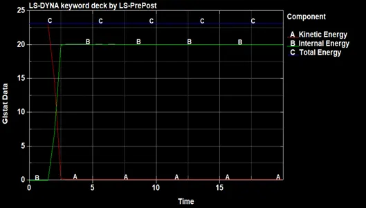
Figure <!-- [if supportFields]> SEQ Figure \* ARABIC <![endif]-->3<!-- [if supportFields]><![endif]-->_Depicts the energies
Rigidwall Forces:
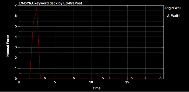
Figure 4_Rwall Forces
Acceleration Plot
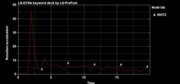
Figure 5_Resultant accellaration
CASE2: Pedestrian Headform at 30kmph, 35degrees with Rigid wall.
Keywords:
Here we will import the Child headform with a certain angle through *define_transformation & include transform. And impact it with rigid wall.
Note:
define transform only defines the position of incude in space
STEPS:
*DEFINE
Transformation 1:
*DEFINE_TRANSFORMATION
TRANID = 1
Title: Headform_y_35degrees
ROTATE: 0 1 0 0 0 0 35
Here, a line inclined at 35 degrees with Y and perpendicular to X and Z is included as transformation
The imported file will be inclined to 35 degrees with Y.
*INCLUDE
The file included is of LSTC Pedestrian headform which contains modelling for headform
LSTC.PEDESTRIAN_HEADFORM_CHILD.180605_V1.03.2BETA.k
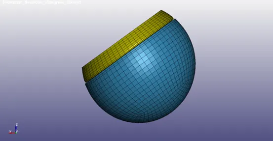
Figure <!-- [if supportFields]> SEQ Figure \* ARABIC <![endif]-->4<!-- [if supportFields]><![endif]-->_lstc headform filename-pedestrian_headform.k
*INCLUDE_TRANSFORMATION
Include transform calls out the include which is to be transformed through define transform
TranID = 1
Path: ../../../PEDESTRIAN_HEADFORM.k
As imported files is 2 steps up from the location of main solver file.
Using this file headform is imported at an angle 35 degrees with Y.
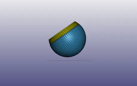
Figure 2.2 Pedestrian headform imported into main solver file under above mentioned transformations. (RIGHT SIDE VIEW).
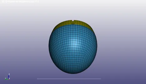
Figure 2.3_ Front view
*INITIAL
To assign velocity to headform nodes, it is very much necessary to create a set of nodes.
*SET_NODE
Title: Velocity_nodes
NSID = 3
All nodes of headform are selected by area box.
*INITIAL_VELOCITY
NSID = 3
Velocity = 30 kmph = 8.3333 mm/ms
The velocity vector is in X-Z plane.
X componenet of velocity at 35 degrees with X.
Vx = -8.333cos 35 = -6.826 mm/ms
Z componenet of velocity at 35 degrees with X.
Vz = -8.333sin 35 = -4.779 mm/ms
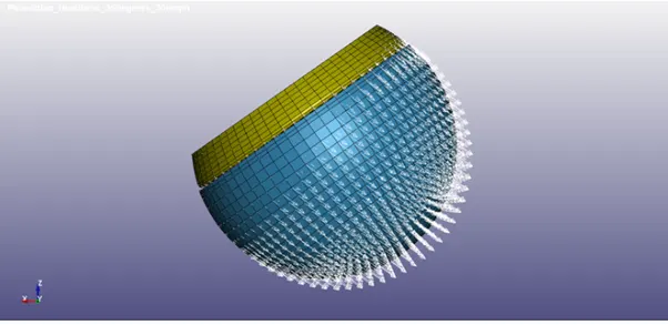
Figure <!-- [if supportFields]> SEQ Figure \* ARABIC <![endif]-->5<!-- [if supportFields]><![endif]-->_Velocity vector for headform. (Right side view)
*CONTACT
Contacts are established to avoid penetration of skull into skin.
Contacts are established to avoid penetration of skin into hood.
Self contacts are established to avoid self penetrations of componenets.
*AUTOMATIC_SURFACE_TO_SURFACE
MSTYP = 3 to define part set id.
SSTYP = 3 to define part set id.
SSID = 2 (skin)
MSID = 1 (skull)
To avoid penetration of skull into skin
*CONTROL
Termination = 40ms
The solution of problem will happen for this time period.
*DATABASE
ASCII
*GLSTAT, dt = 0.5 - To retrieve data for energies.
*NODOUT, dt = 0.5 - To retrieve data for node specified under *History_node
*BINARY.D3PLOT, dt = 0.5 - to retrieve binary file for post processing.
*EXTENT_BINARY, STRFLG = 1 - to retrieve data for stress and strain with time.
Post-Processing:
Simulation Video:
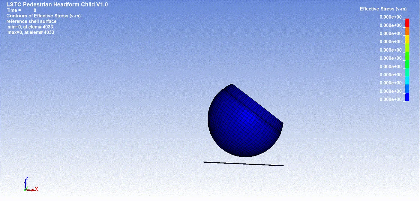
Figure 3.1_Animation of effective stresses
Resultant acceleration for Head Accelerometer. (Node 25679)
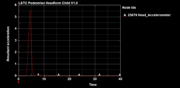
Figure 3.2_Resultant acceleration for Head Accelerometer. (Node 25679)
Head Impact Coefficient calculation:
Head_accelerometer data is calculated for peak acceleration to quantify the effect of collision.
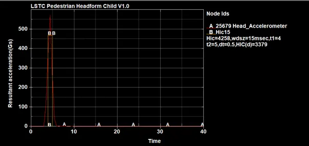
Figure 3.3 HIC15 and HIC(d) value from resultant acceleration.
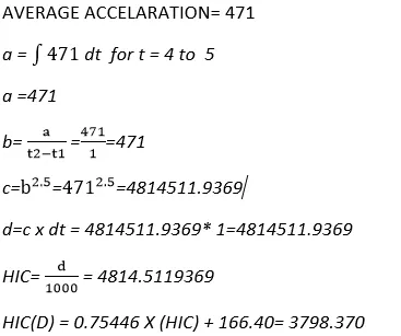
HAND CALCULATION:
|
AGV. ACCELERATION |
TIME PARAMETERS |
Ls PrePost calculation |
Hand calculation |
||||
|
t1 |
t2 |
t3 |
HIC |
HIC (D) |
HIC |
HIC (D) |
|
|
471 |
4 |
5 |
1 |
4258 |
3379 |
4814 |
3798.370 |
CASE 3: Pedestrian Headform at 30kmph and 35degrees with Meshed hood.
PROCEDURE:
The included files are for Hood and LSTC Hadform.
The main solver file contains the boundary conditions and the Load conditions.
The main solver file also contains the output files and termination and time step.
*KEYWORDS
*DEFINE
Transformation 1:
*DEFINE_TRANSFORMATION
TRANID = 1
Title - Hood
SCALE - 0 0 0 0 0 0 0
It is a dummy transformation, and it will import the included file as it is.
Transformation 2:
*DEFINE_TRANSFORMATION
TRANID = 2
Title: Headform_y_35degrees
ROTATE: 0 1 0 0 0 0 35
Here, a line inclined at 35 degrees with Y and perpendicular to X and Z is included as transformation
The imported file will be inclined to 35 degrees with Y.
*INCLUDE
The file included is of LSTC Pedestrian headform which contains modelling for headform
LSTC.PEDESTRIAN_HEADFORM_CHILD.180605_V1.03.2BETA.k
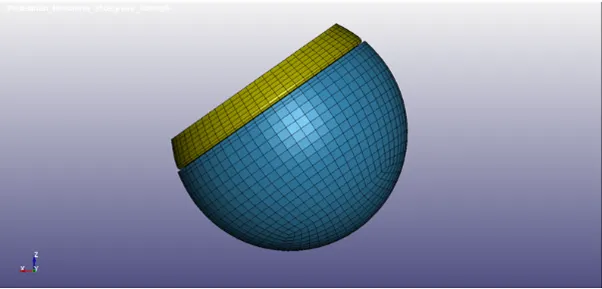
Figure 4.1_LSTC Headform. Filename - PEDESTRIAN_HEADFORM.k
The file included is a meshed hood which comprised of quad-tria shell elements.
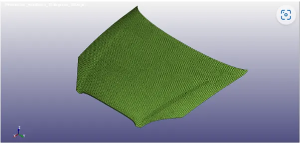
Figure <!-- [if supportFields]> SEQ Figure \* ARABIC <![endif]-->4.2<!-- [if supportFields]><![endif]-->_Meshed hood. File name- Meshed_Hood.k
*INCLUDE_TRANSFORMATION
TranID = 1
Path: ../../../Meshed_Hood.k
As The imported file is 2 steps up from the location of the main solver file.
Using this file hood is imported as it is into the main solver file.
TranID = 2
Path: ../../../PEDESTRIAN_HEADFORM.k
As imported files is 2 steps up from the location of main solver file.
Using this file headform is imported at an angle 35 degrees with Y.
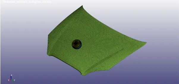
Figure 4.3_Meshed hood and headform imported into main solver file under above mentioned transformations. (ISO-METRIC VIEW)
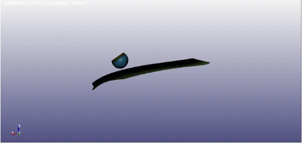
Figure <!-- [if supportFields]> SEQ Figure \* ARABIC <![endif]-->4.4<!-- [if supportFields]><![endif]-->_Meshed hood and headform imported into main solver file under above mentioned transformations. (RIGHT SIDE VIEW)
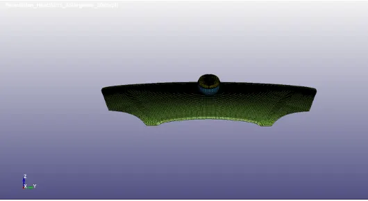
Figure <!-- [if supportFields]> SEQ Figure \* ARABIC <![endif]-->4.5<!-- [if supportFields]><![endif]-->_Meshed hood and headform imported into main solver file under above mentioned transformations. (FRONT VIEW)
*INITIAL
To assign velocity to headform nodes, it is very much necessary to create a set of nodes.
*SET_NODE
Title: Velocity_nodes
NSID = 3
All nodes of headform are selected by area box.
*INITIAL_VELOCITY
NSID = 3
Velocity = 30 kmph = 8.3333 mm/ms
The velocity vector is in X-Z plane.
X componenet of velocity at 35 degrees with X.
Vx = -8.333cos 35 = -6.826 mm/ms
Z componenet of velocity at 35 degrees with X.
Vz = -8.333sin 35 = -4.779 mm/ms
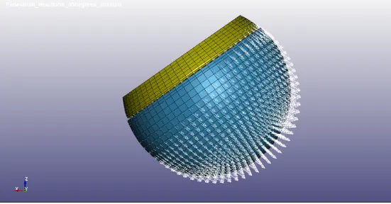
Figure <!-- [if supportFields]> SEQ Figure \* ARABIC <![endif]-->4.6<!-- [if supportFields]><![endif]-->_Velocity vector for headform. (Right side view)
*CONTACT
Contacts are established to avoid penetration of skull into skin.
Contacts are established to avoid penetration of skin into hood.
Self contacts are established to avoid self penetrations of componenets.
*AUTOMATIC_SURFACE_TO_SURFACE
MSTYP = 3 to define part set id.
SSTYP = 3 to define part set id.
SSID = 2 (skin)
MSID = 1 (skull)
To avoid penetration of skull into skin
MSTYP = 3
SSTYP = 3
SSID = 2 (Skin)
MSID = 2000300 (Hood)
To avoid penetration of skin into hood.
*AUTOMATIC_SINGLE_SURFACE
SSTYP = 3
SSID = 1,2,3,4,5,2000300
To avoid self penetration or buckling and to study plastic strain and fracture.
*CONTROL
Termination = 50ms
The solution of problem will happen for this time period.
*DATABASE
ASCII
*GLSTAT, dt = 0.5 - To retrieve data for energies.
*NODOUT, dt = 0.5 - To retrieve data for node specified under *History_node
*BINARY.D3PLOT, dt = 0.5 - to retrieve binary file for post processing.
*EXTENT_BINARY, STRFLG = 1 - to retrieve data for stress and strain with time.
*MATERIAL
Material for Hood is to be determined.
Material Card - Piecewise linear plasticity *MAT_024
Material - Aluminium
Density - 2.77e-3 kg/mm3
Modulus of Elasticity - 70 GPa
Yield Stress - 0.115 GPa
Tangent Modulus - 1.082 GPa
*SECTION
A section for shell elements is defined with following properties:
ELFORM - 2
Thickness - 1.5mm
Post-Processing:
Simulation
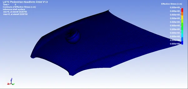
Figure 4.7_animation of headfoam in hood impact
Element under analysis:
Element#3697#3025#3029#3361 are element under analysis.
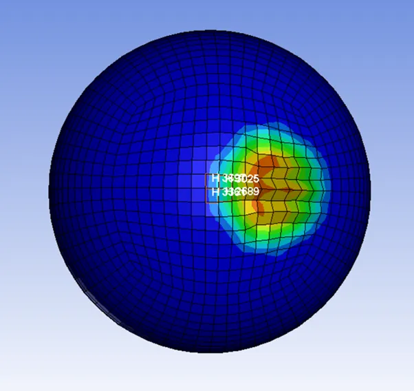
Figure 4.8_element under analysis
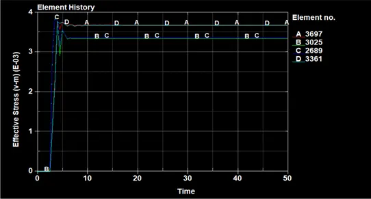
figure 4.9_indevidual element effective stresses
Maximum stress (Average of maximum stress for each element) = 3.5778 x <!-- [if gte msEquation 12]>
Resultant acceleration for Head_Accelerometer. (Node 25679)
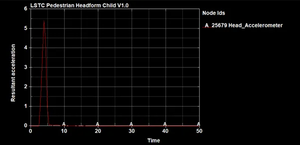
Figure 5.0_Resultant acceleration for Head_Accelerometer. (Node 25679)
Head Impact Coefficient calculation:
Head accelerometer data is calculated for peak acceleration to quantify the effect of collision.
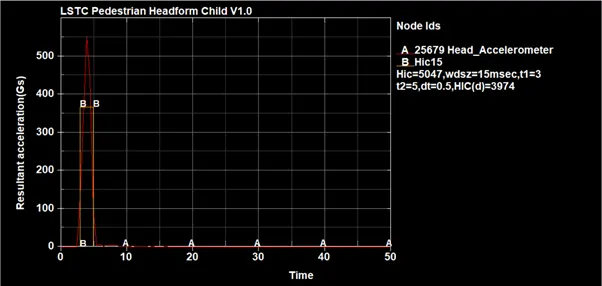
Figure <!-- [if supportFields]> SEQ Figure \* ARABIC <![endif]-->5.1<!-- [if supportFields]><![endif]-->_HIC15and HIC(d) value from resultant acceleration.
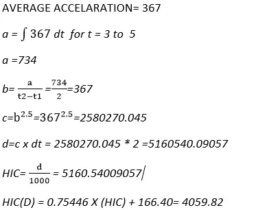
HAND CALCULATION:
|
AGV. ACCELERATION |
TIME PARAMETERS |
Ls PrePost calculation |
Hand calculation |
||||
|
t1 |
t2 |
t3 |
HIC |
HIC (D) |
HIC |
HIC (D) |
|
|
367 |
3 |
5 |
0.5 |
5047 |
3974 |
5160.54 |
4059.82<!-- [if !supportAnnotations]--><!--[endif]--> |
COMPARISON :
We compared stresses and strains experienced by head foam for both the cases with wall and with hood tabulate them and then ploted them to understand the behaviour
here element under analysis for head foam is #E3026 for rwall impact
and element under analysis for head foam is #E2695 for hood impact
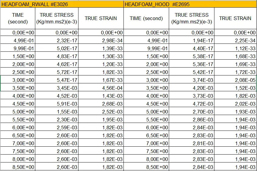
Table 1.1_stresses and strain of head foam impact with Rwall and Hood wrt time
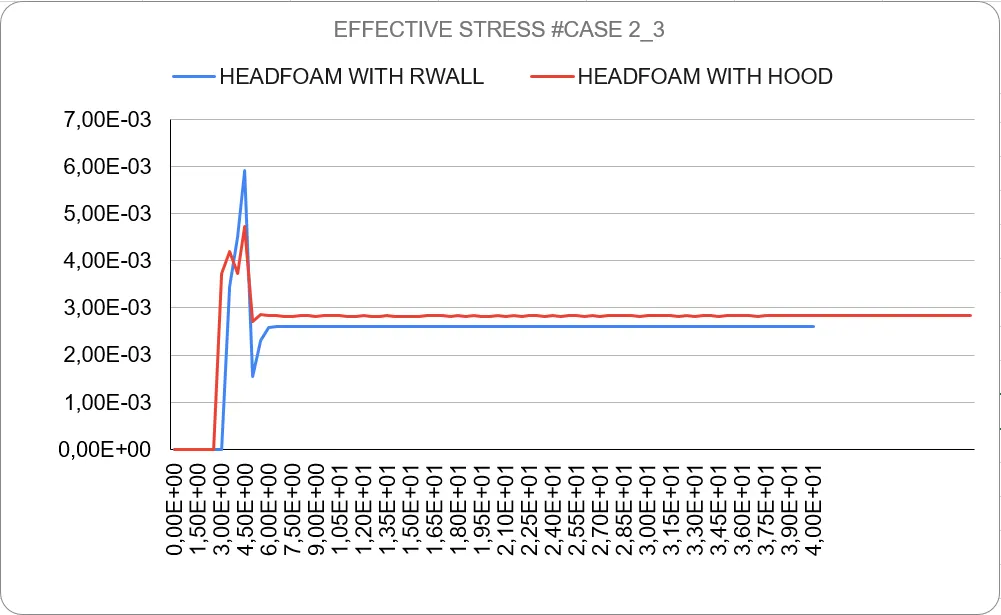
Figure 6.1_effective stresses of head foam with Rwall and hood wrt time
here we can see that stress on head foam when impact with the wall is greater than stress of head foam impact with the hood
Max stress (Hood)= 4.72E-03 kg/mm.ms2
Max stress (Rigidwall) = 5.91E-03 kg/mm.ms2
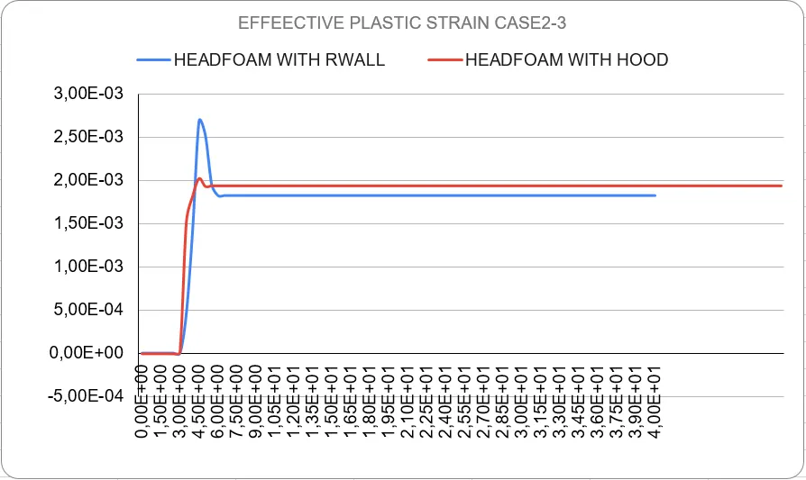
Figure 6.2_Effective Plastic Strain of Headfoam with Rwall and Hood
when the head foam impacts on rigid wall strain is high compared to when it impacts with Hood
Max strain (Hood) = 2.68E-03
Max strain (rigid wall )= 2.02E-03
Clearly, damage to head foam is significantly more in the case of Impact with Rigidwall