Week 4-1D Element Creation Challenge
Objective:
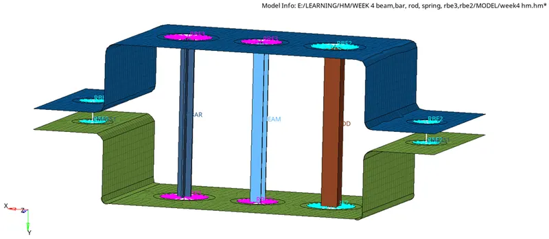
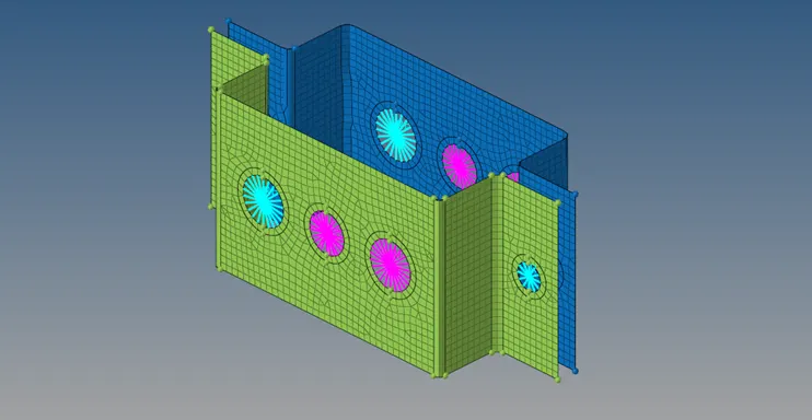
To take out mid surface and mesh the model with average element length of 5 units .
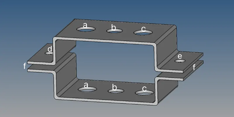
To create the 1D element for given component with given cross section and DOF
Rod element - Translational DOF should be constrained with RBE2 link (at A)
Beam element - All elements should be constrained with the RBE3 link (at B)
Bar element - Constrain only X and Y DOF's with RBE3 link (at C)
Apply the mass of magnitude 10 with RBE2 link (at D & E)
Join the two components with Spring elements (at F)
Refer image :
Why do we required mid surface when we can mesh the model with 3D mesh
We can create 3D mesh on uniform thickness components . which can capture the geometry but it will create too many nodes and elements , which will increase the storage consumption and processing
These efforts can be reduced . if we use mid surface , mesh this , and assign thickness to this . it wil represent the geometry similarly and will only contain 3D hexa , tetra elements ,without affecting the accuracy
Why we use 1D elements :
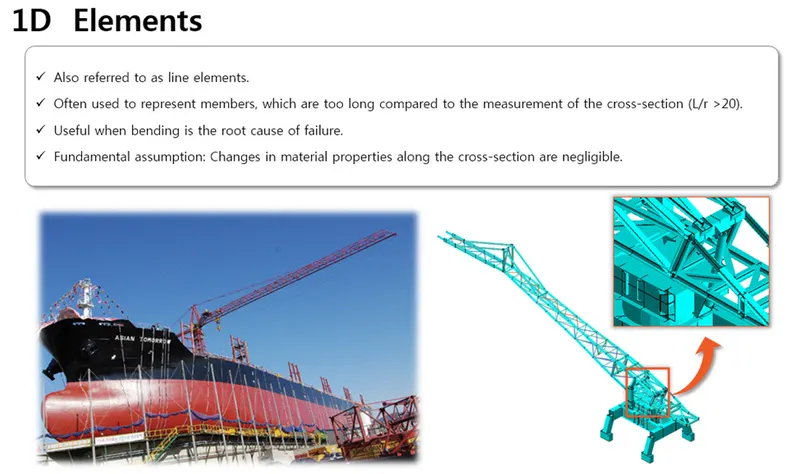
one of the major advantages of 1D elements is that they allow to display directly the bending which is one of the root of failure in structures with long member structures.
Introduction :
PROCEDURE :
Import the model :
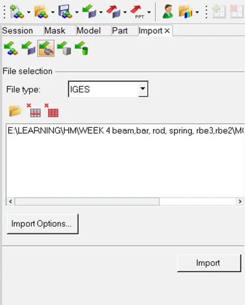
model provided to us is in IGS format so we will goto import solver deck >> import >> import geometry >> file type : IGES >> locate file : ---.IGS >> import.
If model is not visible use fit in option available on top ribbon bar , now we can see the model .
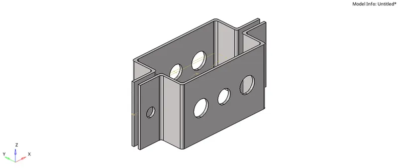
RENAME THE PARTS :
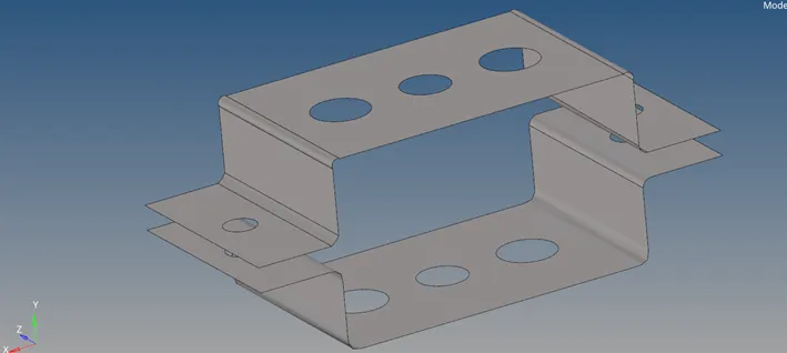
For ease in understanding we will rename the two parts as UPPER GEOM and LOWER GEOM
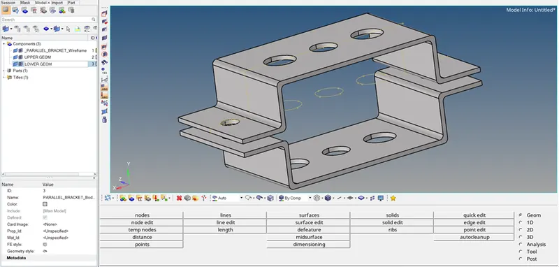
HIDE LOWER PART :
Now we will focus on one part . I.e we will only keep the upper part in screen and lower part we will hide for the time being
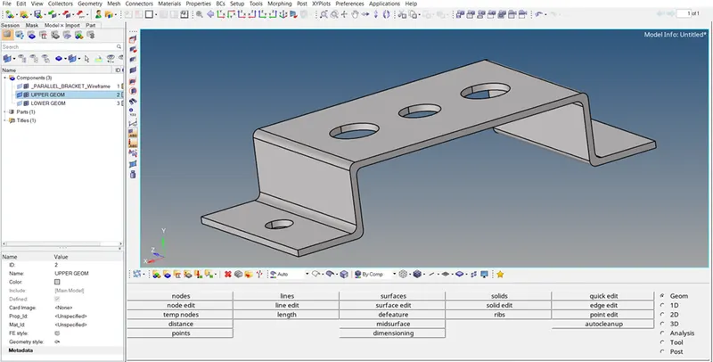
EXTRACT MID :
First we will extract mid from UPPER GEOM .
to do so GEOM >> MIDSURFACE >> AUTO MIDSURFACE ,AUTO EXTRACTION >> IN SURFS [SELECT SURFACE WHICH ARE VISIBLE ]
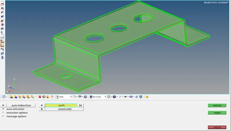
Similarly extract mid for lower bracket by hiding upper bracket and keeping only lower bracket in the screen
CREATE MATERIAL CARD :
To do so go to MODEL BROWSER >> R CLICK >> CREATE >> MATERIAL
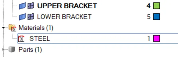
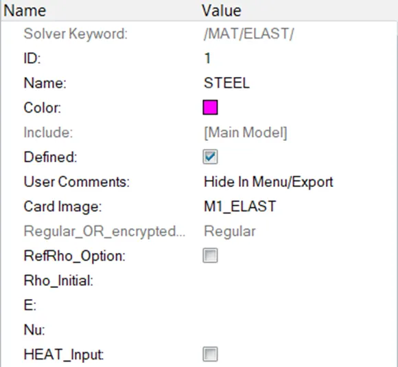
We rename the CARD , SELECT CARD IMAGE , here we have not specified E, RHO , Nu . which should be specified in actual situations
CREATE PROPERTY CARD :
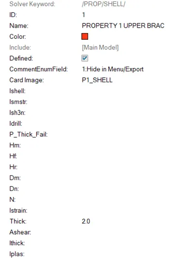
We will create 2 property card for the two brackets to create these goto model browser >> create >>property

Click on these cards and name them ,and assign appropriate thickness to them . in this case 2 mm thickness for upper bracket and 2.5 mm thickness for lower bracket
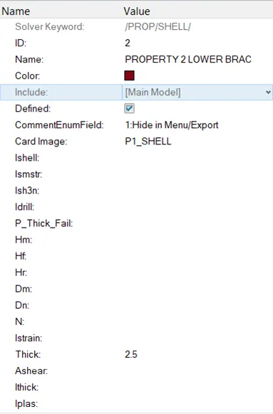
Once property cards are created we have to assign these material and property cards to respective components
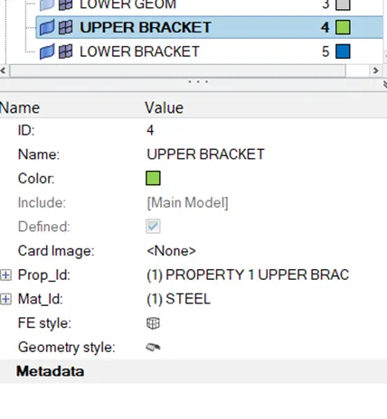
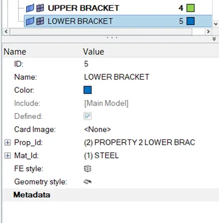
Now that components are properly described we can change the colours of the components i as we want.
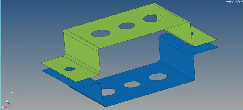
MESH PREPRATION :
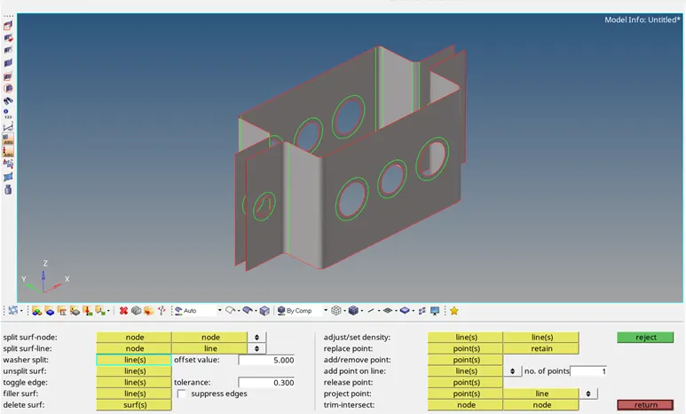
Create washer split :to create washer split goto QUICK EDIT . Here you can find washer split option in it select lines with the offset of average element length
After washer splits has been created it will look as below.
MESHING :
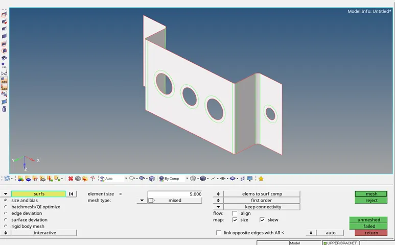
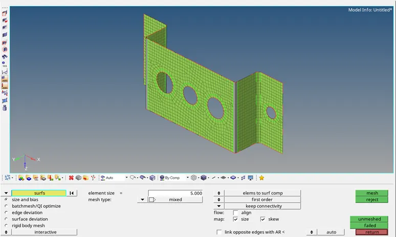
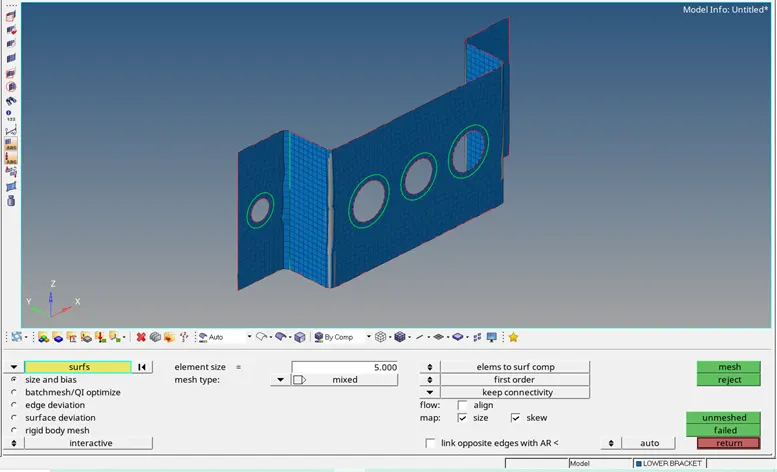
Mesh the upper and lower model individually with element size = 5 ,mesh type = mixed
ORGANIZE COMPONENTS:
Make sure that every element or component should be assign to its respective component card
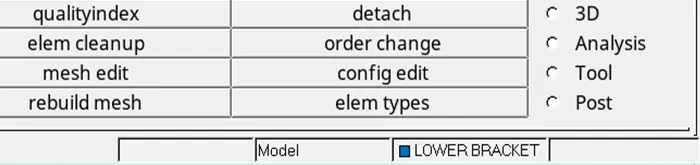
Note : current component should be noticed even when you create mesh . It is shown on bottom right corner of the hyper mesh interface
If current component is different .mesh will associate with that component
CREATE RBE 2 AND RBE 3 ELEMENTS :
RBE2 : GOTO 1D >> RIGID >> CREATE >> INDEPENDENT : CALCULATED NODE >> DEPENDENT : SELECT MULTIPLE NODES >> EMENT TYPE : RBE3 , RISTRICT : TRANSLATION DOF : 1,2 ,3
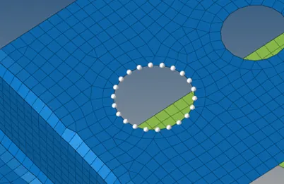

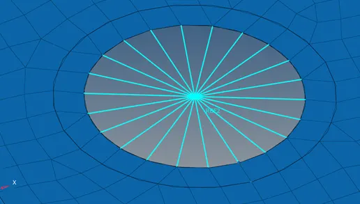
It will create rbe 2 element , you can assign a componenr to this element .
RBE 3: 1D >> RBE3 >> CREATE >> DEPENDENT : CALCULATED NODE >> INDEPENDENT :MULTIPLE NODES >>DOF (AS PER ASKED )>>ELEMT TYPE : RBE3 .
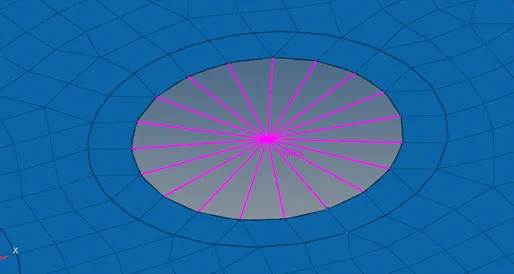
Similarly create other rbe2 and rbe3 as per asked
CREATE BEAM ,ROD , BAR ELEMENT WITH SPECIFIC SECTIONS
First we will create sections : (Note: use optistruct profile. as some sections are only available in optistruct )
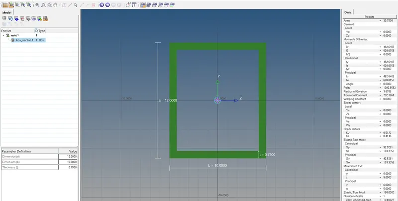
Box section for rod element goto hyper beam >> standard section >> standard section libnrary : hyper beam >> STANDARD SECTION TYPE : THINWALLED BOX >> CREATE

It will open section in hyperbeam , enter the given dimensions for this section
In hyper beam interface we will give dimentions to the box section as below
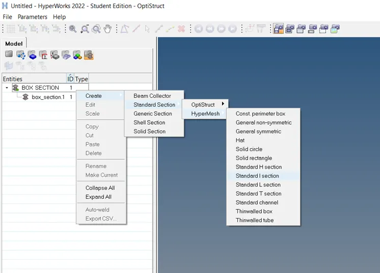
Rename auto 1 to box section then we will create create next section to do so R CLICK ON BOX SECTION >> CREATE >>STANDARD SECTIONS >> HYPER MESH >> STANDARD I SECTION .
 \
\
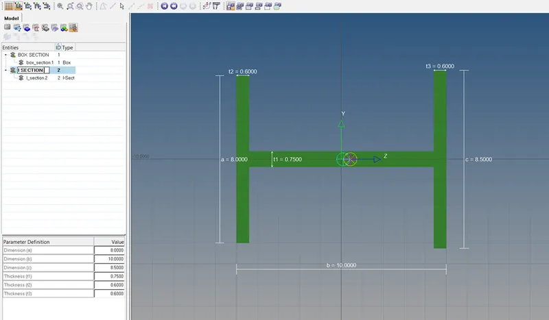
Give the dimentions to this section and rename it as below .
Similarly we will create third section which is cross section
R CLICK I SECTION >> CREATE >>STANDARD SECTION >> OPTISTRUCT >>CROSS
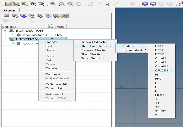
Give respective dimensions
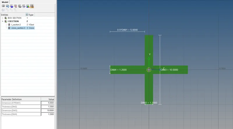
CREATE PROPERTIES FOR EMEMENTS :
we have to crteate 3 properties for three elements of rod beam , bar .
Create rod property:
Assign material , card image : prod ,and section : box section.
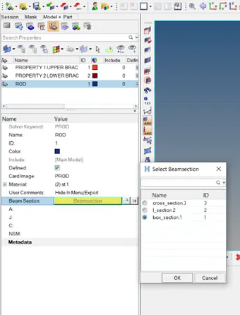
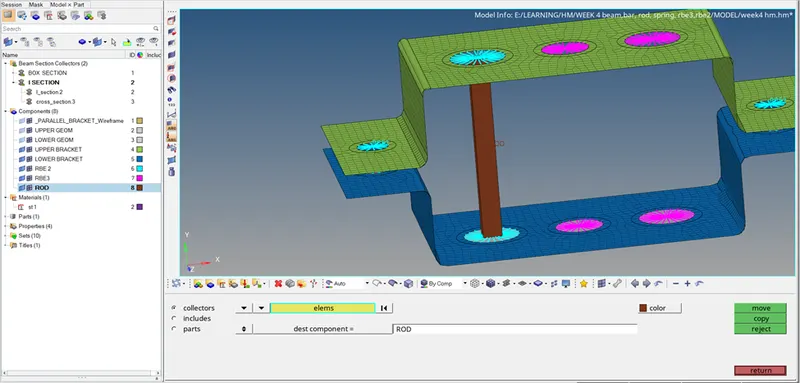
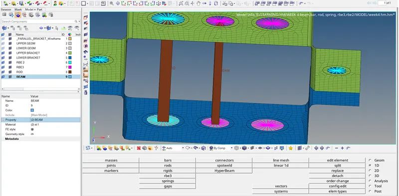
Create rod element to do so goto 1D >>ROD >> ELEM TYPES : CROD , PROPERTY : ROD , PICK TWO ELEMENTS .
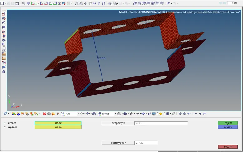
CREATE NEW COMPONENT FOR ROD
Assign prorerty : rod , material :steel , and name it.
This will create rod element with box section as shown below.
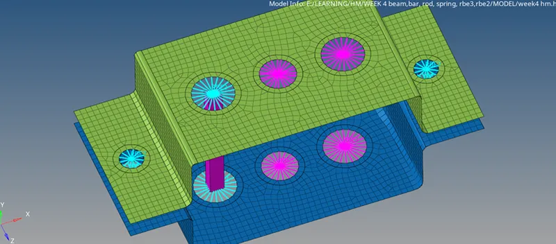
But it has different component assign to it . Move the component to rod through organize
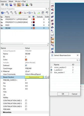
Create new property for beam as shown below
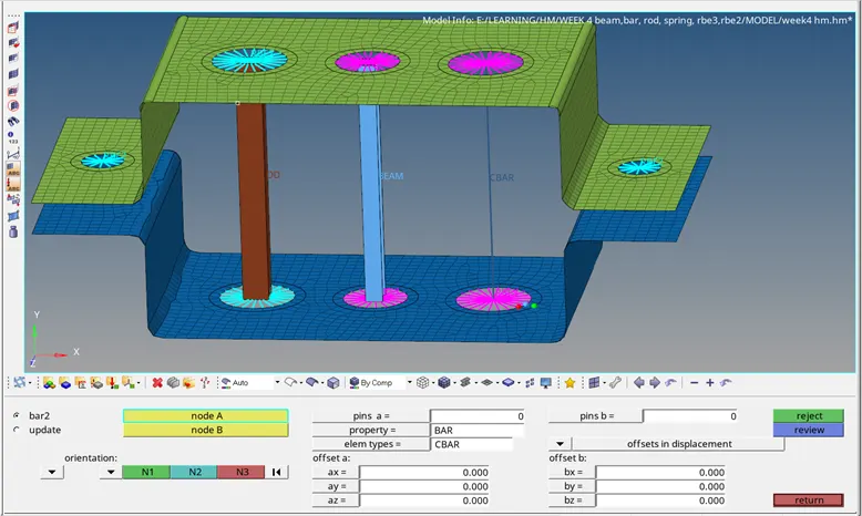
Create beam element through 1D >> BAR >>BAR2 >>PICK NODE A AND B >> PROPERTY : BEAM >>ELEMT TYPE : CBEAM >> FOR SECTION ORIENTATION PIC N1 ,N2 AND N3 .
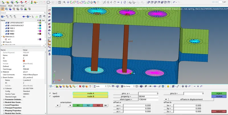
Now create beam component and assign properties to it
Similarly create bar element as below only defference will be here from beam is of ELEMENT TYPE : CBAR
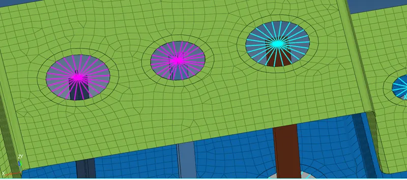
After elements are beam created it will appear as below
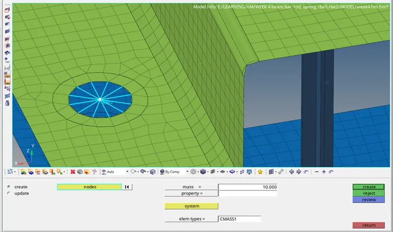
D & E. APPLY THE MASSOF MAGNITUDE 10 WITH THE RBE2 LINK
GOTO 1D >> MASSES >>CREATE >> PICK NODE >> MASS : 10 >> ELEMENT TYPE :CMASS 1 >> CREATE
CREATE SPRING :
TO DO SO GO TO 1D >> SPRING >> PICK THE NODES >> ELEM TYPE : CELAS >> LEAVE OTHER PROPERTIES DEFAULT
For ur convinience we have created a spring components which is auto maticaly get assign to it
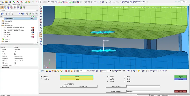
Final model will appear as below .