Week 3 - External flow simulation over an Ahmed body.
Goal:In this challenge, the external flow through Ahmed's body is simulated. Parameters such as lift coefficient and drag coefficient are estimated and verified. The wake area is explored. A grid mesh independence test is performed.
OBJECTIVE:
1. Describe Ahmed's body and its meaning.
2. Explain the reason for the negative pressure in the wake area.
3. Explain the meaning of the separation point.
1. Ahmed's body and its meaning:
The Ahmed body represents the simplified geometry of a bluff-type ground vehicle. Its shape is simple enough to allow accurate flow simulation, but retains some important practical properties related to car bodies. This model describes how to calculate the turbulent flow field around a simple car-like geometry.
The airflow around Ahmed's body captures the basic features of the flow around a car and was first defined and characterized in Ahmed's experimental work. Although it has a very simple shape, the Ahmed body allows us to capture the characteristic features that are relevant to the bodywork in the automotive industry.
ANSYS is a universal FEA and CFD simulation software. It provides a numerical prediction of system behavior. These numerical predictions need to be verified with experimental data.
This model is also used to describe the turbulent flow field around a car-like geometry. People working in vehicle aerodynamics use the Ahmed body to validate their numerical model because experimental data from wind tunnel testing is available for the Ahmed body. Once the numerical model is validated, it is used to design new car models.
The Ahmed body was originally described by S. R. Ahmed in 1984. As a result, three main features were seen:
1. The recirculation region that forms when the flow separates at the top of the vertical back surface of the model
2. Recirculation area B, which is created due to the separation at the base of the model.
3. The c-pillar vortices, which form as a vortex in the lateral boundary layers, wind up over the sloping edges.
The wake was shown to be highly dependent on the pitch angle. For slope angles less than 12°, the flow remains connected across the slope. The flow is essentially two-dimensional and has low air resistance. Between 12° and 30° the flow becomes much more three-dimensional as c-pillar vortices form. They reach their maximum strength at 30°. Braking resistance increases significantly as the low-pressure cores act on the rear surfaces. After 30°, the flow completely separates from the slope. This results in a sudden drop in drag and weaker c-pillar vortices.
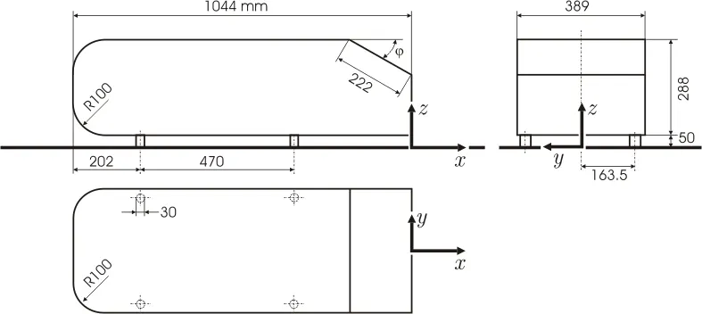
The Geometry of Ahmed's Body is as shown in the below figure.
2. Explain the reason for the negative pressure in the wake region.
The vacuum is caused by the velocity difference applied at a certain Reynolds number and tail angle, which at low Reynolds number, when this pressure difference occurs, the resulting wake increases drag due to the pressure drop behind the Ahmed body, which at high Reynolds number, due to the vortices created, creates a small the amount of pressure pushing the body.
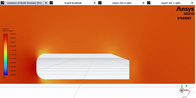
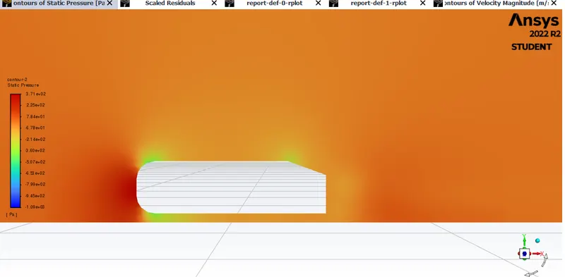
The air almost stagnates upon impact with Ahmed's body, resulting in the air exerting a very high pressure on the front of Ahmed's body. The air stream is then split between the upper and lower surfaces of Ahmed's body. The higher-pressure air on the front surface accelerates as it travels over the curved nose surface of Ahmed's body, causing a pressure drop. This lower pressure creates buoyancy over the surface of the roof as air passes over it. As the air continues to flow and make its way to the rear, the backslope flow separation creates a notch, leaving a vacuum or low-pressure space that the air is unable to properly fill. The resulting lower pressure creates lift and drag, which then acts on the backslope surface.
The following figure shows the pressure thrusting.

3. The meaning of the separation point.
Flow separation or boundary layer separation is the separation of the boundary layer from the surface into the wake. Separation occurs in a flow that decelerates with increasing pressure after passing through the thickest part of the streamline body or passing through an expanding passage.
The separation point defined by the Ahmed body and the flow, the angle alpha depending on which value is on it causes a change in flow direction, the forces required, the lift on the body, the induced drag due to the "tip vortex", at and the critical value of the flow at oblique stalls and reduced lift and drag reduction, all dependent on alpha and Reynolds number.
Geometry:
First, we need to set up the geometry of Ahmed's Body for our simulation.
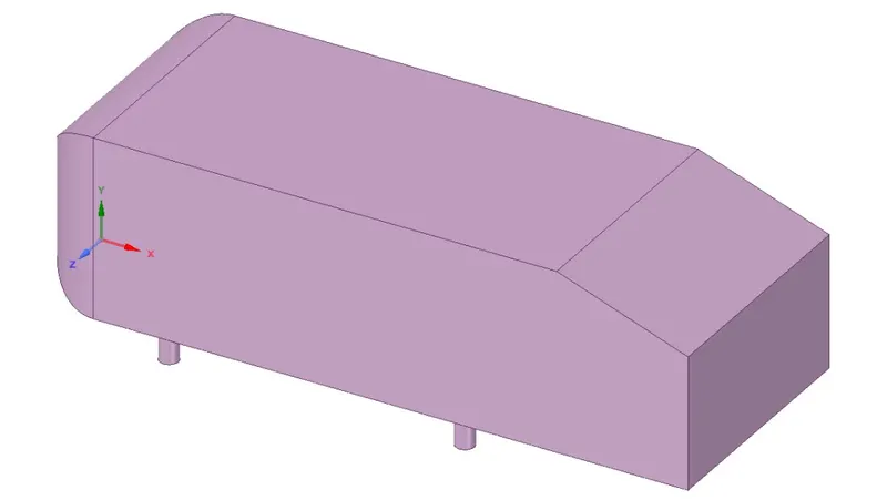
Isometric view of the three-dimensional model of Ahmed body.
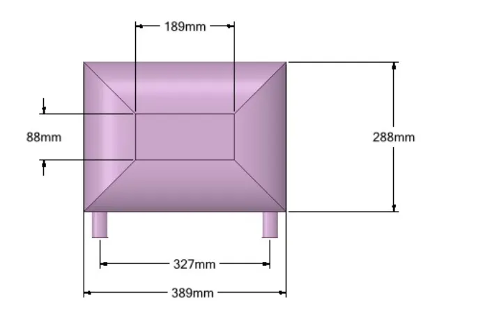
Front view of the Ahmed body.
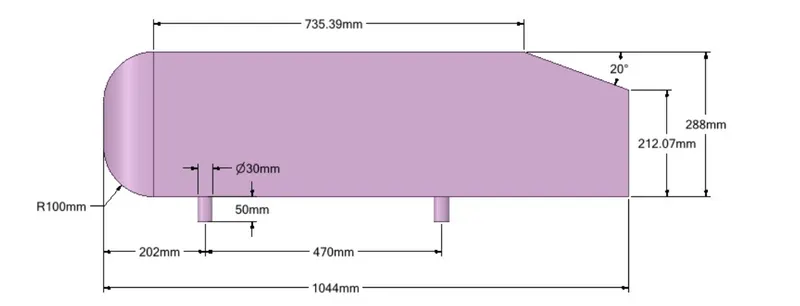
Side view of Ahmed body.
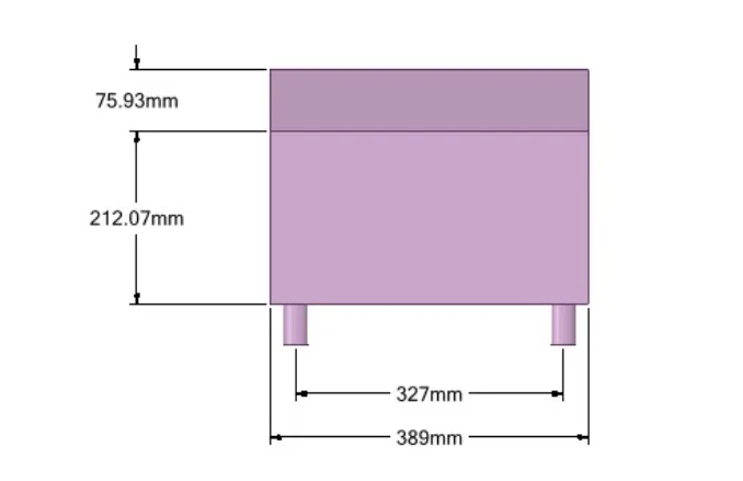
Rear view of Ahmed body.
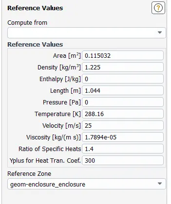
we can also calculate the frontal area and length for reference in solver
Area = 0.115032 m^2
Length = 1.044 m
Creating the enclosures around the Ahmed Body for baseline mesh generation.
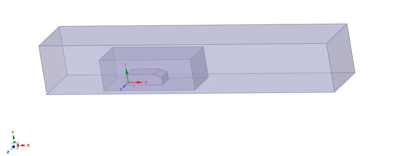
Outer cover
- The outer cover is at a distance of 2 m from the front of Ahmed's body in the X-axis.
- The outer cover is at a distance of 5 m from the back of Ahmed's body in the X-axis.
- It is at a distance of 1 m from the top in the Y axis.
- It's merged at the bottom, which means it's at zero distance.
- From the left and right sides of Ahmed's body, it is 0.5 m along the Z axis.
Indoor enclosure - The inner cover is at a distance of 0.5 m from the front of Ahmed's body in the X-axis.
- The inner cover is at a distance of 1 m from the back of Ahmed's body in the X-axis.
- It is at a distance of 0.5 m from the top in the Y axis.
- It's merged at the bottom, which means it's at zero distance.
- From the left and right sides of Ahmed's body, it is 0.26 m along the Z axis.
Interference region.
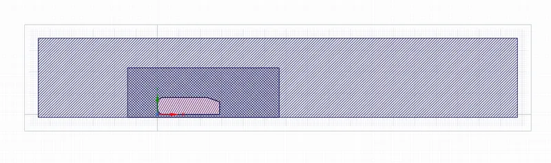
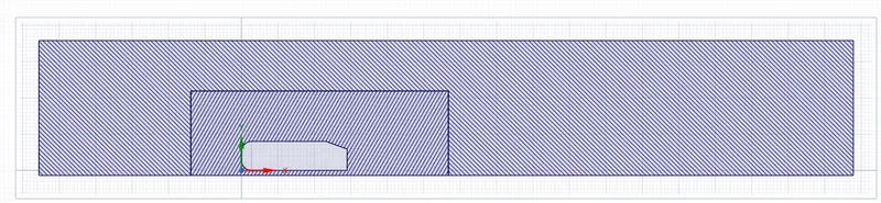
Initially, there was a huge interference between the outer and inner cap, so the network overlaps, which is not acceptable, so to avoid this, we created a shared topology and removed the interference area, so using the interference command after this, we get a good interaction. between the inner and outer closures so that we can get the mesh correctly.
- Y-plus = not used
- Viscous model: K-omega
- 1st box domain =not specified
- 2nd box domain = not specified
- Inflation layer thickness = none
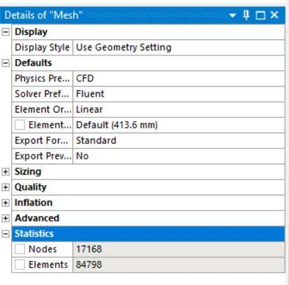
- Elements = 84,798
- Nodes = 17,168
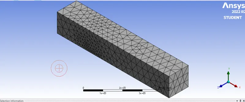
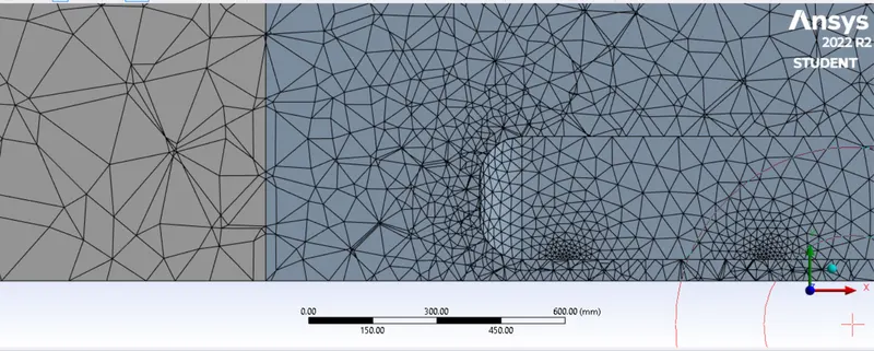
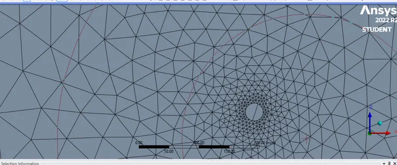
MESH
- It was a base line mesh
SET UP
- in the setup>physics>steady state and density-based solver.
- setup>physics>viscous model>k-omega>ok.
- setup>physics>materials, select air as a flow material>ok
- setup>physics>boundaries>inlet -velocity as 25 m/s, outlet gauge pressure as 0, other conditions will be the default values we are considering>click on ok
- setup>solution>report>definitions>new>force report>drag>drag coefficients>car-wall>select report file and report plot >save/display
- setup>solution>method>Hybrid>initialize
- Result>create>plane>point and normal>ok
- setup>solution>run calculation
DO NOT FORGET TO GIVE REFERENCE VALUES
SOLUTION
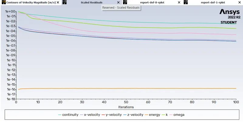
1. Residuals
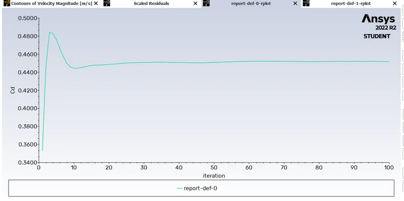
2. Drag co-efficient
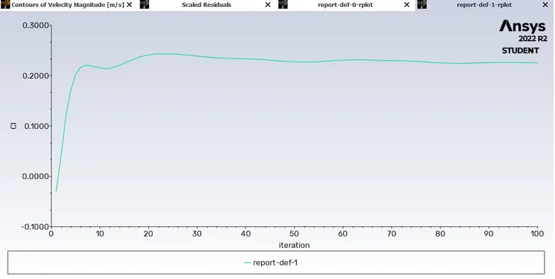
3. Lift co-efficient
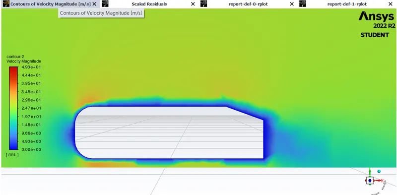
4. Velocity contour
5. Pressure contour
RESULTS:
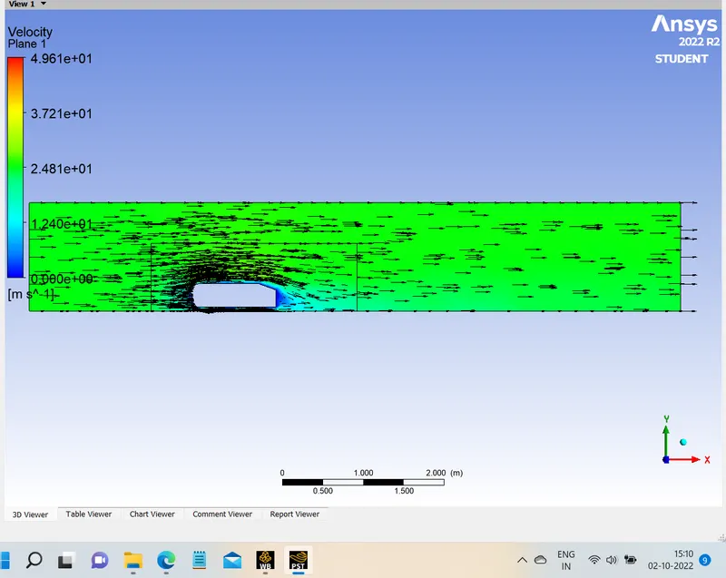
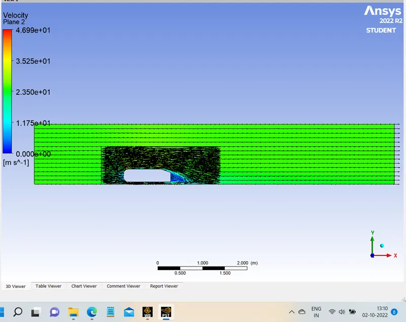
1. Vector on xy plane
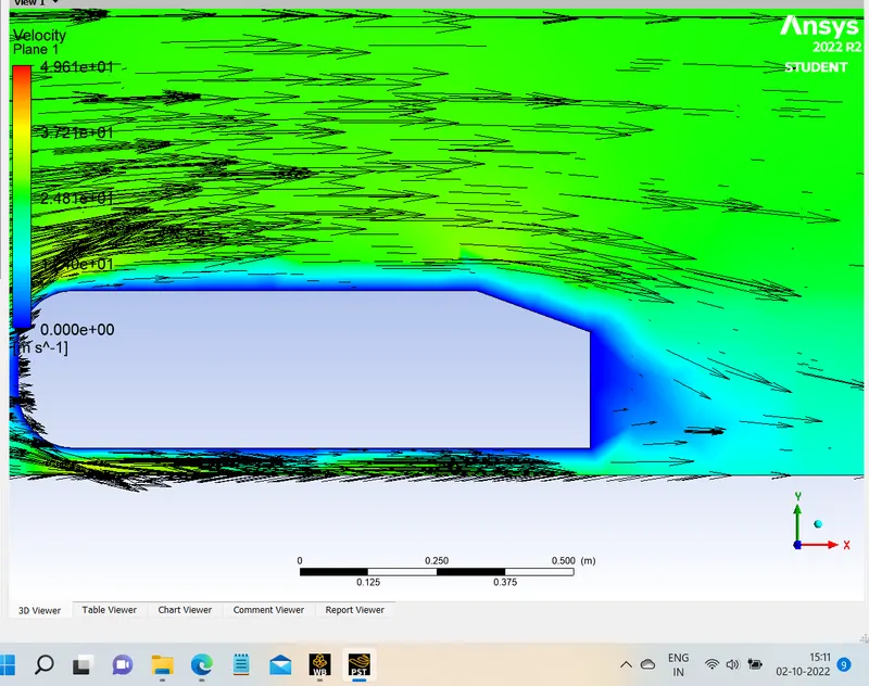
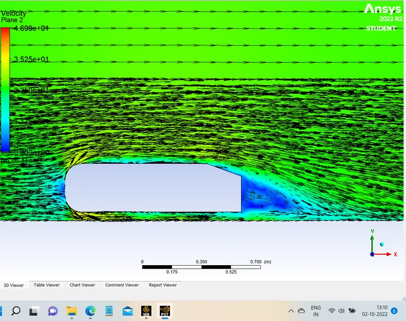
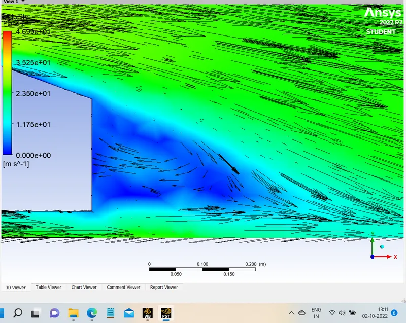
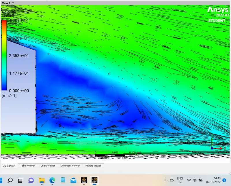
zoomed in for better understanding of vectors
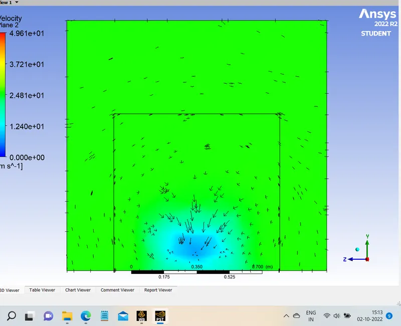
2. Vectors on yz plane 200mm after the ahmed body
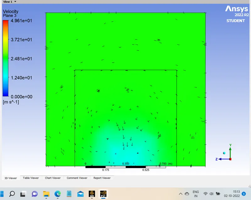
3. Vectors on yz plane 400mm after the ahmed body
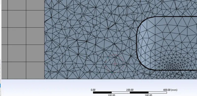
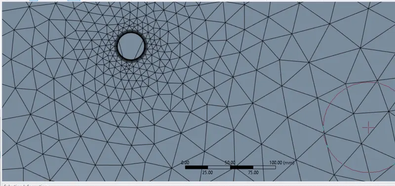
Case 2 : Slightly Refined mesh
- Y-plus = 100
- Viscous model: K-omega
- 1st box domain =100 mm size of hexahedral mesh
- 2nd box domain = 50 mm size of tetrahedral mesh
- Inflation layer thickness = 6 layers, 3.63mm total thickness
- Elements = 212,687
- Nodes = 65,209
MESH
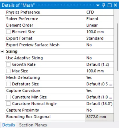
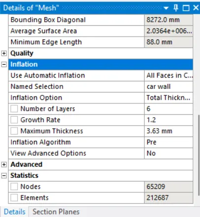
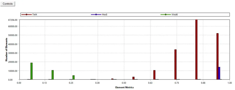
Quality of mesh
SET UP
- same for every case
SOLUTION
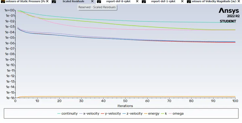
1. Residuals
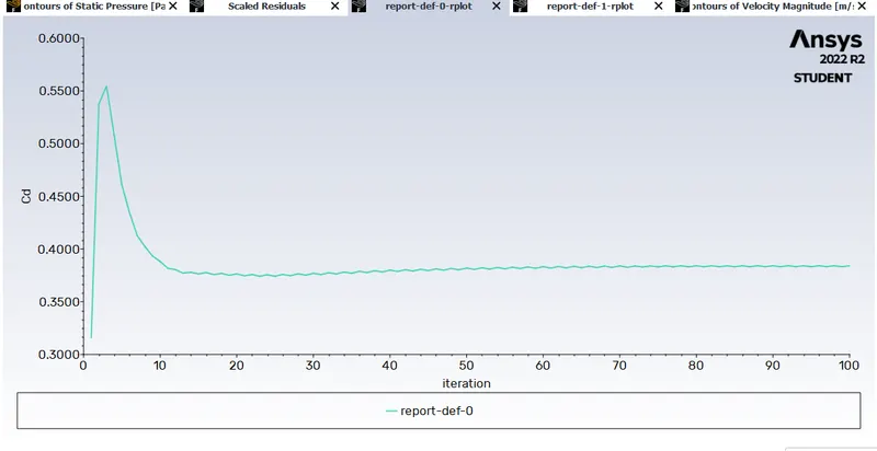
2. Drag co-efficient
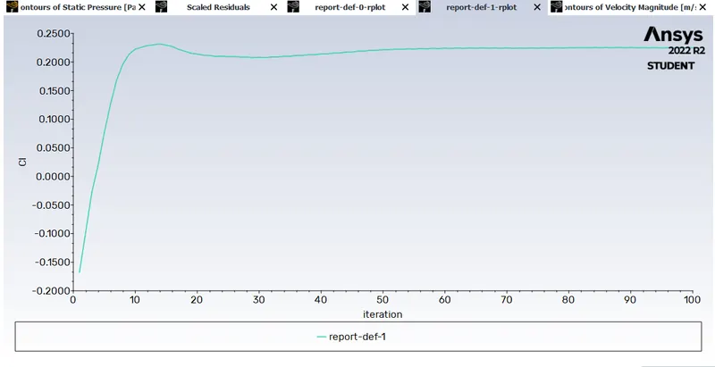
3. Lift co-efficient
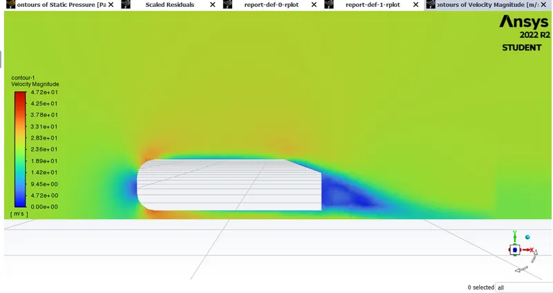
4. Velocity contour
5. Pressure contour
RESULTS:
Vector on xy plane
zoomed in for better understanding of vectors
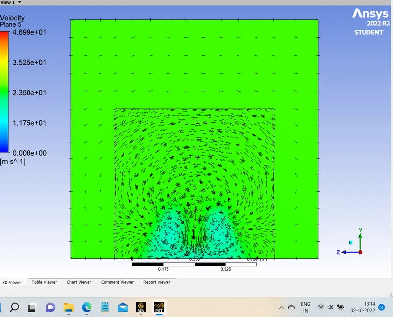
Vectors on yz plane
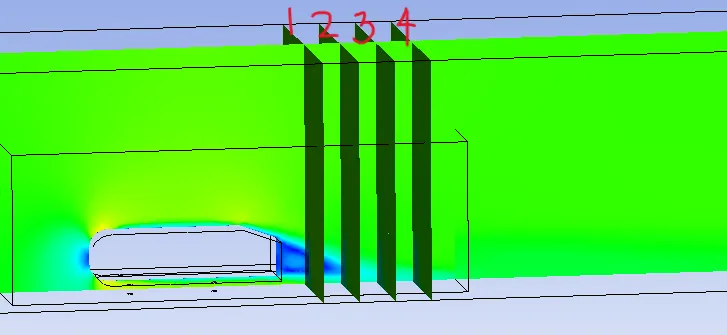
- 200mm after the ahmed body
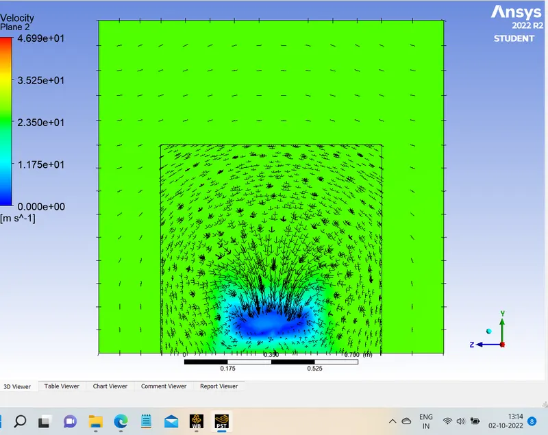
- 400mm after the ahmed body
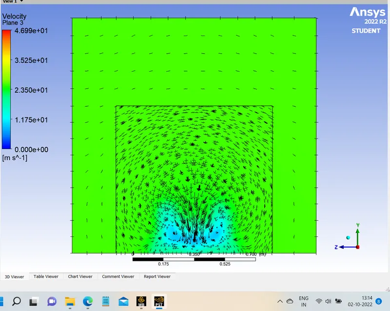
- 600mm after the ahmed body

- 800mm after the ahmed body
Case 3 : More Refined mesh
- Y-plus = 100
- Viscous model: K-omega
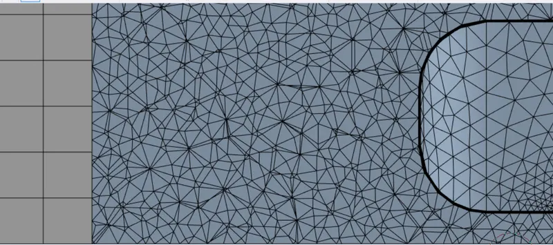
- 1st box domain =75 mm size of hexahedral mesh
- 2nd box domain = 35 mm size of tetrahedral mesh
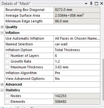
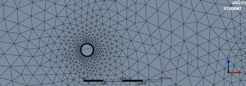
- Inflation layer thickness = 6 layers, 3.63mm total thickness
- Elements = 506,492
- Nodes = 142,253
MESH
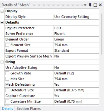
Quality of mesh
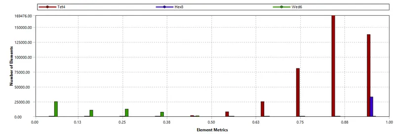
SET UP
- same for every case
SOLUTION
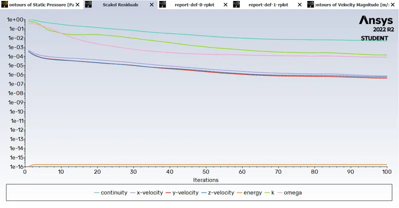
1. Residuals
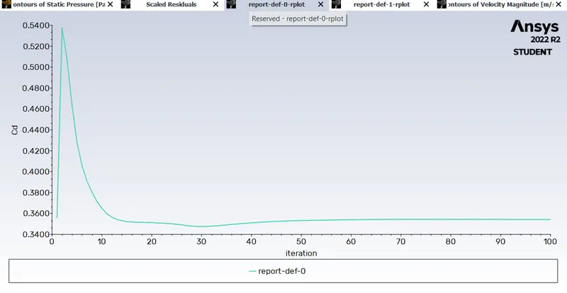
2. Drag co-efficient
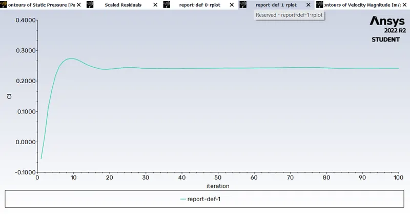
3. Lift co-efficient
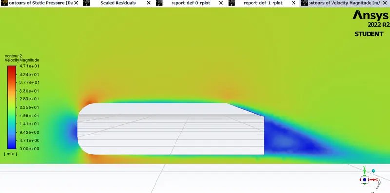
4. Velocity contour
5. Pressure contour
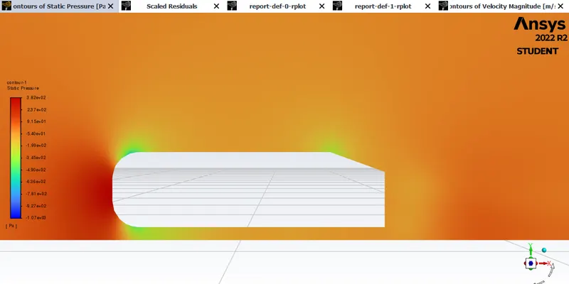
RESULTS:
Vector on xy plane
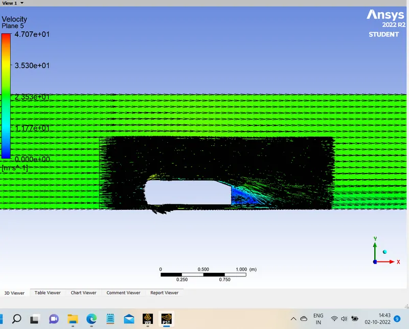
zoomed in for better understanding of vectors
Vectors on yz plane
- 200mm after the ahmed body
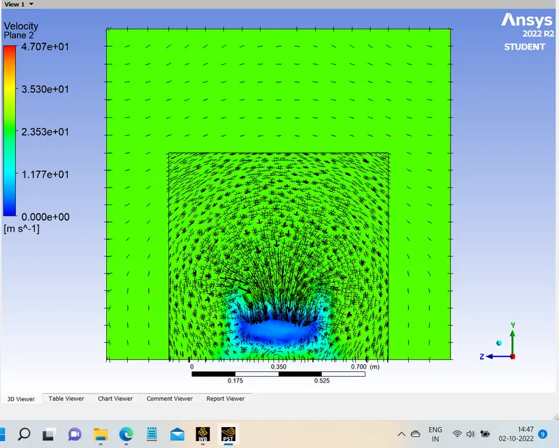
- 400mm after the ahmed body
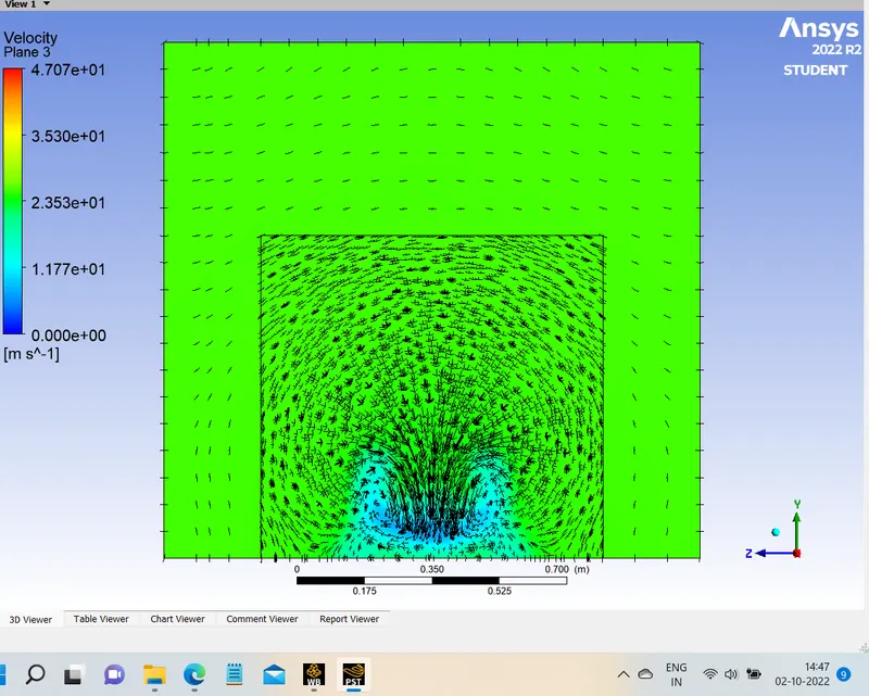
- 600mm after the ahmed body
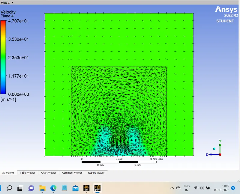
- 800mm after the ahmed body
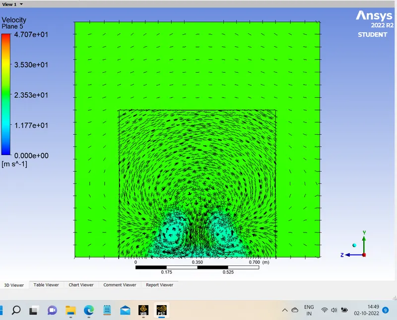
STREAMLINE VIEW :
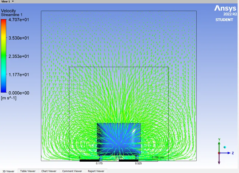
Negative pressure gradient
As the velocity of the fluid increases, the pressure decreases. The wake region is formed due to the adverse pressure at the rear end causing the boundary layer to separate from the body. The shear stress and wall velocity become zero and a wake begins to form. These wakes are nothing more than small eddies that create negative pressure. These create velocity circulation and induce drag forces.
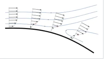
Separation occurs due to the adverse pressure gradient that occurs as the flow expands, causing an extended area of separated flow. The part of the flow that separates the recirculation flow and the flow of the central region is called the dividing streamline. The point where the dividing streamline rejoins the wall is called the reattachment point. As the flow continues downstream, it eventually reaches an equilibrium state and has no reverse flow. When the boundary layer separates, its remnants form a shear layer, and the presence of a separated flow region between the shear layer and the surface modifies the external potential flow and pressure field. In the case of profiles, adjusting the pressure field results in an increase in pressure resistance.
Comparision.
| ELEMENTS | NODES | Cd | Cl | |
| CASE 1 | 84,798 | 17,168 | 0.451 | 0.232 |
| CASE 2 | 2,12,687 | 65,209 | 0.381 | 0.233 |
| CASE 3 | 5,06,492 | 1,42,253 | 0.339 | 0.240 |
Conclusion
1.From the baseline simulation run, the post-CFD results gave inaccurate results in the area of mesh overlap.
2.The network independence test shows the best results close to the experimental data. By refining the mesh size with a factor of y+, the error is significantly reduced.
3.The value of y+ is chosen between a stable range to ensure correct prediction of velocity and pressure contour plots.
4.Flow separation and the appearance of vortices become more pronounced as y+ increases. As can be seen in the baseline meshing, no wake formation is captured correctly, while refining the mesh, the flow is captured correctly. (Y+ plus values were changed and recorded, but not in the report)
5.The pressure in Ahmed's body changes. The pressure in front of the body is positive because that is where the flow first contacts the body and stops. At the corner, the flow accelerates, reducing the pressure.
6.The reason for the negative pressure in the wake area is flow separation, recirculation flow. It is a phenomenon that generally occurs when air moving around the body is unable to pass the immediate back of the body, creating an area where there is no air movement, thereby creating a pressure gradient.
7.Since the wake flow is a major contributor to the drag force (pressure drag), the separation point is an important aspect of the flow. The more the flow is attached to the body, the recirculation zone will be smaller and thus the adverse effect of pressure resistance will be reduced, improving the fuel efficiency of the body.