Week-11 : Discretization of 3D intake manifold using GEM-3D
IC-Engine Calibration Using GT-Power and GT-Suite
Objectives:
-
1. To Explore the "Tutorial- single cyl DI". In Case Setup, considering case-1 with discretization length 40 mm & case-2 with discretization length 0.1 mm for intake runner. Comparing both the results for the following paramaters i.e. Parameters-Torque, BSFC, max cylinder pressure and simulation time.
- 2. To Explore tutorial No-2 (GEM3D) - “Building intake manifold from STL model”.
1. To Explore the "Tutorial- single cyl DI".
Model:
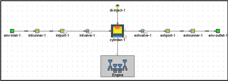
The first step is to create a discretization length as a parameter and then we can keep varying the discretization length for different cases in the CaseSetup.
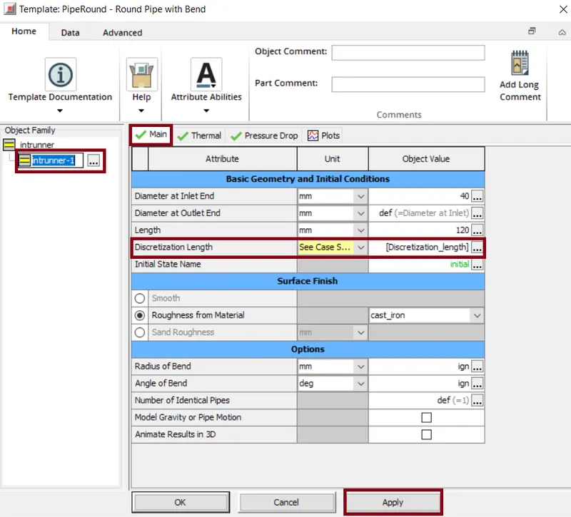
In the CaseSetup, two cases are created in which case-1 is set with default values i.e. RPM= 3600 and Length(Descretization Length)= 40 mm. For case-2, the RPM is constant i.e. 3600rpm and Length(Descretization Length)= 0.1 mm.
Results:
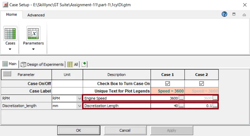
Here the simulations are carried out for two different cases i.e. Discretization length=40mm and 0.1mm. The RPM=3600 is maintained constant for both the cases.
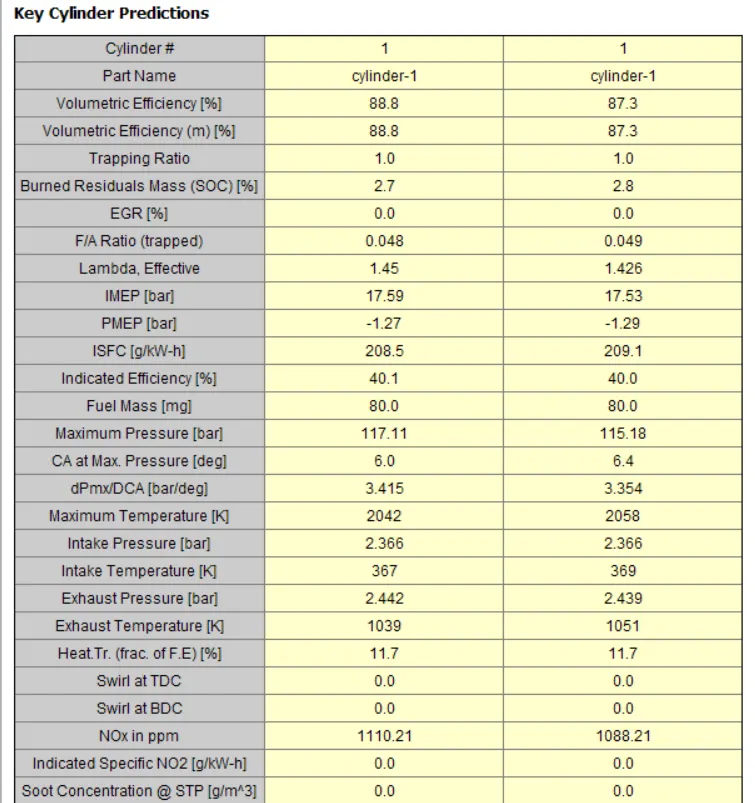
As the model used here is a single cylinder and we changed only the intake runner there is no much impact on varying the discretization length.
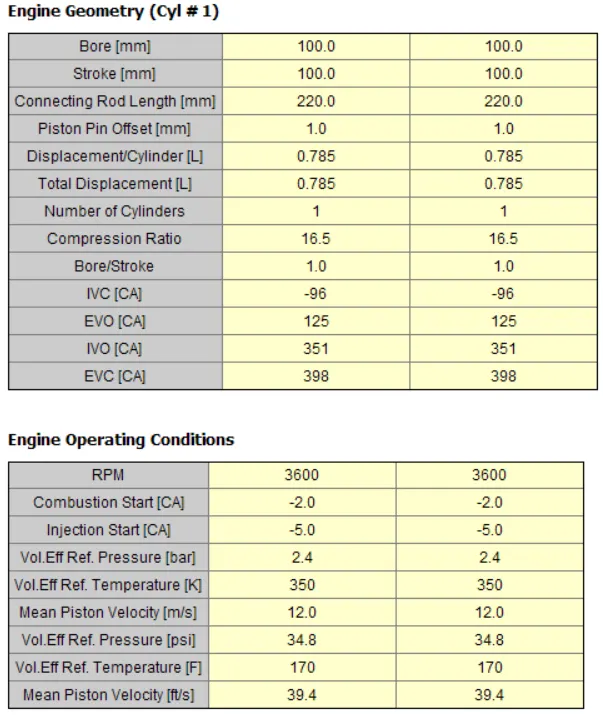
From the below table we can observe that there is no much difference in the BrakePower value for both the cases. There is a slight variation in the Air Flow Rate i.e. for 40mm=179.5kg/h and for 0.1mm=176.5kg/h. Also the difference bwtween the two cases for BSFC is also minimal.
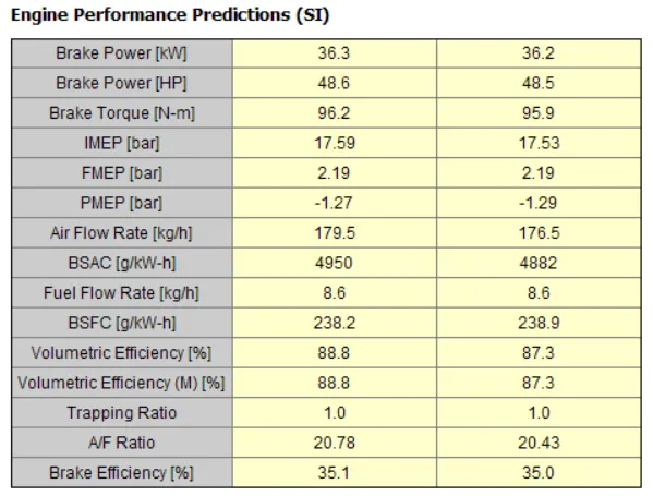
The maximum pressure when the discretizationlength =40mm is 117.11bar and when the discretizationlength =0.1mm is 115.18bar.
Simulation Run Time:
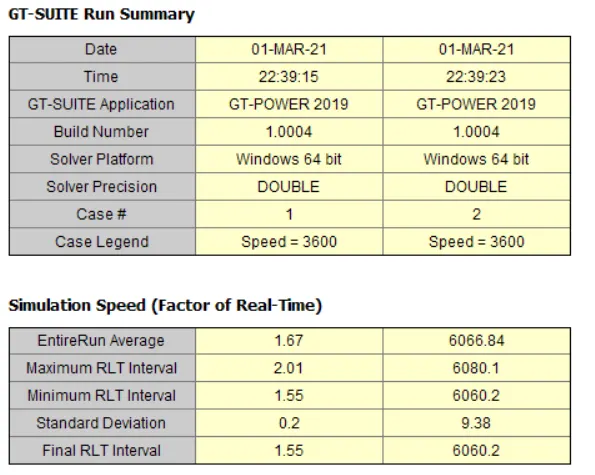
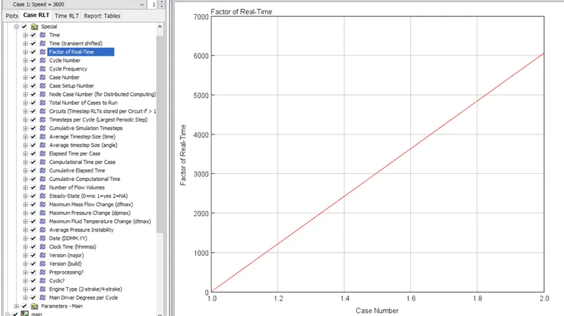
The run average time for discretization length=0.1mm is very hign when comapred to first case. The Factor of Real time plot shows the variation for both the cases.
Conclusion:
| Discretization Length= 40mm | Discretization Length= 0.1mm | |
| Torque(N-m) | 96.2 | 95.9 |
| BSFC(g/kW-h) | 238.2 | 238.9 |
| Maximum Cylinder Pressure(bar) | 117.11 |
115.18 |
2. To Explore tutorial No-2 (GEM3D) - “Building intake manifold from STL model”.
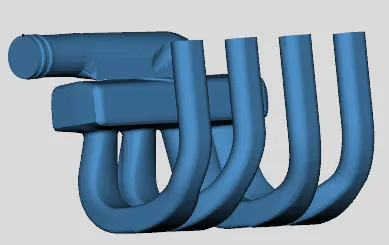
Inorder to open the existing geometry, we need to open GT-SpaceClaim > Import the "phelum" file i.e. the STL file of the geometry.
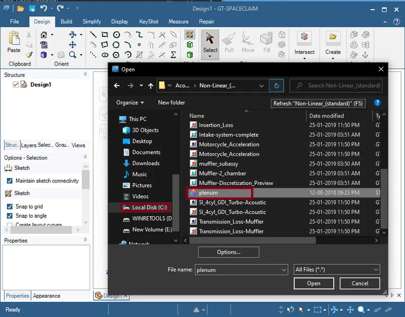
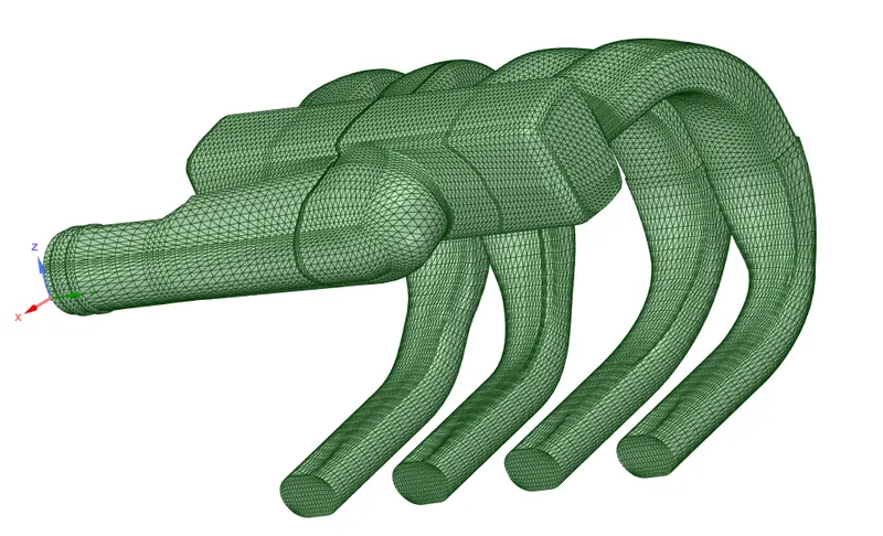
In space Claim we can do some modifications as required. To extract the fluid volume we need to go to GEM-3D.
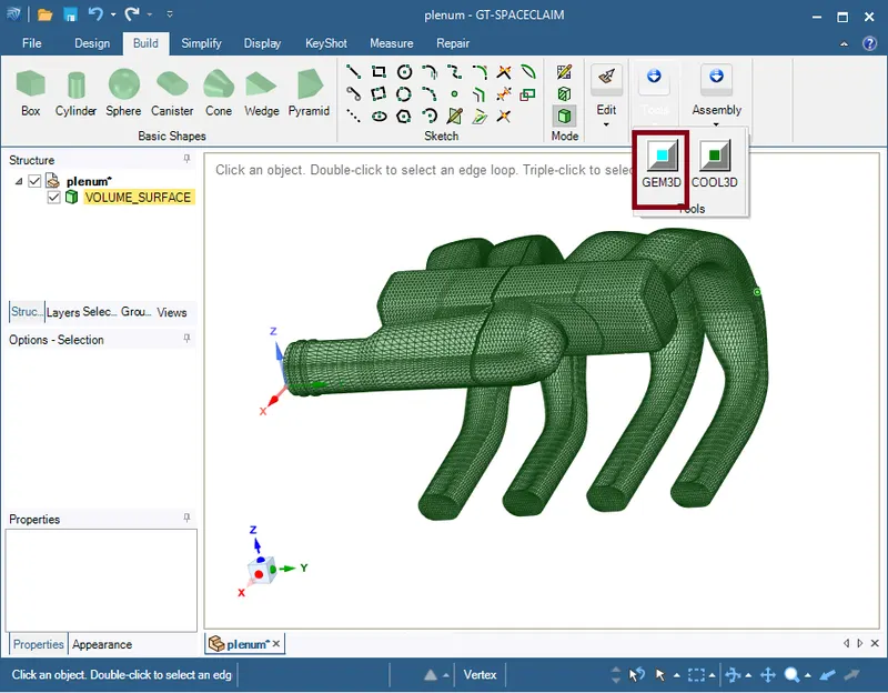
Once the geometry opens in GEM-3D, as we are working on Engine, Intake, Exhaust system we need to select "GEM3D(.gem)".
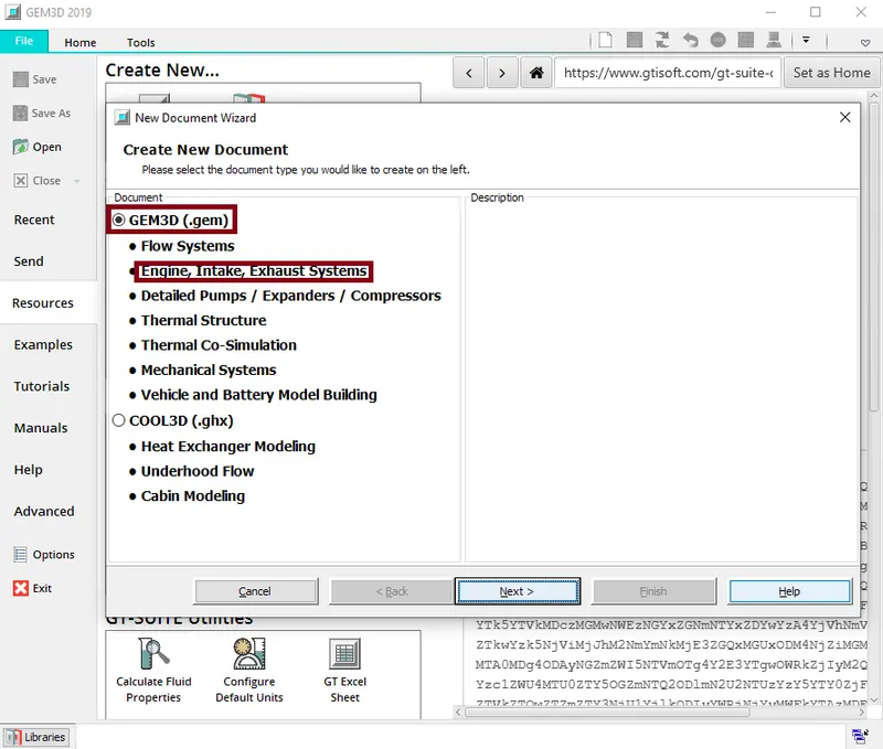
GEM-3D creates a mesh shape component from the imported shape and adds it to the model. This is a cadd-model, i.e. fluid domain. And now we need to translate it into different individual components.
Separation of sections according to treatments:-
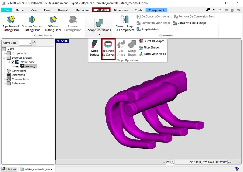
Now the above geometry is divided into small volumes. To do this we need to go to 'Convert' from the top toolbar > select geometry > click on 'Shape Operations' > select "Separate By Curves". Then set the tolerance value to 1.
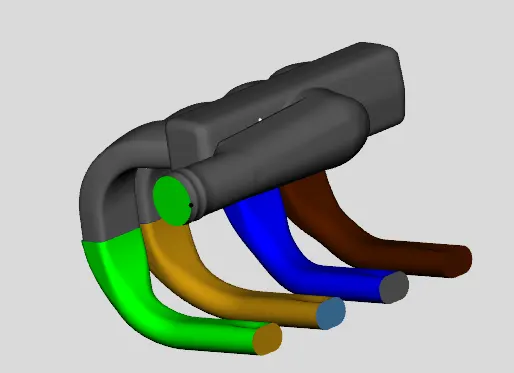
Now select the holes where the air exchange takes place and remove them.
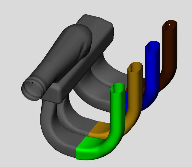
Now we need to split runners and other volumes. For this we use a 3-point cutting plane. Select three points on the bottom surface where the guides join to create a plane. Here we need to set the location so that the plane does not cut the runner. Select the second part of the runner and click "Clip". Now we can see that the runners are different from the plenum.
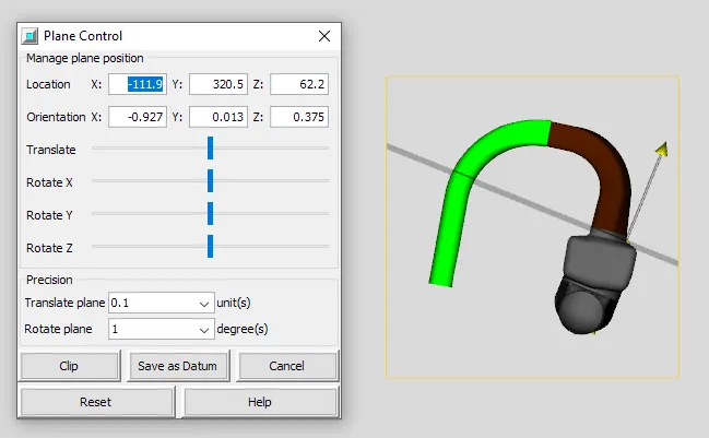
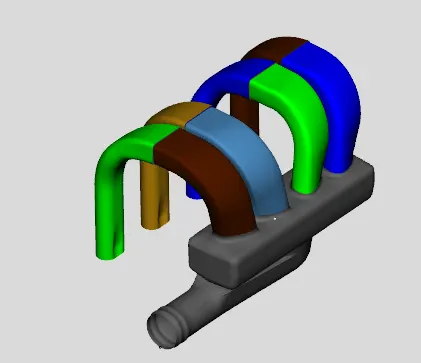
The next step is to convert the gutters into pipes. Select a specific [runner and right-click on it. We get "Convert shape to component".
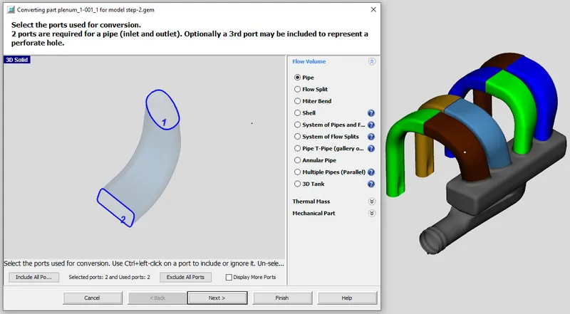
In this step, we specify the bend type, cross section variation and also specify the port size definition, i.e. we measure the approximate diameters for both ports. Pressure, temperature, composition and wall temperatures are specified. Thus, the pipe is generated for the first section of the trough.
I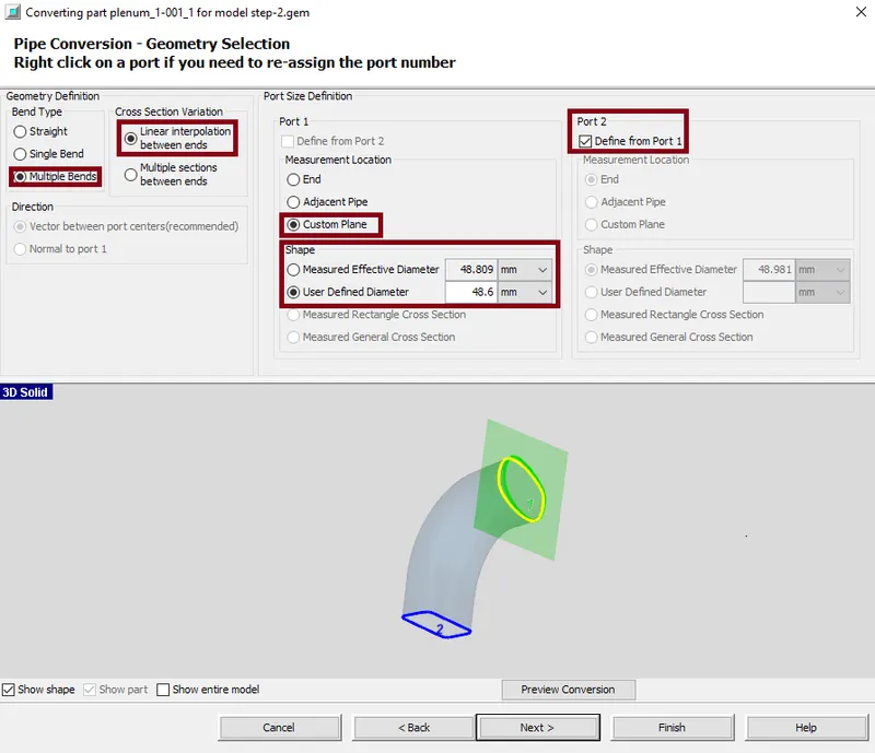
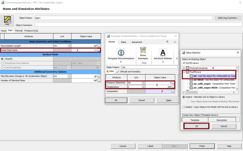
A similar procedure is done for the rest of the 3 runners. Now the first part of all 4 gutters are converted into pipes..
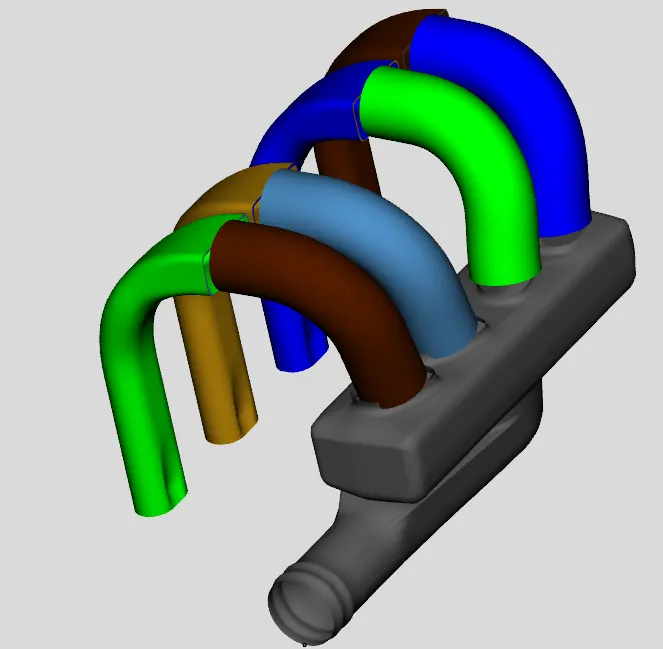
Now we need to convert the second section of runners. Pressure, temperature, composition and wall temperatures are taken into account. Thus, the pipe is generated for the first section of the trough.
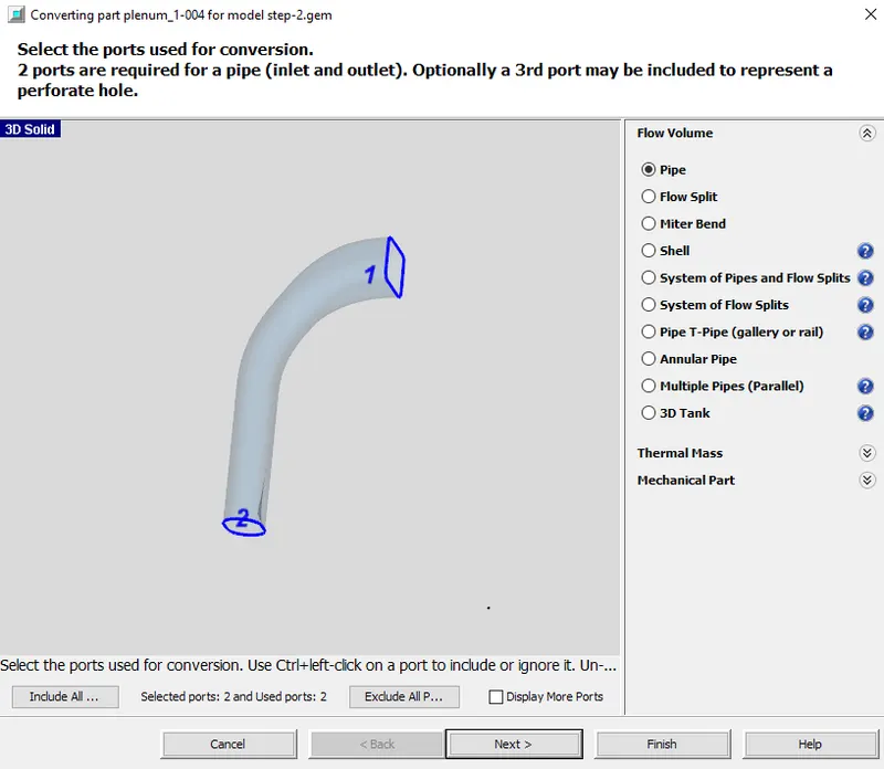
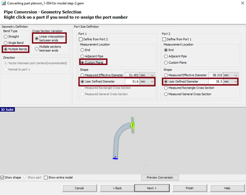
The similar procedure is carried out for rest of the 3runners. Now the second section of all the 4 runners are converted into pipes. Also the extra plane between two sections is deleted.
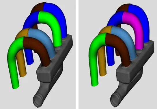
In the conversion process for the runner, the information regarding the curved entry from the pipe was lost. This curved inlet would represent a better flow transition than the default orifice connection, so we manually add a representation of the orifice connection.
Here, right click on the first area of the runner, select port-1 and choose the connection as "OrificeConn". The forward discharge coefficient is specified as a parameter for all 4runners. Discharge coefficient = 0.95.
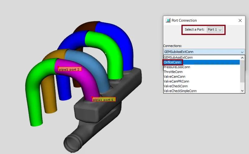
To be clear about the intake and output for the GT, we also need to specify the second area of the guide rails. Enter the port connection in the same way. For the outlets, we add "Sub-Assembly Connection" to clearly see the difference between input and output.
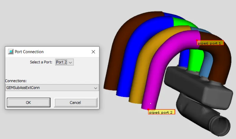
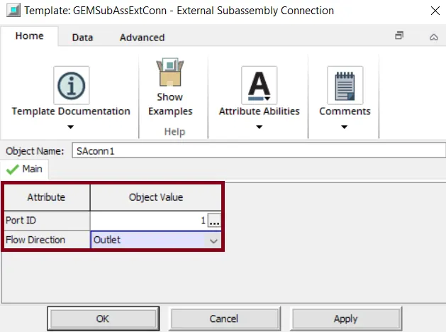
The same procedure is used for the rest of the output troughs by changing the port ID for each output.
Now we need to split part of the pipe. As we can see, there is a certain angle to the pipe in a specific place, we will divide the pipe selection according to the picture. Use the Pipe Normal section plane to select the pipe area.
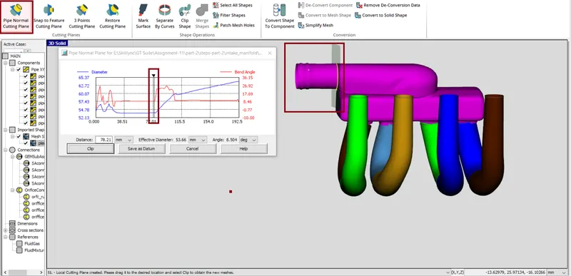
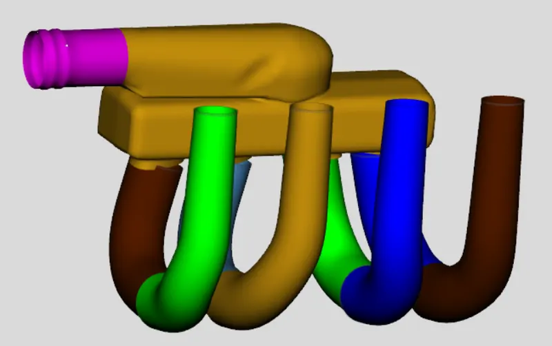
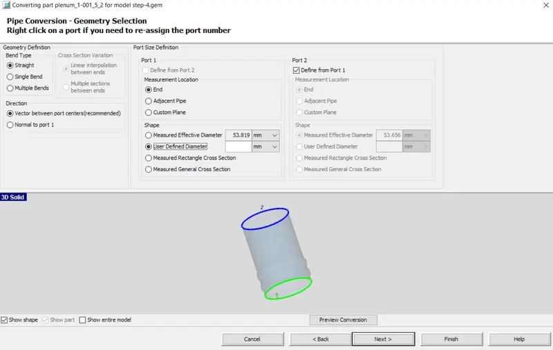
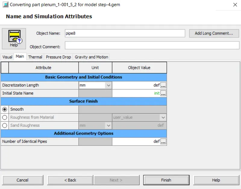
The second part is similarly divided and the parameters are specified in the same way.
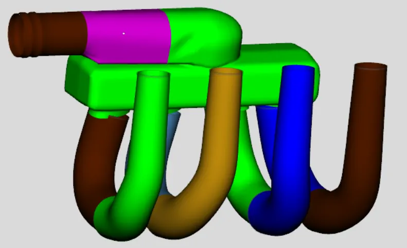
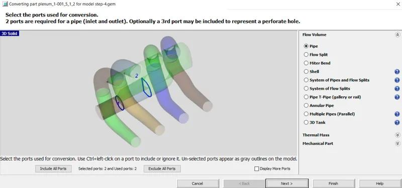
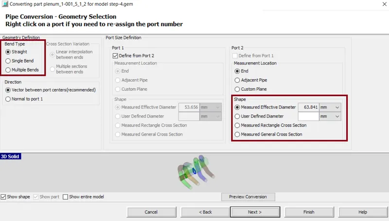
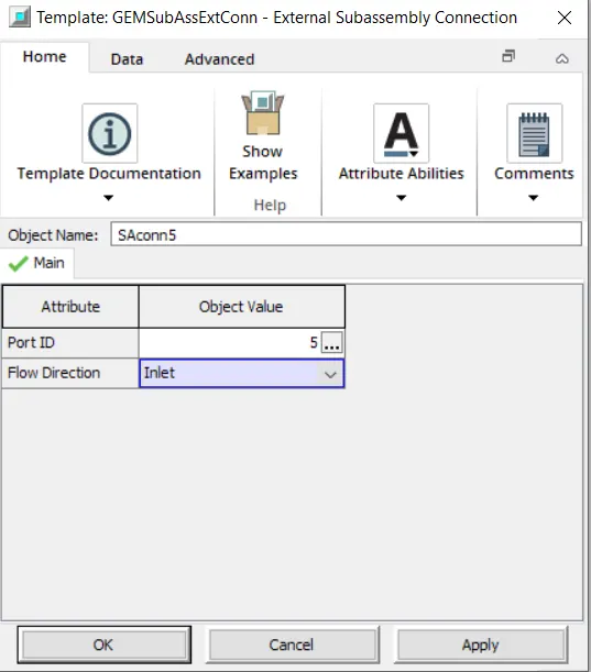
Now for the input, we should add the connection. Go to add connection select port 1 and the connection as "Sub assembly connection" and port i'd is specified as 5 and it is considered as input.
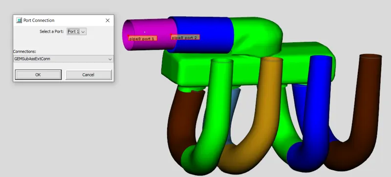
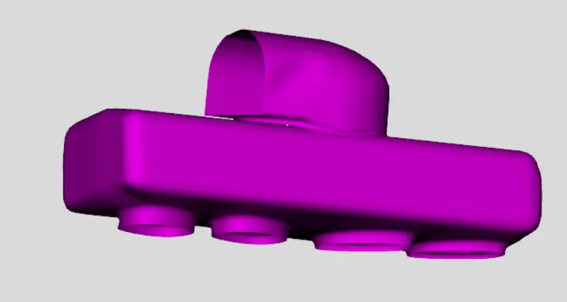
Now the top component is divided by using "3-Points Cutting Plane".
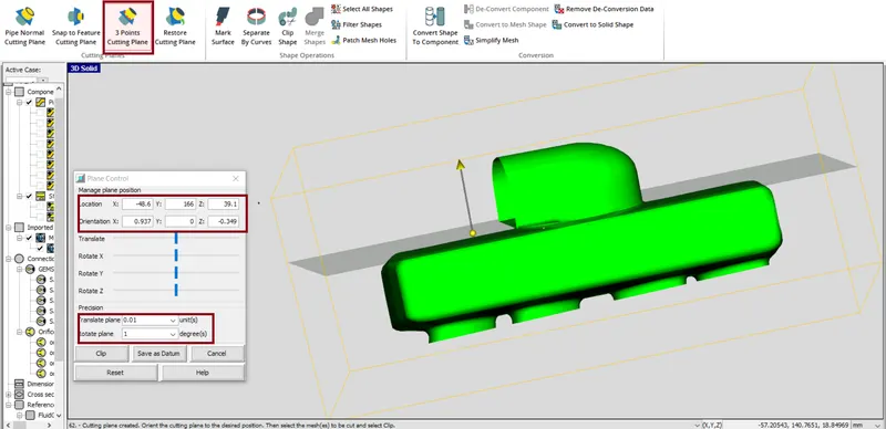
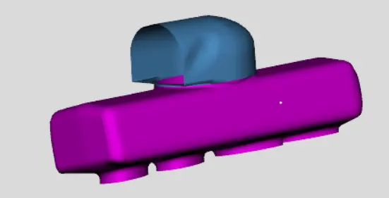
Now we need to convert the top part from shape to component.
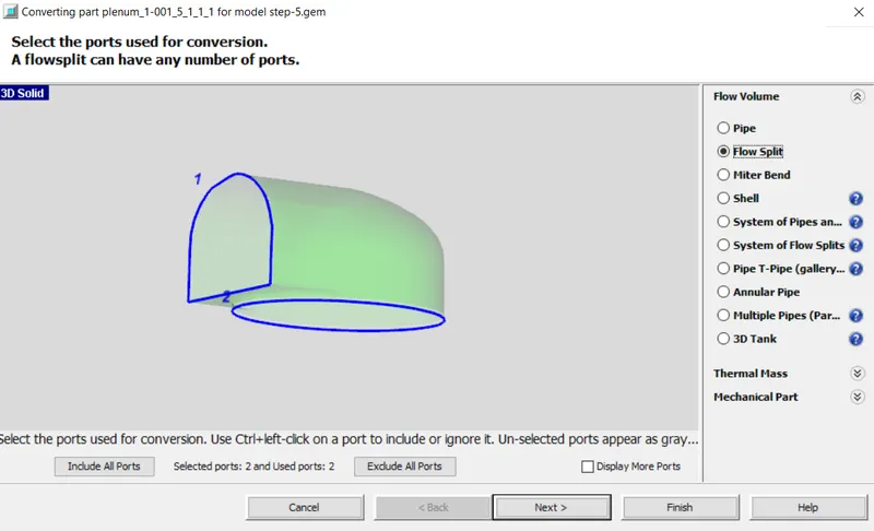
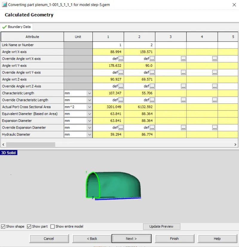
Next, we need to convert the center section into a flowsplit. By using the "3-Points Cutting Plane' and do it for both the sides.
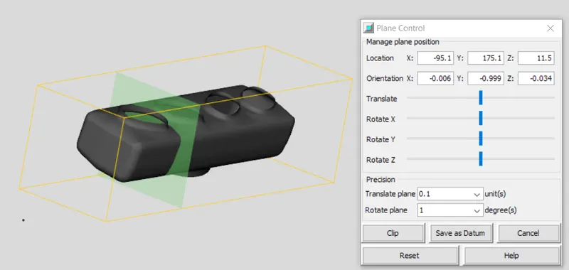
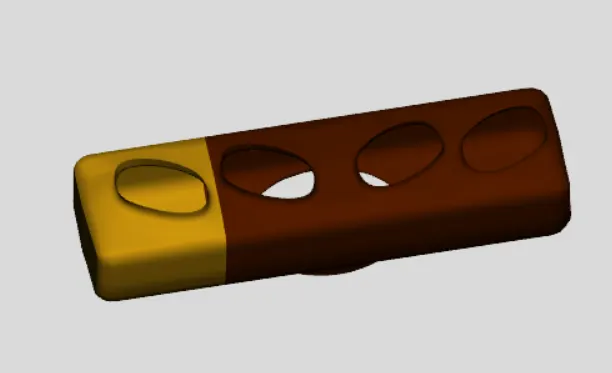
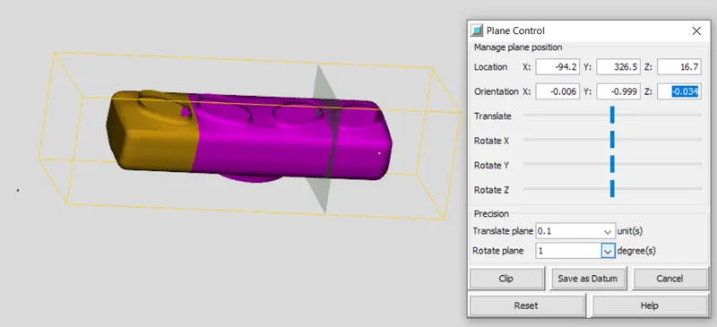
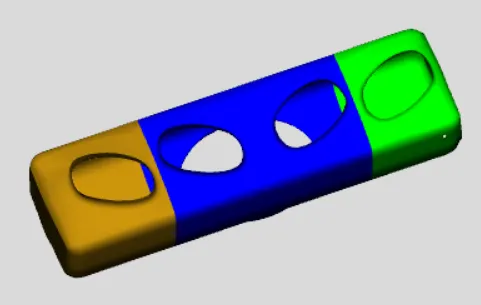
Now the middle mortion cannot be divided because there is a common entry i.e. from same path its going to two runners. Now we have 3 flowsplits, so we should convert shape to component.
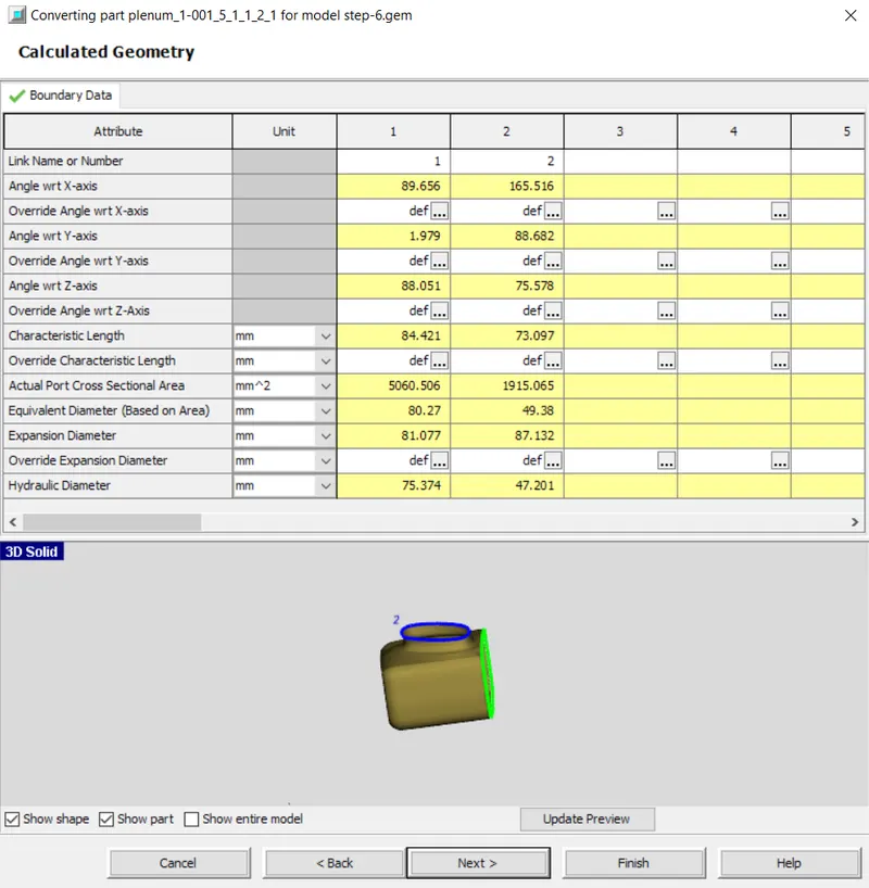
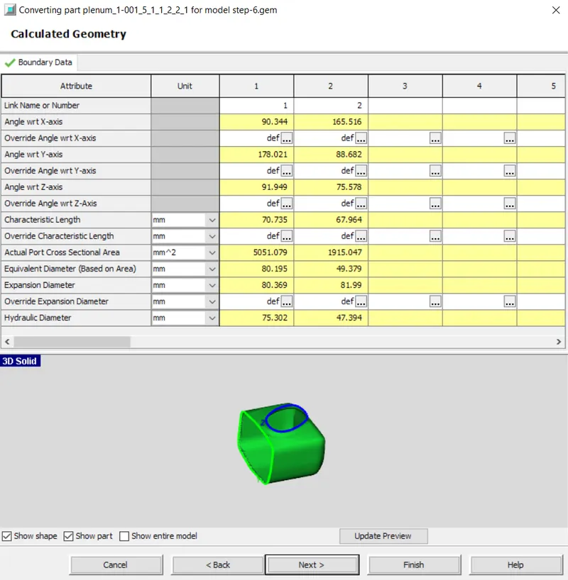
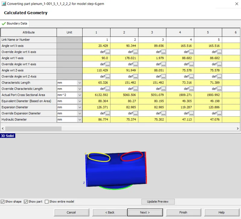
Now expose all the components and check if there are any gaps. We find the gaps between the pipe and the pressure chamber and it should be closed with extruded joints using the connection option. i.e. Flow > Connections > Flow connection. After selecting an option, the possible connections will be displayed. Select them to close the gap.
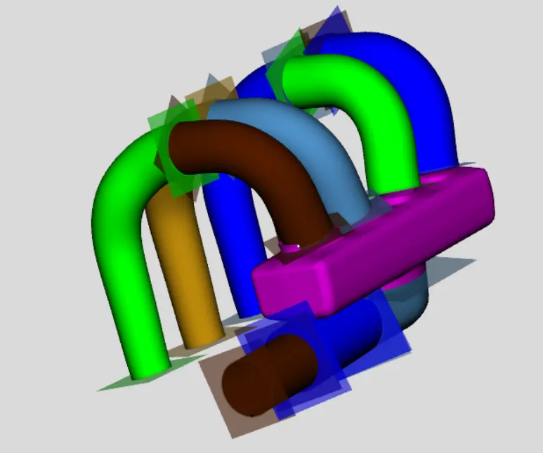
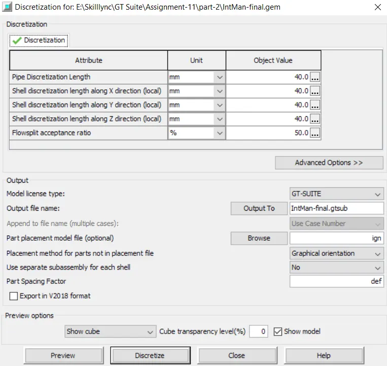
Now we need to discretize the model. Before we discretize the model we should do the orientation and then descretize.
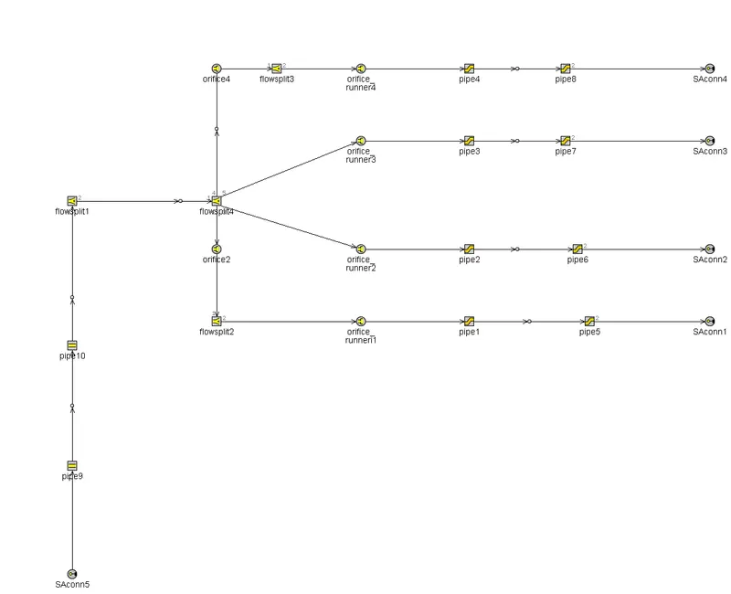
Now the 3D model is converted to 1D model. We need to systematically align connections. So we get the below 1D model as output.
Conclusion:
Therefore, the intake manifold is built from an STL model.