Week 6 - CHT Analysis on a Graphics card
Target:
Perform a steady-state conjugate heat transfer analysis on the graphics card model. You can use suitable materials of your choice for simulation. Make sure you have correctly defined the correct solid and liquid zones.
Run the simulation for the best possible mesh with a combination of coarse and fine mesh in different areas. Explain the reason for choosing a particular network setting.
Objectives:
- Run the simulation by varying the velocity from 1m/sec to 5m/sec for at least 3 velocities and discuss the results.
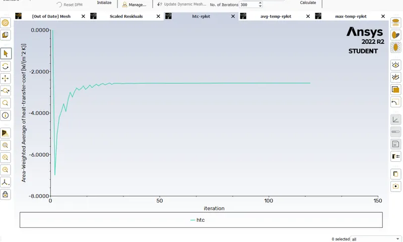
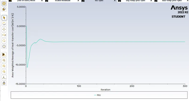
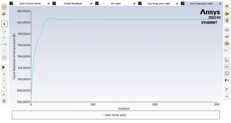
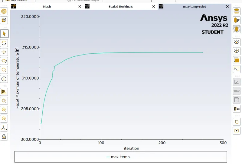
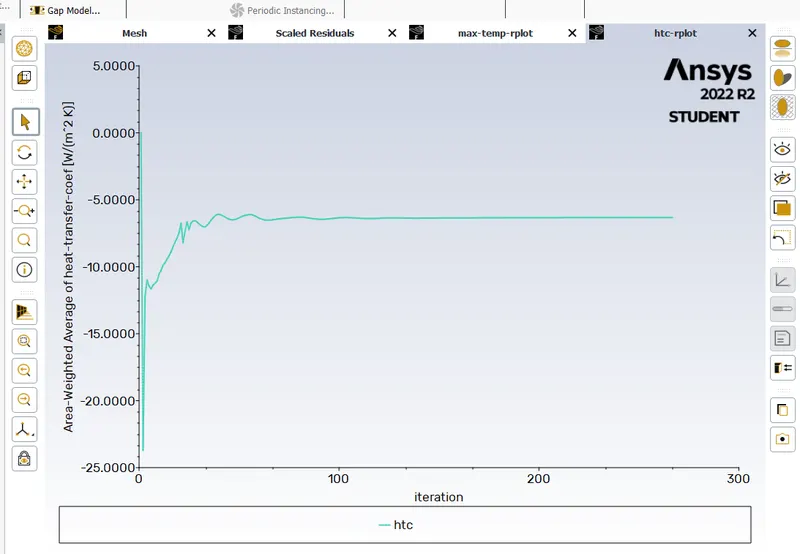
- Finding out the maximum temperature and heat transfer coefficient attained by the processor.
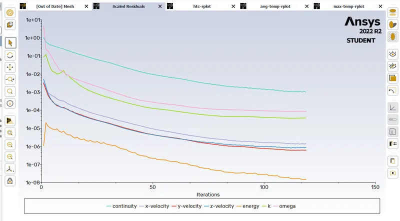
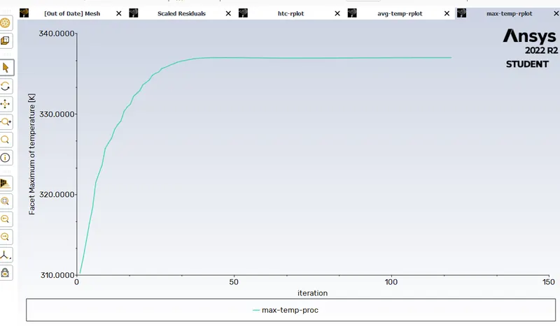
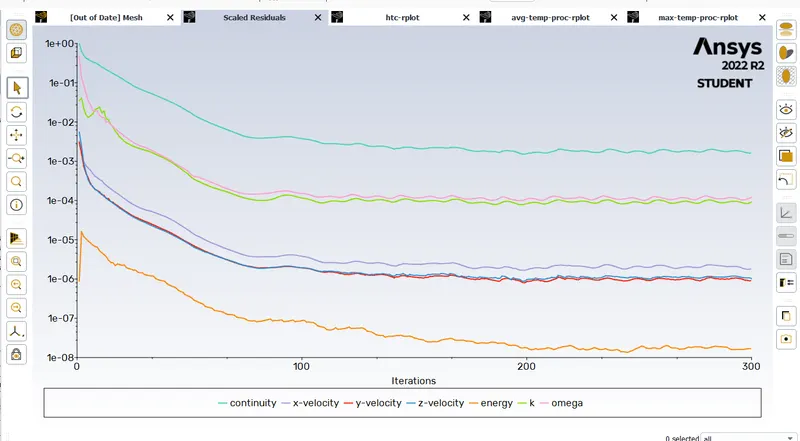
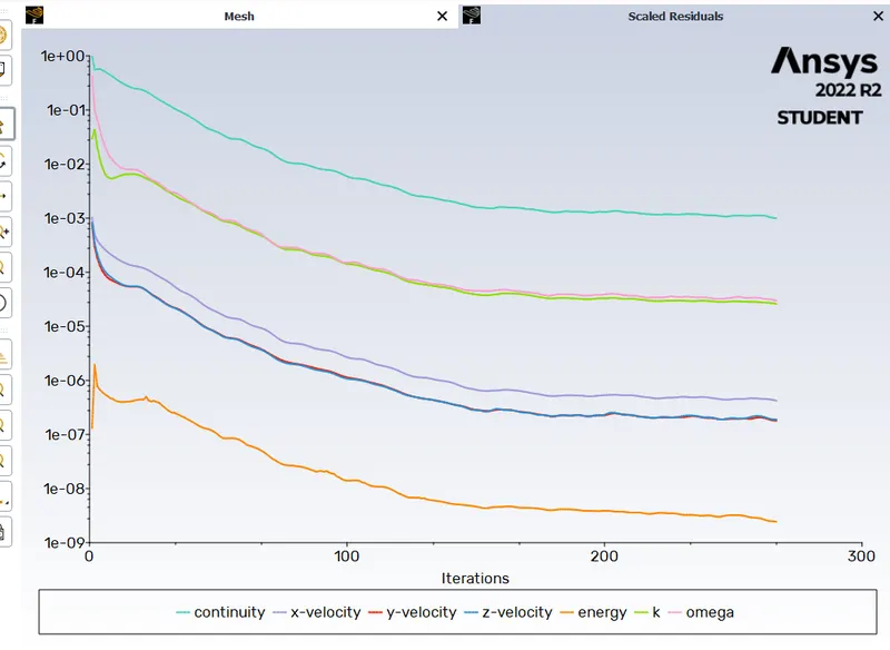
- Proving the simulation has achieved convergence with appropriate images and plots.
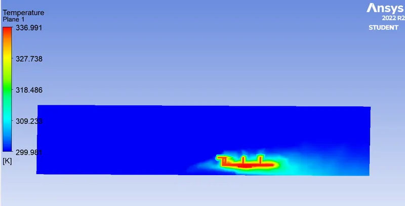
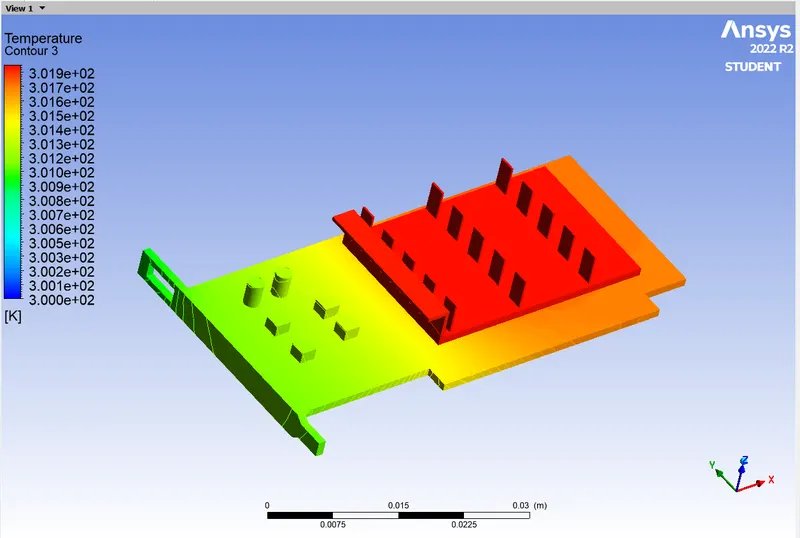
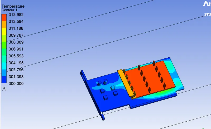
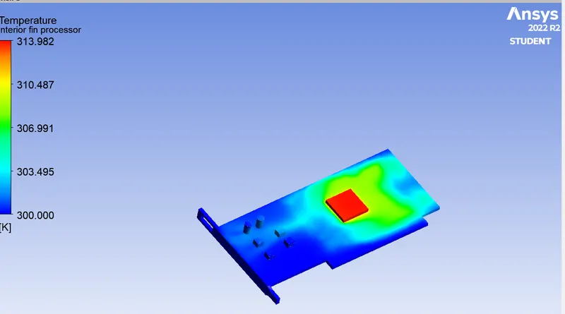
- Identifying potential hotspots on the model.
THEORY:
Conjugate Heat Transfer (CHT) Analysis:
Conjugate heat transfer analysis is used for processes that involve different temperatures involving solids and fluids due to thermal interaction between them. A typical example would be the heating or cooling of a solid by air flow.
The exchange of heat between two bodies is known as heat transfer and the rate of heat transfer is directly proportional to the temperature difference between them. Heat transfer in solids usually occurs by conduction, while in the case of liquids, heat transfer occurs by convection. The efficient combination of heat transfer between solids and liquids is the key to designing efficient coolers, heaters or heat exchangers. Forced convection is the most common way to achieve higher heat transfer rates. In some applications, performance is further improved by combining convection with phase change (for example, liquid water to vapor phase change).
Solid heat transfer and fluid heat transfer are usually combined in most applications. This is because fluid flows around solids or between solid walls, and usually solids are immersed in fluids.
An accurate description of parameters such as material properties, flow regimes, geometry configurations, selection of correct models based on the physics to be captured, heat transfer regimes near boundaries is required for the analysis of temperature fields and heat transfer.
CHT practice problems are used to determine:
- Maximum and minimum temperature in different parts of the system. e.g.: combustion chamber, gas turbines, chemical containers, etc.
- The temperature distribution is related to the thermal stress on a particular wall or system, etc.
- Temperature response in time-dependent applications, such as a heating/cooling problem (for example, in the case of cooling a specific system, such as engine cooling)
- Overall heat transfer coefficient.
Graphic Card or GPU is an electronic component often a computer's pepheral, responsible for computing the graphic signals, later transmitted to a graphic device. It has various range of performance as well as power usage. based on the design, the power rating is often specified on the package, the gpu may have a power rating of over 50W to 2000W. Many system architectures prefer modular gpu's for better power and accordingly heat management.
Study overview:
To achieve the goal, a simulation of conjugate heat transfer was performed. Since the study is computational in nature, mesh refinement is a mandatory task. Network refinement strategies and studies were discussed in the next section. After mesh refinement, the study was followed in two cases as discussed below.
Case 1:
An inlet velocity of 1 m/s is to be applied to the inlet boundary.
Since the velocity is the lowest of all cases, less cooling is expected in this case. In this case, the heat transfer coefficient and the maximum temperature need to be calculated.
Case 2:
An inlet velocity of 3 m/s is to be applied to the inlet boundary.
As the speed increases further, the best performance of all three cases is expected. Also, an increase in velocity will lead to a turbulent effect that can drastically affect heat transfer.
Case 3:
An inlet velocity of 5 m/s is to be applied to the inlet boundary.
In this case, the best performance is expected.
Geometry and Assumptions:
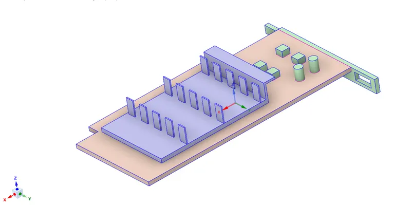
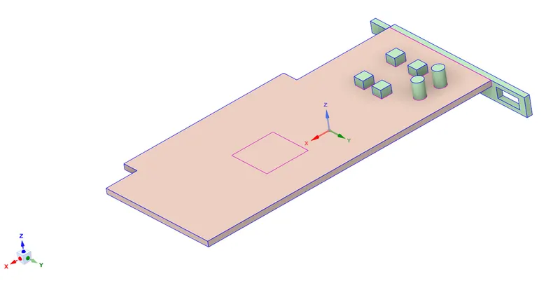
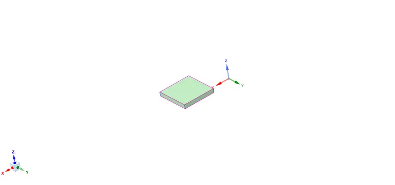
The geometry considered for this study is a simplified graphics card model. The entire card can be divided into three main areas:
1) card base
2) processor
3) fins
- here we have used base board material as polystyrene which has
- Resistance to bacterial growth
- Resistance to moisture
- Lightweight
- Provides insulation
- Durable
- Recyclable
2.And for processor we have used material as silicon. Silicon compounds have a wide variety of useful properties, mostly because they can bind other atoms very tightly, and in complex arrangements. Various silicates, like calcium silicate, are a primary component of Portland cement, the main binder in concrete, mortar, and even stucco. Some silicate-rich materials can be heated to produce hardened ceramics like porcelain, while others will fuse to form the world’s primary form of glass, soda-lime glass. And silicon can also be useful as a trace additive in other substances, like cast iron, which uses both carbon and silicon to make iron more resilient and less brittle.
3. For fins i have used material as aluminium
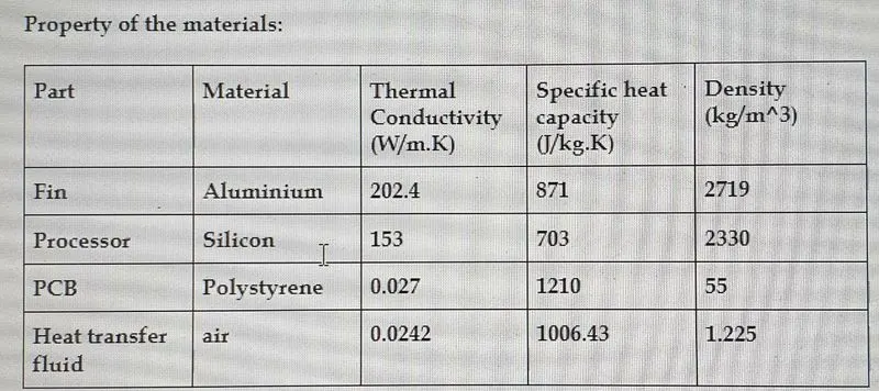
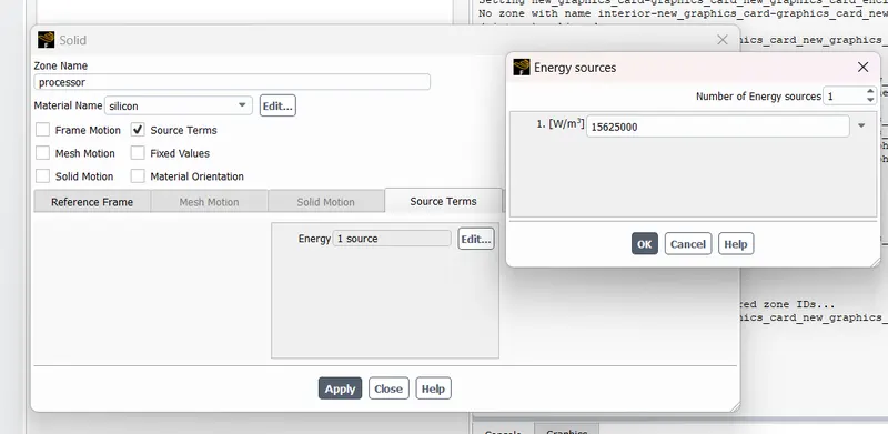
Here we will see the new term volumetric heat source. volumetric heat source is the energy released in a unit of volume per unit of second. the energy released from the processor is the power consumed by the processor, i.e. the energy released from the processor is 1w. the dimensions of the processor are 8*8*1 mm^3 and the length of the graphics card is 56 mm
so the final volumetric heat source is 1/(8*8*1) W/mm^3 = 15625000 W/m^3.
The working fluid that flows in the housing for cooling the card is standard air from the Fluent database. The thermodynamic and physical properties of these materials will be discussed in detail in the Case Setup section.
To solve the conjugate heat transfer problem, we use the sharing tool in the Ansys SpaceClaim toolbox to be able to generate a conformal mesh. The entire geometry and its components discussed above are shown in the following figures
Graphics Card:
Base of the card:
Processor:
Fins:
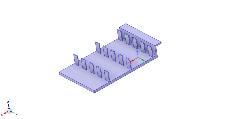
Note: Enable the SHARE TOPOLOGY
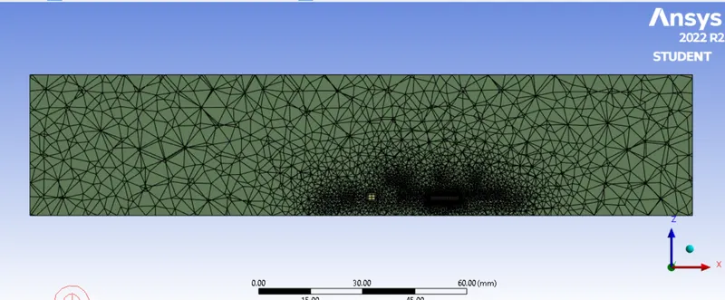
Mesh refinement:
In this study, heat transfer from the heat generating Unit (Processor) will get dissipated by 2 methods, conduction via fins and base plate and convection by air.
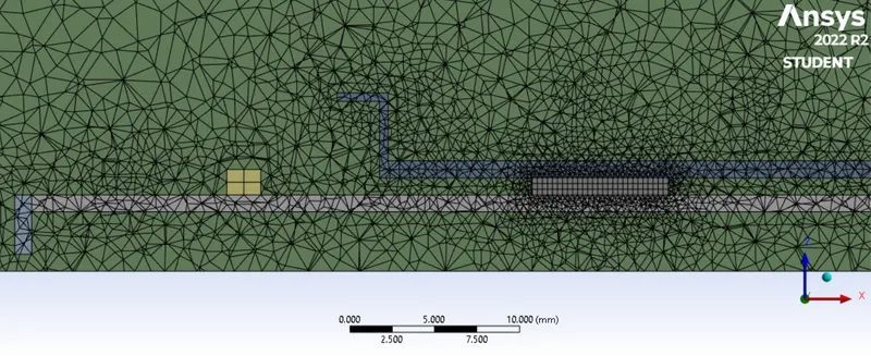
The geometries carrying the heat away from the processor are fins, base plate and vicinity fluid in these two media combined with fluid in contact with processor. Mesh refinement has been approached by changing the body sizing of these geometries.
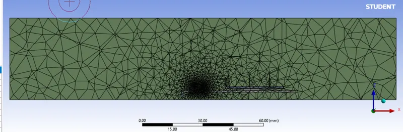
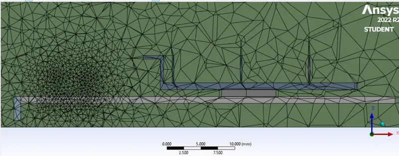
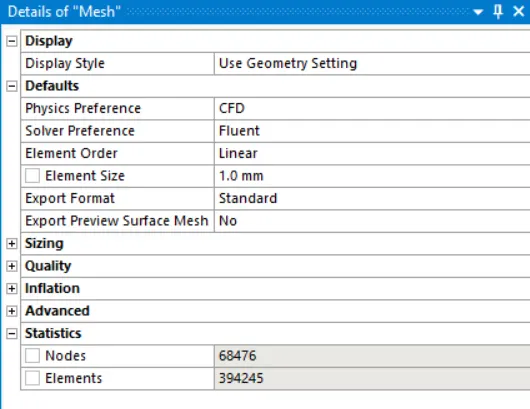
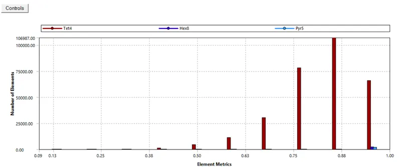
First simulation is taken for base mesh and no changes are made in base mesh. But for the 3rd simulation the mesh is refined and body sizing is implemented for parts of geometry
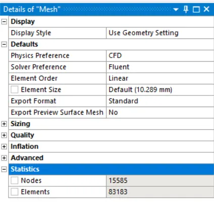
BASE MESH:
Quality:
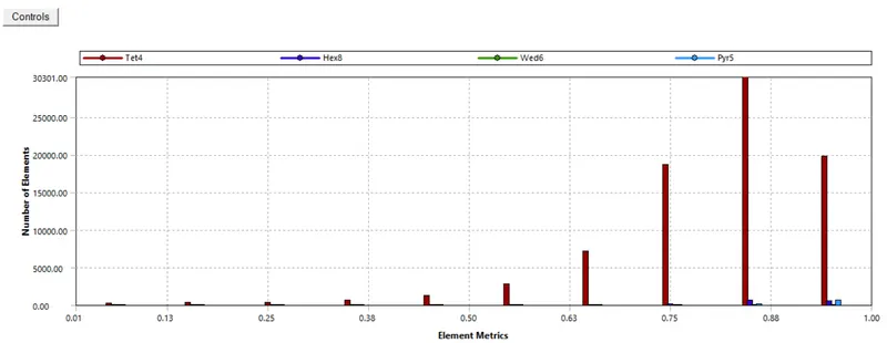
Element no:
SET UP:
- set up physics
- check energy equation
- select k omega turbulent model
- create materials both solid and fluid
- air for fluid
- aluminium, polystrene and silicon for solid
- add materials for cell zone
- create boundary layers and add shell conduction
- giving inlet velocity as per cases
- select materials for wall
- between solid and fluid material will be of solid
- between 2 solids it will be of the solid which has no source
- add source for processor wall ie., 15625000wm3
- initialize
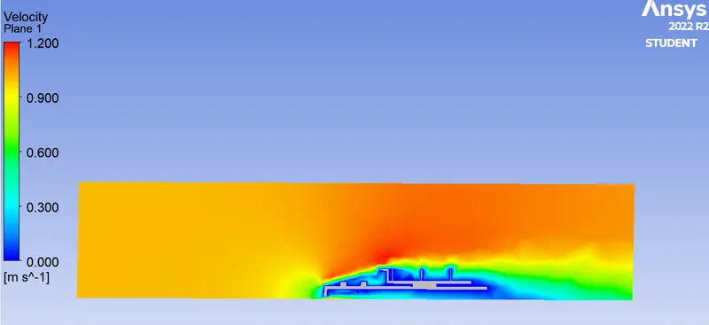
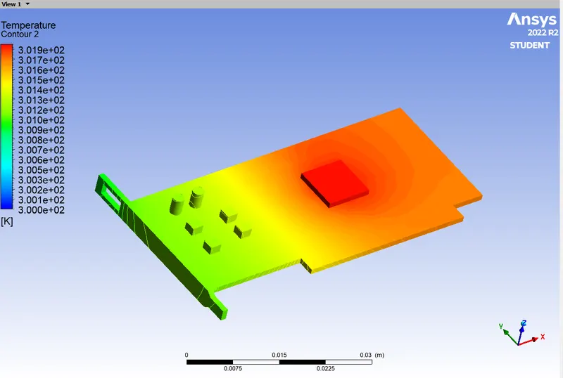
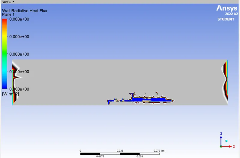
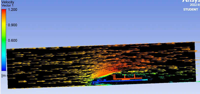
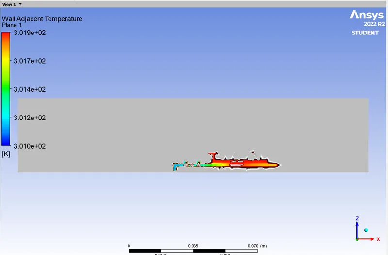
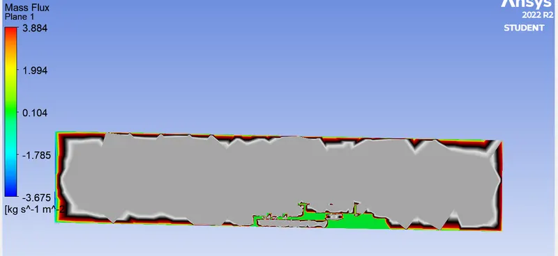
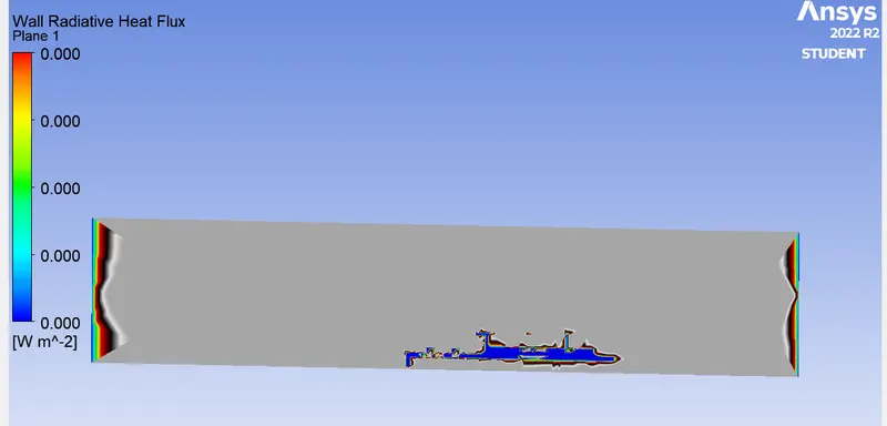
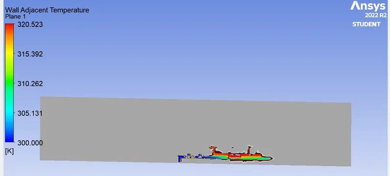
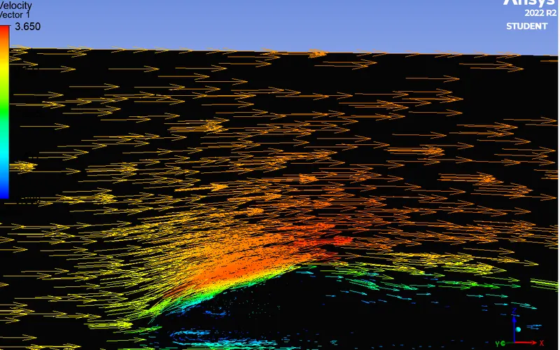
- create plane on zx axis and make 2 contour of temperature and velocity
- create a point on processor for creating a vertex average temperature and note co-ordinate for other simulation
- start simulation and compare results for different simulation
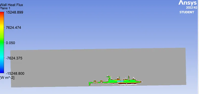
Case 1: 1 m/s
Case 2: 3m/s
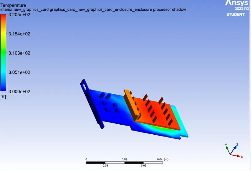
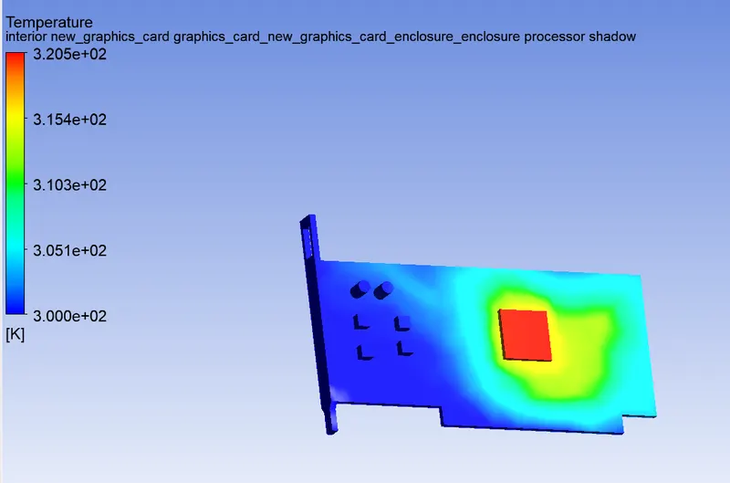
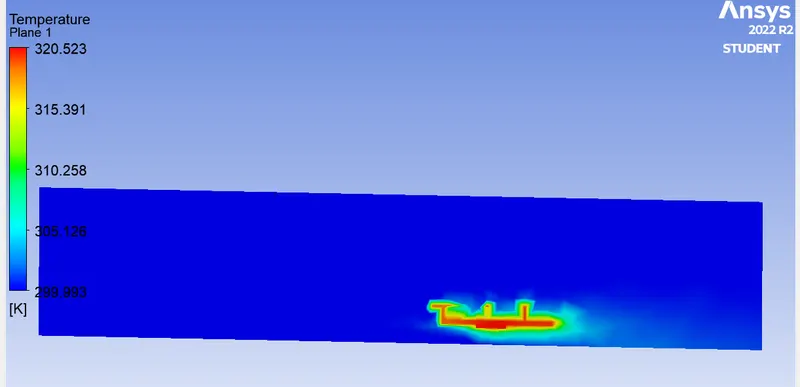
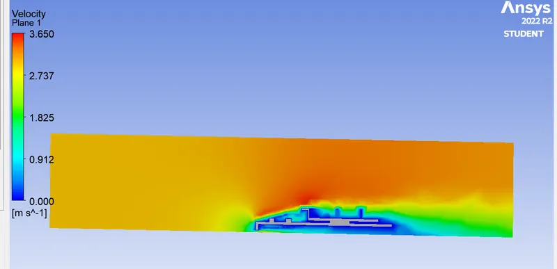
REFINED MESH:
case 3: 5 m/s
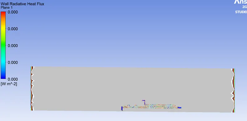
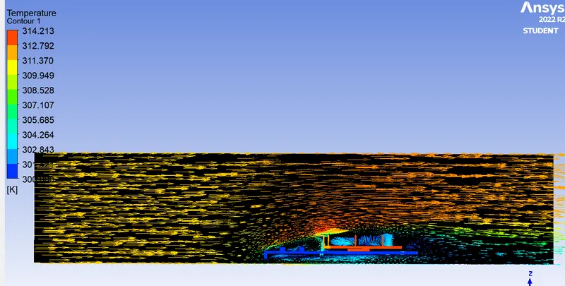
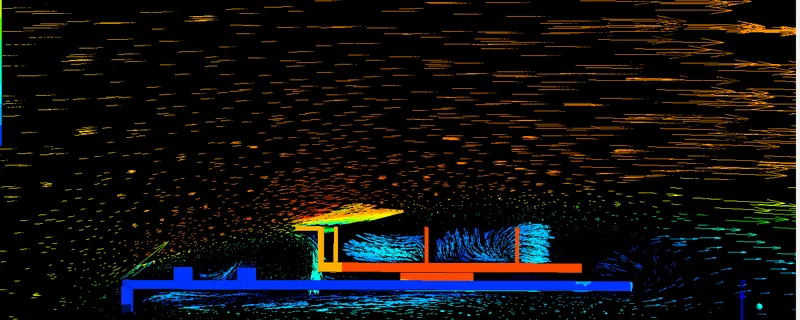
Conclusion:
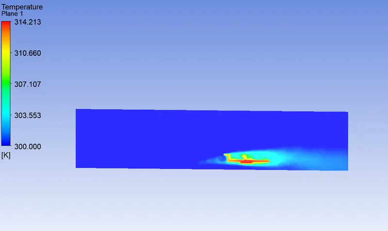
we can se the maximum temperature and heat transfer coefficients according to the 3 cases
case 1 for velocity 1m/s

case 2 for velocity 3m/s
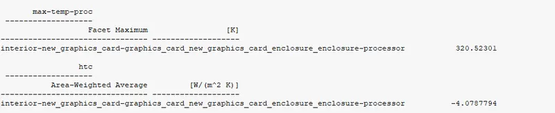
case 3 for velocity 5m/s with refiend mesh

- As the velocity decreases, we observe that the thermal hot-spots are much stronger in magnitude and have an impact on larger regions of the graphic car. This observation is inline with the theoritical expectation of the effects of the convective heat transfer.
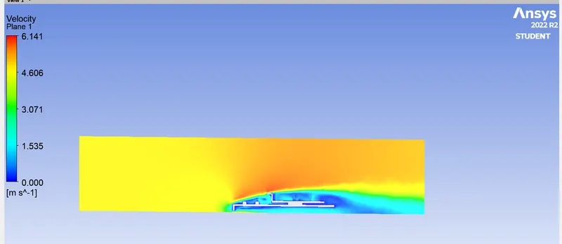
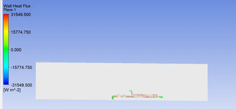
- The heat transfer coefficient near the fins is highest for inlet velocity of 5m/s. This observation is inline with the experimental trend.
- A higher velocity in a certain region means a higher Reynolds number. This is the reason why the heat transfer coefficient is the highest in this region, which means that the maximum heat transfer from the fluid to the solid occurs in this region. This also results in a higher temperature of the solids at that location.
- The heat transfer coefficient is a function of the fluid properties at film temperature, temperature difference, temperature coefficient, buoyancy, and so on, so the resolution of the mesh at the walls usually has the greatest effect on the numerical results.
- For turbulent models, we have to take care of the assumptions and boundary conditions that you enter into the program. The mesh is a very important parameter to get nice results, so we need to refine it in an important place of our drawing.
- Some factors to consider, the most important of which is the turbulent boundary layer. If we are using any kind of low Reynolds turbulence model we are considering an improved wall treatment (like your K-w SST model) we need to make sure we stay in the laminar sublayer region where the velocity profiles are assumed to be laminar and viscous stress. dominates the wall shear, which means
- mesh dependency test is very important to get reliable results.