Week 10 - Simulating Combustion of Natural Gas.
Problem Statement:
Perform the heat transfer analysis using ANSYS-Fluent software for the cylindrical
Lithium ion Battery with heat generation boundary condition. Create an enclosure and
use air as the working fluid for cooling the battery back system (4 x 2). Take air inlet
temperature as 26°C and space between the batteries as 2 mm.
Property of the Lithium-ion Battery
Nominal Voltage = 3.6 V
Nominal capacity = 2.2 A
Density = 2722 kg/m3
Specific heat = 1200 J/kg.K
Thermal Conductivity = 37.6 W/m.K
Heat Source = 48750 W/m3 (1.5 C discharge rate)
Size of the Battery = 18 mm diameter and 65 mm height.
Expected results:
• Explain why battery cooling is needed. And give a brief description about various
techniques for battery cooling.
• Perform Mesh independent study for any one case and based on your judgment
use the more suitable model for further cases.
• Run the simulation by varying the velocity of air as 3, 5 and 10m/sec and discuss
the results.
• Find out the maximum temperature and heat transfer coefficient obtained by the
battery.
• Based on the results and on your judgment, select one case (3, 5 or 10 m/s) and
vary the space between the batteries as 2, 4 and 6 mm, then discuss the results.
• Prove that the simulation has achieved convergence with appropriate images and
plots (Velocity and temperature contour plots on the cut planes).
• Create the animation to observe the temperature distribution and velocity vector.
• Summarize the results in tabulation/ graphical form.
• State the inferences based on the results
AIM:
Perform the heat transfer analysis using ANSYS-Fluent software for the cylindrical 4 by 2 Lithium-ion Battery with heat generation boundary conditions and study the battery thermal management system(BTMS).
OBJECTIVES:
- Do an independent network study for any single case (for speed) and use a more appropriate model for other options.
- The simulation is carried out by changing the air speed to 3, 5 and 10 m/s and discussing the results.
- Determination of maximum temperature and heat transfer coefficient obtained by
battery. - Based on the results and your judgment, choose one case (3, 5 or 10 m/s) and change the distance between the batteries to 2, 4 and 6 mm, then discuss the results.
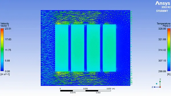
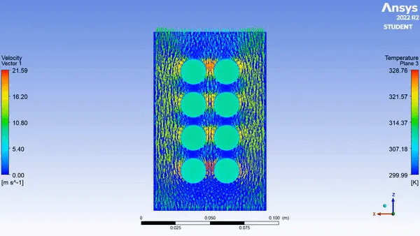
- Create an animation to observe the temperature distribution and the velocity vector.
- Summarize the results in tabular/graphical form. Identify potential hotspots on the model. State the conclusions based on the results
THEORY OF BATTERY THERMAL MANAGEMENT SYSTEM(BTMS):
The battery unit is an integral part of the electric vehicle system. Battery units store the electricity required to drive an electric vehicle and the battery's power capacity is measured in kW. But there are some challenges related to batteries and their operation,
- High cost
- Long charging time
- Overheating
- Protection against short circuits
The last 3 issues can be mitigated if the temperature range of operation is managed under control. It will also prevent thermal runaway propagation.
Battery Thermal Management System (BTMS) is a design approach to cooling technologies. Before studying BTMS, we should know the application and main use of battery management systems.
As we know, conventional vehicles use gasoline and diesel, which actually cause environmental pollution and energy shortage, which are two major problems facing the world. Considering the above situation, we have come up with electric vehicles, where the main source of power for the vehicle depends on the battery. The electric vehicle market consists of different types of batteries such as lead-acid, nickel-cadmium, lithium-ion, plastic lithium, etc., and their energy sources are listed below.
By comparing to all other batteries Lithium-Ion battery has a good energy density of around 350Whr/L(in terms of size) or 200Whr/kg(in terms of weight).
PRINCIPLE OF LITHIUM-ION BATTERY
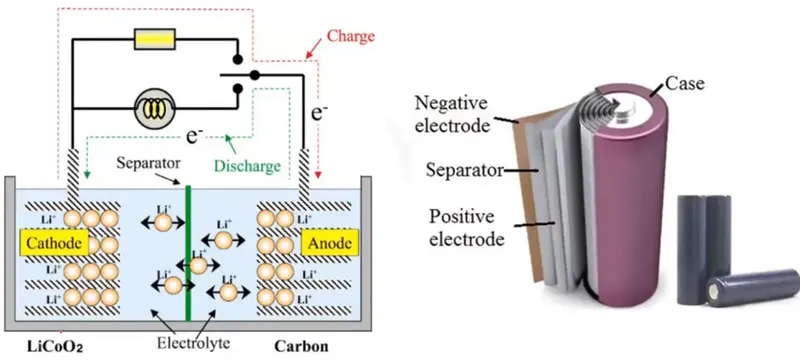
The construction of lithium-ion batteries consists of a positive (cathode) and a negative (anode) electrode. Here, the cathode consists of lithium-ion base (LiCoO2) and the anode consists of graphite (carbon). A thin plastic membrane called a separator separates the cathode and anode. The entire setup above is embedded in an electrolyte called lithium salt based electrolyte. The principle of operation is that ions are exchanged between the cathode and the anode during the charge or discharge movement of electrons in the external circuit. During charging, the choices move from cathode to anode similarly during discharge, electrons move from anode to cathode through external circuits. Battery comes in different shapes like cylinder, circle etc.
Battery Thermal Management System (BTMS)
The battery temperature changes due to internal heat during the charging and discharging process.
Uneven temperature distribution causes thermal non-uniformity, which reduces the life cycle and performance of the cell. Increases the chance of battery drain.
The BTMS is required to maintain an even temperature distribution throughout the battery pack. BTMS maintains an optimal temperature range and plays a vital role in the performance and longevity of batteries.
Types of cooling systems
Battery cooling systems can be primarily divided into 3 different types based on the medium used.
- Liquid cooling
- Air cooling
- Phase Change Material (PCM)
- Liquid cooling
Liquids have a higher heat capacity and density compared to gases. This results in a higher rate of heat removal by convection.
Liquid cooling systems are more compact and have lower energy consumption compared to air cooling systems,
Produces less noise
However, there is always the possibility of leakage when working with liquid cooling systems.
Liquid cooling can be done in two ways, direct cooling and indirect cooling.
With direct cooling, the entire surface area of the cell is covered and a uniform temperature is maintained. Removes all hotspots and extends battery life. It is mainly used in data center servers. Due to the risk of a short circuit, this metho is not used for electric cars.
Indirect cooling aims to prevent electrical conduction inside the cells while maintaining high thermal diffusion. In this method, cold plates, water jackets and heat pipes are used to efficiently dissipate heat. All coolant connections are routed outside to eliminate the risk of leakage. This method is used by car manufacturers such as General Motors andTesla.
- Air cooling
Air is mainly used as a cooling medium due to its easy availability and low maintenance costs.
Cooling is done either by natural convection (passive cooling) or forced convection (active cooling). Passive cooling is only suitable for low-density batteries, and typically blowers or fans are used to increase the rate of heat transfer by convection. Batteries near the outlet will show higher temperatures compared to batteries near the inlet. Therefore, care must be taken when designing the battery layout. The flow rate and turbulence of the air stream should be selected to ensure uniform cooling. This type of cooling is used by car manufacturers such as Honda, Nissan and Toyota.
- Phase Change Material (PCM)
Due to its high latent heat, PCM absorbs heat significantly more than conventional materials.
A material with a phase change from solid to liquid is placed next to the cells.
Paraffin mixed with graphite flakes has a melting point of 32 to 38 degrees Celsius, making it suitable for electric vehicles.
Graphite flakes are used to increase thermal conductivity. It also acts as a semi-matrix block that will contain paraffin.
The PCM acts as a shield in the event that one cell undergoes thermal runaway.
Difference between the cell, module, and pack
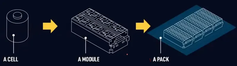
CELL: A single-cell unitary device that converts chemical energy into electrical energy.
MODULE: A module is a set of cells connected in series or parallel. The application of the modules is in two-wheeled vehicles.
PACKAGE: A package is a series of individual modules and protection systems arranged in a shape that will be installed in vehicles. We use packaging systems for heavy vehicle applications.
Types of connections in battery pack/module system
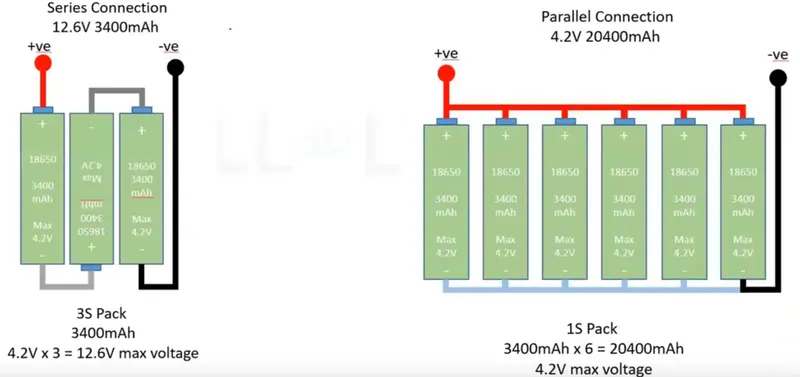
SERIES: Each battery has milliamp-hour and volt specifications, here each battery is 4.2V and 3200mAh, so most applications are 12V. Therefore the 4.2V is not enough to increase the voltage we connect in series (we can multiply the voltage so we get 12V but I can discharge 3400mampH per hour) which is the positive side at the other end and the negative side at the other end of the battery as shown in the picture above. Similarly in PARALLEL connection, if we want to increase the rated power of the amplifier which is 3400 mAh, the rated current is very small, to increase the current flow, then we have to connect the batteries in parallel, which is 3400 mAh multiplied by 6 is 20,400 mAh with a maximum voltage of 4.2V .
C-rating is a unit that declares a current value that is used to estimate or determine the expected sufficient time of a battery under variable charging or discharging conditions. As the C rating increases, the battery's heat generation due to electron flow from charging or discharging the battery increases.
MODELING APPROACH:
- A battery system with 8 batteries (4x2) is considered for this study.
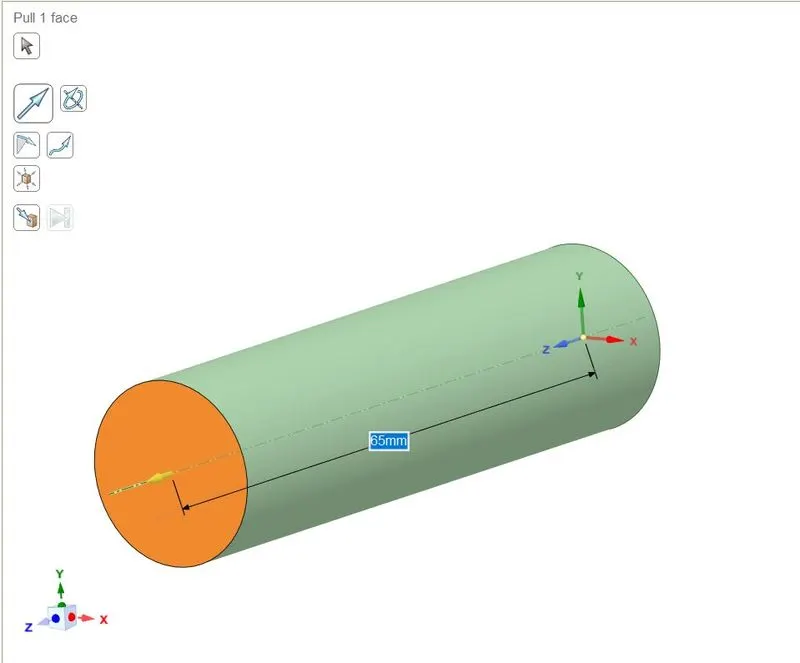
- Battery size = diameter 18 mm and height 65 mm.
- A closed space is created and air is chosen as the working medium.
- The heat generation at the battery is taken and a heat generation boundary condition is assigned.
- The standard K omega turbulence model is used because the flow is turbulent.
- The material for the battery is chosen as Lithium
GEOMETRY USING SPACECLAIM
- Initially, we draw the circles this is equally placed based on the spacing(2,6,8) provided but here we are considering 2mm and the diameter of the circle to be 18mm.
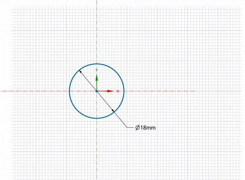
- Use the Pull tool, extend the circle in the z-direction by 65mm to get a round cylinder.
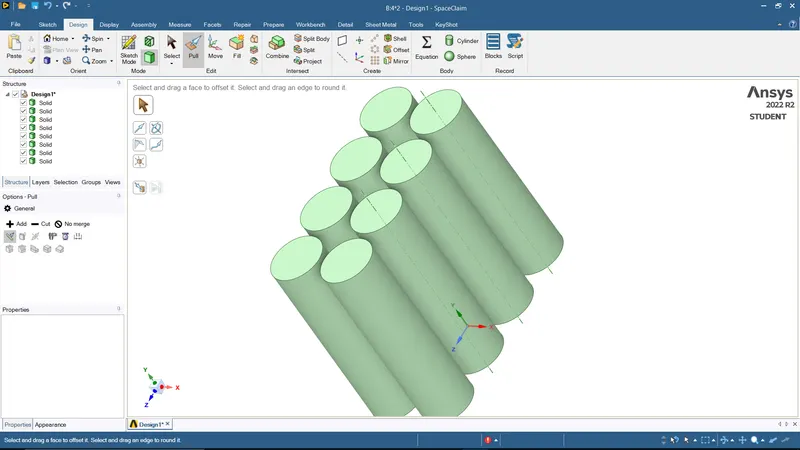
- Use the pattern option under the Design tab to create a 4x2 battery layout.
- I selected all the circles once the sketching is done and use the pull option to extrude them into the cylinder with a length of 65mm as shown picture below.
- I Created the enclosure around the battery module for performing the analysis.
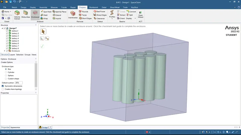
- use the share topology option for nodal information exchange and disable the preserve instance.
MESH
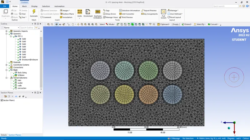
We will dimension the mesh option=> insert=>size ways (specify the appropriate mesh size) similarly for the enclosure volume around the battery, we will dimension the mesh option=> insert=>size methods (specify the appropriate mesh size).
Creation of INFLATION LAYERS
Before creating the inflatable layers, we need to select a name that is for the inlet, outlet, convection wall and battery wall.
We create the inflation under network options=> inflation=>select all surfaces in the selected name selection option=>under name selection=>battery wall=> inflation option=>thickness of the first layer (0.3m)=>under layer number(6)= >select update network.
SETUP AND SOLUTION
- In this, we provide fundamental physics, types of solvers, boundary conditions, and the kind of turbulent model used.
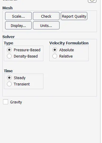
- Initially, we go for the SOLVER option here we are the type of solver used is PRESSURE BASED SOLVER (M<0.3), and since the variable is not varying with respect to time select the STEADY STATE option.
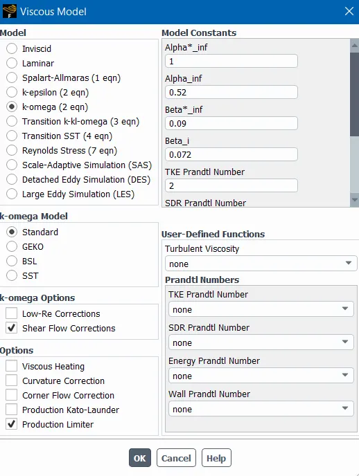
- In the following step for the PHYSICS, the window selects the VISCOUS option we get the window opened up. Here we are selecting the type of viscous model, a TURBULENT model (k-omega standard). Since we have to calculate the temperature energy is turned on.
- Here for solids materials aluminum, Lithium this assigned under the solids sections there are properties are stated below.
- Density = 2722 kg/m3
Specific heat = 1200 J/kg.K
Thermal Conductivity = 37.6 W/m.K
Heat Source = 48750 W/m3
LITHIUM thermal conductivity(k=37.6 W/mK) specific heat capacity(cp=1200 J/kg K) density(rho=2722kg/m3)
- For the battery, assigning lithium in cell zone condition.
- In the cell, zone conditions check whether all materials are assigned appropriately. For heat generation under the battery, I give the heat source term 48750 W/m3
- We are giving the BOUNDARY conditions for the inlet velocity as 3m/s, 5m/s, 10m/s, and the default temperature as 300K.
- The hybrid method is used for initialization.
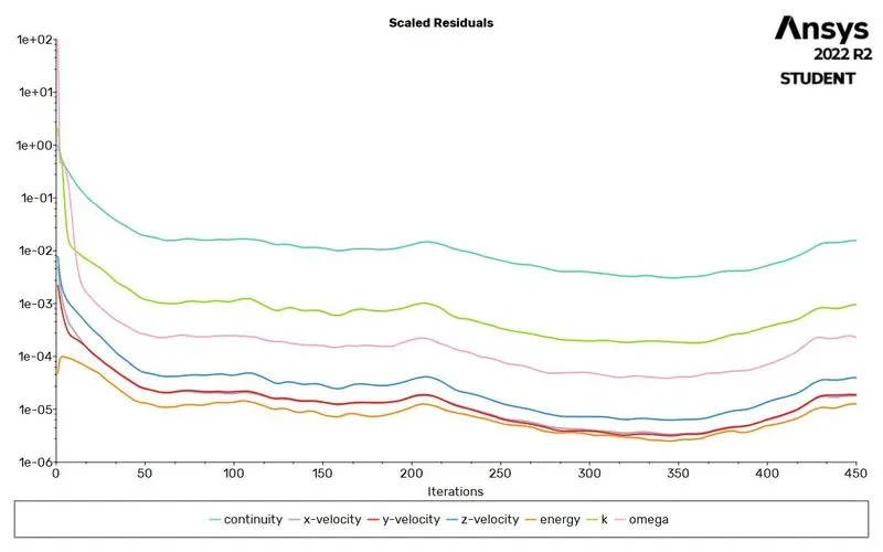
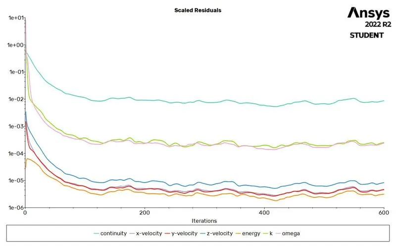
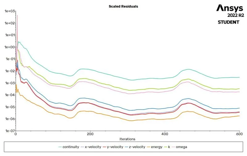
- Run this simulation based on solution convergence hence here this simulation converges.
- Finally, getting the graph heat transfer coefficient for the processor, temperature of the processor, and contour plots.
RESULTS
STUDY 1:
MESH INDEPENDENCE STUDY(STEADY STATE ANALYSIS)
MESH SIZE: 8mm external enclosure for a velocity of 3m/s
CONVERGENCE
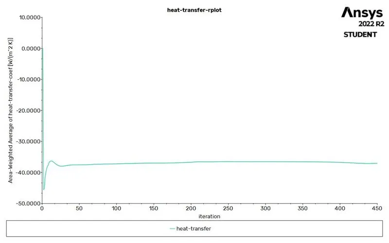
HEAT TRANSFER COEFFICIENT PLOT
TEMPERATURE PLOT
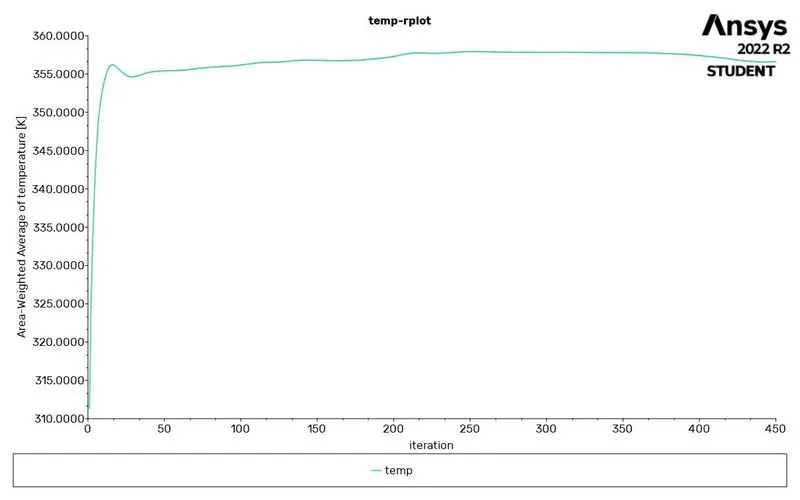
The average temperature of the battery is 356K
The average heat transfer coefficient is -37.05W/m^2K
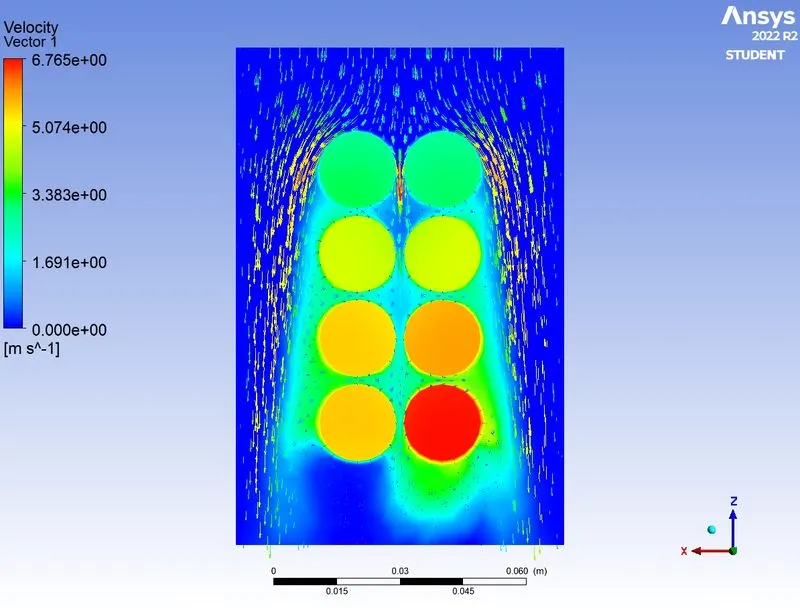
TEMPERATURE CONTOURS
STUDY 2:
SIMULATION FOR FORCED CONVECTION WITH VELOCITY OF 3, 5, and 10m/s(SPACE BETWEEN BATTERIES IS 2mm-STEADY STATE ANALYSIS)
CASE 1: For 3m/s
CONVERGENCE
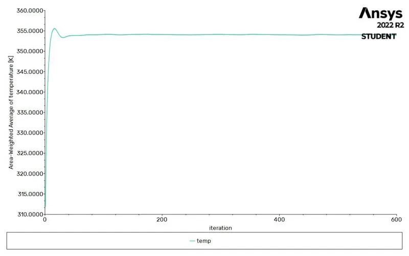
TEMPERATURE PLOT
HEAT TRANSFER COEFFICIENT PLOT
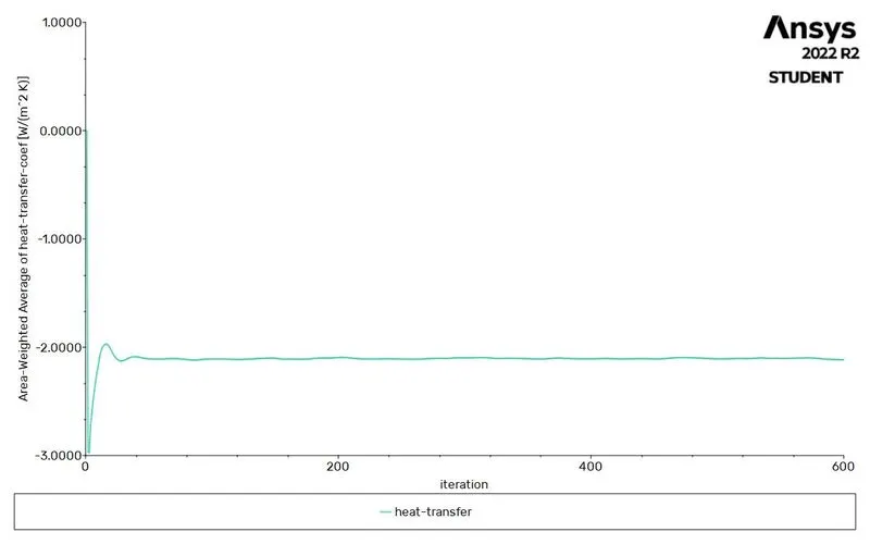
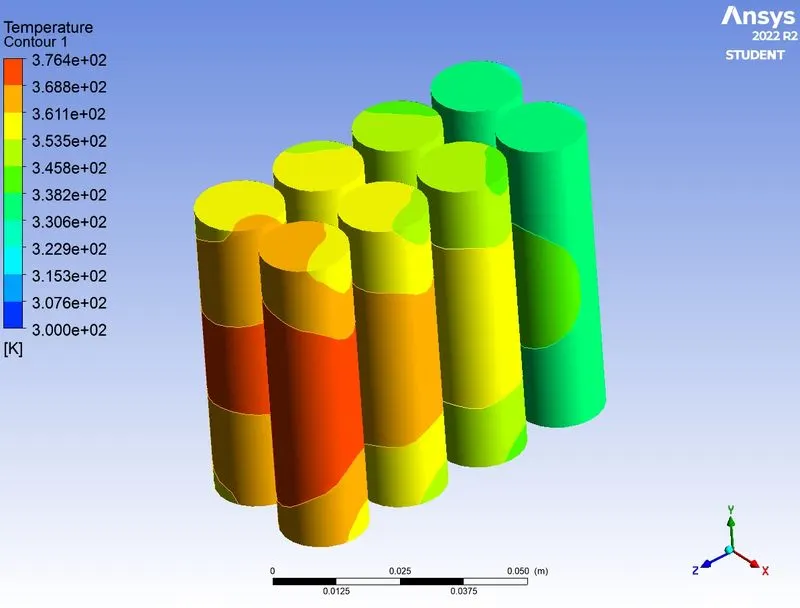
The average temperature of the battery is 353K
The average heat transfer coefficient is -33.45W/m^2K
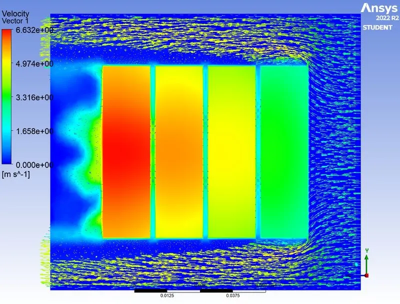
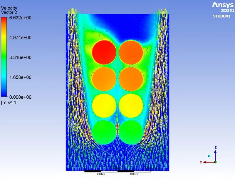
TEMPERATURE CONTOURS
CASE 2: For 5m/s
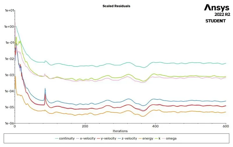
CONVERGENCE
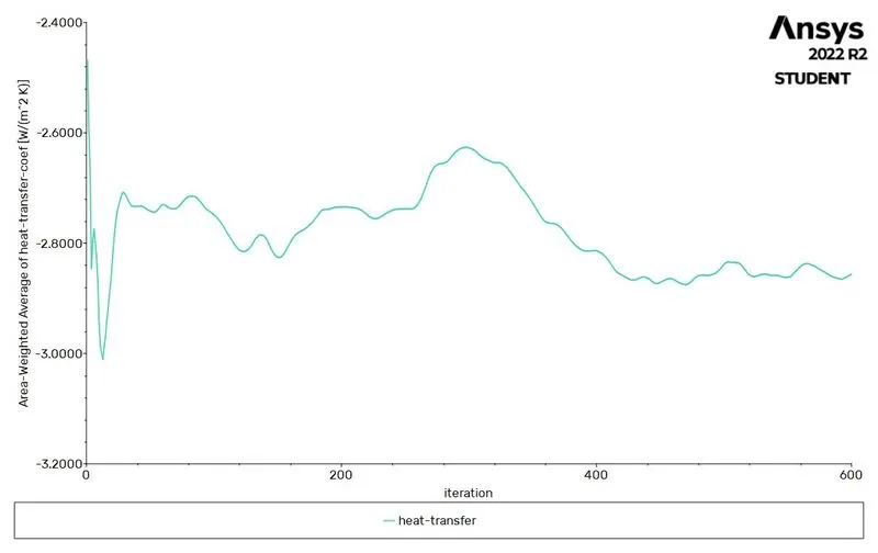
HEAT TRANSFER COEFFICIENT PLOT
TEMPERATURE PLOT
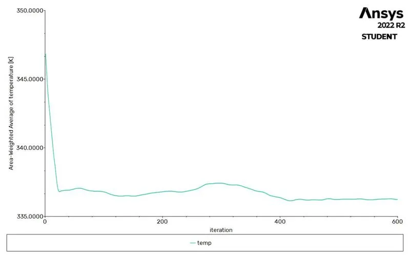
The average temperature of the battery is 336.23K
The average heat transfer coefficient is -51.25W/m^2K
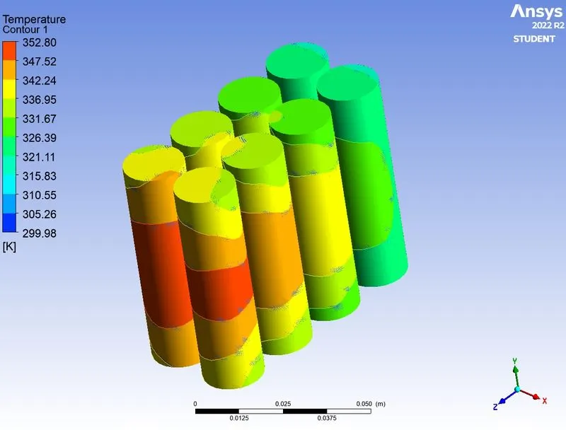
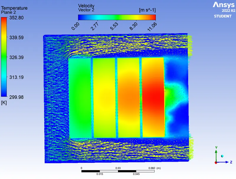
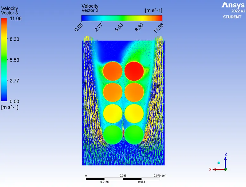
TEMPERATURE CONTOURS
CASE 3: For 10m/s
CONVERGENCE
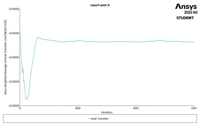
HEAT TRANSFER COEFFICIENT PLOT
TEMPERATURE PLOT
CASE 3: For 10m/s
CONVERGENCE
HEAT TRANSFER COEFFICIENT PLOT
TEMPERATURE PLOT
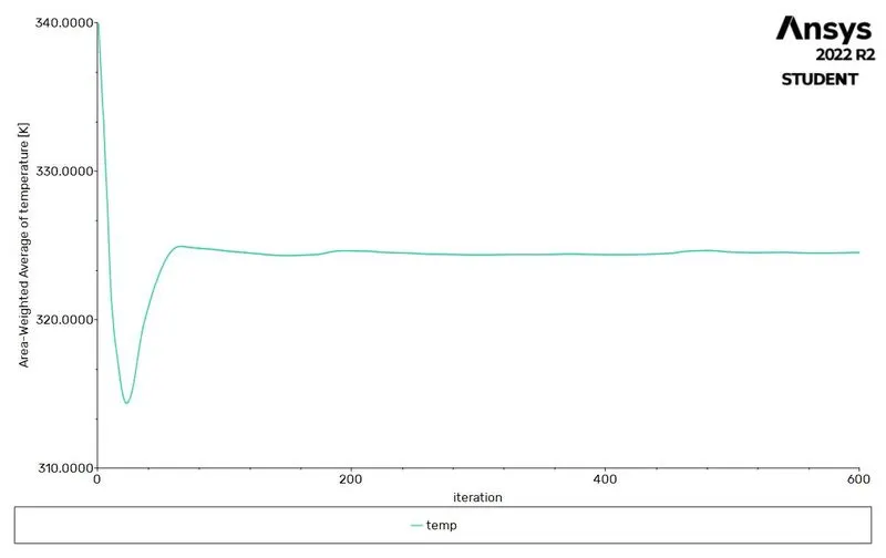
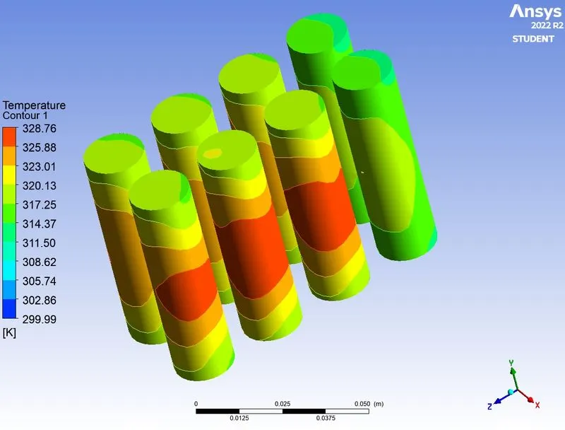
The average temperature of the battery is 324K
The average heat transfer coefficient is -68.37W/m^2K
TEMPERATURE CONTOURS
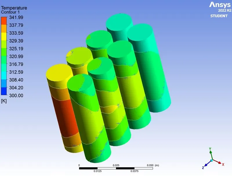
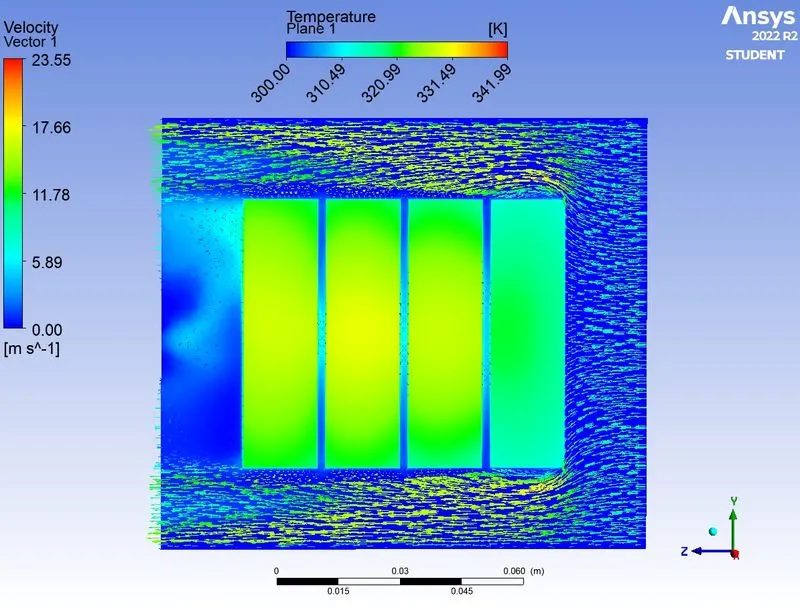
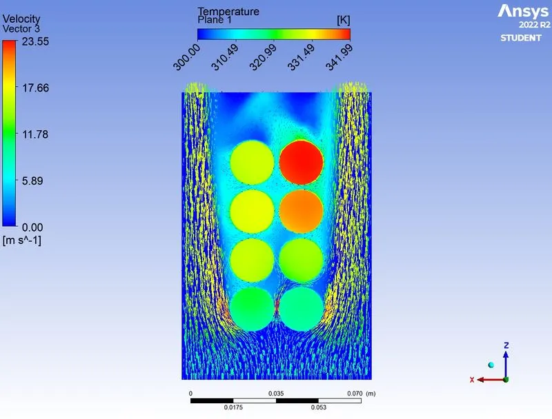
- From the above case studies with battery spacing for 2 mm, we observed forced convection for different speeds and effective cooling is observed at 10 m/s.
- Now let's look at the different space between the batteries which is 4 mm and 6 mm, considering the speed of 10 m/s. (Since I have already analyzed for 2mm spacing, let's analyze for 4mm and 6mm)
STUDY 3:
VARYING THE SPACE BETWEEN THE LITHIUM-ION BATTERIES(STEADY STATE ANALYSIS)
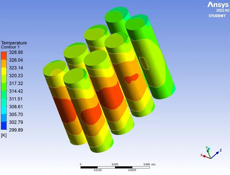
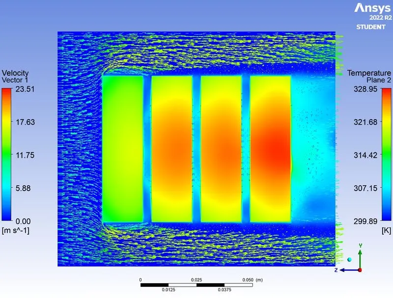
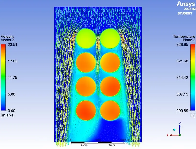
CASE 1: The Space between the battery is 4mm with a forced convection velocity of 10m/s
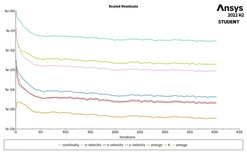
CONVERGENCE
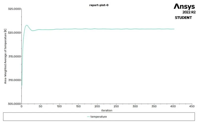
TEMPERATURE PLOT
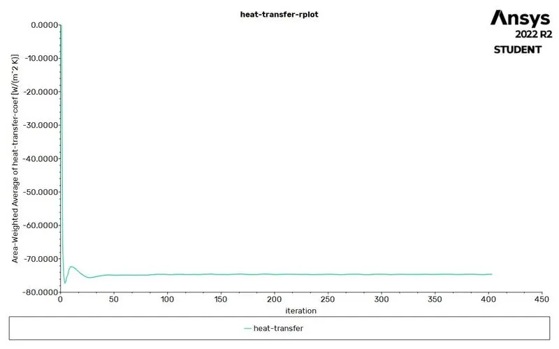
HEAT TRANSFER COEFFICIENT PLOT
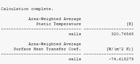
The average temperature of the battery is 320.765K
The average heat transfer coefficient is -74.618W/m^2K
TEMPERATURE CONTOURS
GIF:
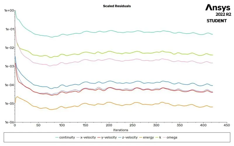
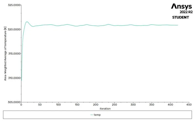
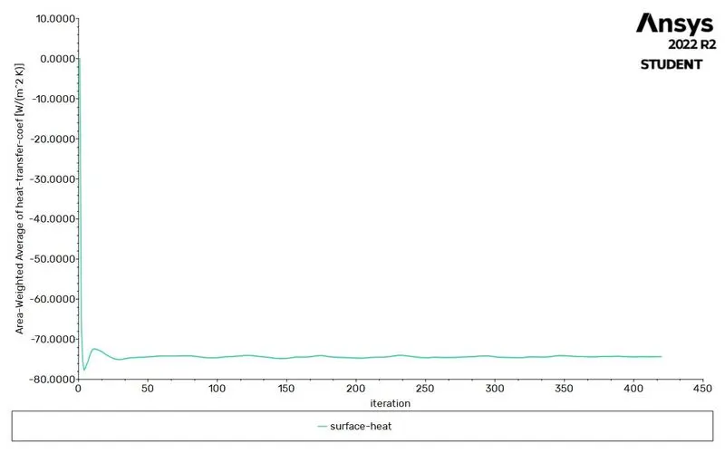
CASE 2: The space between the battery is 6mm with a forced convection velocity of 10m/s
CONVERGENCE
TEMPERATURE PLOT
HEAT TRANSFER COEFFICIENT PLOT
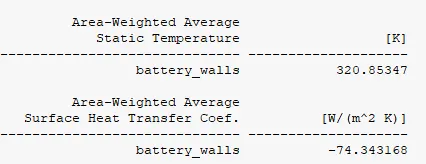
The average temperature of the battery is 320K
The average heat transfer coefficient is -74.343W/m^2K
TEMPERATURE CONTOURS
GIPS:
SIMULATION FOR FORCED CONVECTION WITH VELOCITY OF 3, 5, and 10m/s(SPACE BETWEEN BATTERIES IS 2mm-STEADY STATE ANALYSIS)
| SERIAL NO | VELOCITY(m/s) | HEAT TRANSFER COEFFICIENT(W/m^2K) | TEMPERATURE(K) |
| 1 | 3 | 33.45 | 353 |
| 2 | 5 | 51.25 | 336 |
| 3 | 10 | 68.37 | 324 |
VARYING THE SPACE BETWEEN THE LITHIUM-ION BATTERIES(STEADY STATE ANALYSIS) WITH VELOCITY=10m/s
| SERIAL NO | SPACING(mm) | HEAT TRANSFER COEFFICIENT(W/m^2K) | TEMPERATURE(K) |
| 1 | 2 | 68.37 | 324 |
| 2 | 4 | 74.618 | 320 |
| 3 | 6 | 74.343 | 320 |
CONCLUSIONS:
- In an independent mesh study, we can deduce that to get accurate results, we need to reduce the size of the mesh element, as we see from the above case study, from 8 mm to 3 mm. But here there is not much difference in the results, so we can go with the optimal mesh size (3 mm - more, the calculation time of the mesh elements is longer).
- For lithium-ion batteries, 2mm space between the batteries and effective forced convection cooling were performed with velocities of 3, 5 and 10 m/s. For 10m/s cooling is more efficient compared to other speeds with 324K temperature.
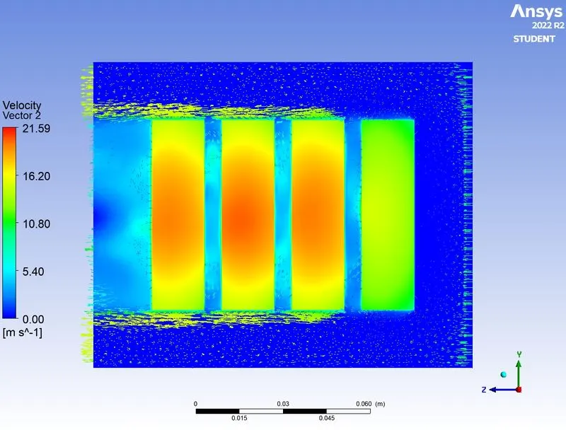
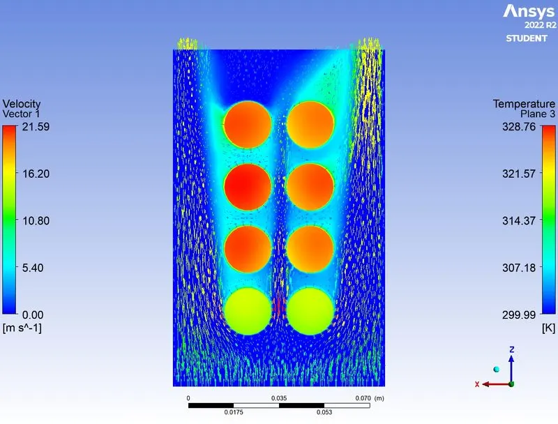
- From the above conclusion, I considered 10 m/s to be the best cooling, so we will study by changing the space between the batteries 2, 4 and 6 mm. Thus, effective cooling was observed in all cases, but there are red hot spots at the last end of the two batteries in the 2 middle parts as shown in the figure (high temperature) for the 4mm and 6mm cases. Therefore, the optimal distance for lithium-ion batteries is 2 mm.
- In conclusion, I would like to say that for lithium-ion batteries, 2mm space between batteries with 10m/s forced flow cooling is an effective way to cool a 4*2 battery module.