Week-6 : Turbocharger Modelling
What does the word Turbocharger mean?
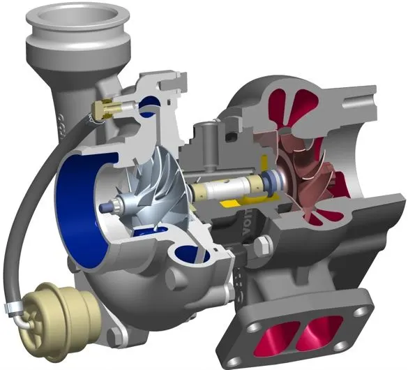
- A turbocharger (or turbo) is a turbine-driven, forced-intake device that increases the efficiency and power of an internal combustion engine by forcing additional air into the combustion chamber.
- This improvement in naturally aspirated engine performance is due to the fact that the supercharger can force more air into the combustion chamber – and proportionally more fuel – than atmospheric pressure alone.
- In naturally aspirated piston engines, the intake gases are "pushed" into the engine by atmospheric pressure, which fills the volume cavity caused by the piston's downward stroke (creating a low-pressure region), similar to drawing liquid into a syringe. .
- The purpose of a turbocharger is to improve engine efficiency by increasing the density of the intake gas (usually air), thereby allowing more power per engine cycle.
- The turbocharger compressor sucks in ambient air and compresses it before it reaches the intake manifold under increased pressure. This results in more air entering the cylinders on each intake stroke. The power required to spin the centrifugal compressor is derived from the kinetic energy of the engine's exhaust gases.
- A turbocharger can also be used to increase fuel efficiency without increasing power. This is achieved by recovering the waste energy in the exhaust gas and feeding it back to the engine intake. By using this otherwise wasted energy to increase the mass of the air, it is easier to ensure that all the fuel is burned before venting at the start of the exhaust stage.
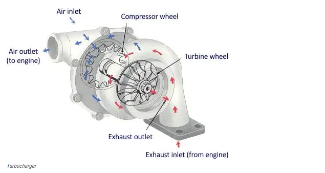
Turbocharger Operation:
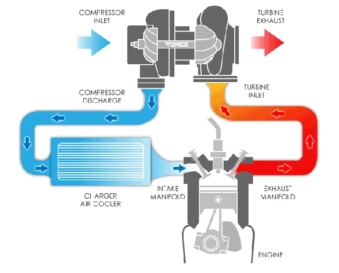
- The turbine drives the compressor as both are mounted on the same shaft.
- The compressor draws in air from the atmosphere and compresses it, forcing the compressed air into the engine.
One end of the turbo air inlet is connected to an air filter that draws in air. - So this air goes through the compressor and voila! a turbo compresses atmospheric air. (the average supercharged engine from the factory compresses the air by up to 4-5psi).
- Here there is an increase in the temperature of the atmospheric air due to compression and the temperature of the exhaust gases.
- The air now passes through the intercooler to cool the air. Hot air can lead to pre-ignition or knocking in the engine.
From the intercooler, air now enters the intake manifold and then the engine. - During fuel injection, combustion takes place in the working stroke.
And further during the exhaust stroke, the exhaust gases force the turbine to spin and the cycle repeats itself again.
Several different types of turbochargers are used in the automotive industry:
- One- Turbo
- Twin-Turbo
- Twin-Scroll Turbo
- Turbo with variable geometry
- Variable Twin Scroll Turbo
- Electric Turbo
single turbo
One turbochargers are what most people think of when they think of a turbo. By varying the size of the elements within the turbo, completely different torque characteristics can be achieved. Large turbos provide higher levels of power at the top end, while smaller turbos can steer faster and provide better low-end performance. They are a cost-effective way of increasing engine power and efficiency, and as such are becoming increasingly popular, allowing smaller engines to increase efficiency by producing the same power as larger naturally aspirated engines, but with less weight. However, they tend to work best in a narrow rev range, and drivers often experience "turbo lag" until the turbo starts working in its maximum rev band.
Twin-Turbo:
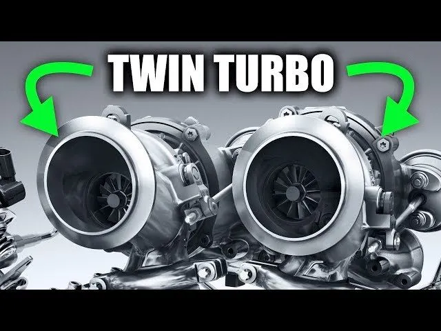
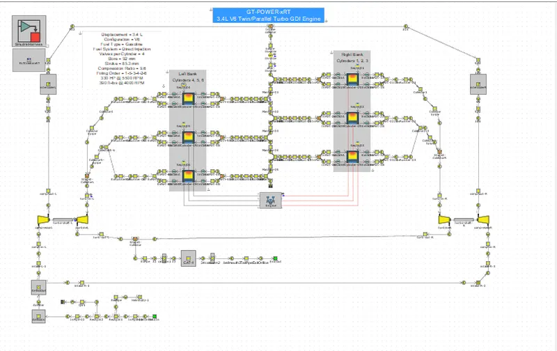
As the name suggests, twin-turbos means adding a second turbo to the engine. In the case of V6 or V8 engines, this can be done by assigning one turbo to work with each bank of cylinders. Alternatively, one smaller turbo can be used at low revs and a larger turbo for higher revs. This second configuration (known as twin sequential turbocharging) allows for a wider range of operating speeds and provides better low-end torque (reducing turbo lag), but also provides high-end performance. Not surprisingly, having two turbos greatly increases the complexity and associated costs.
Twin-Scroll Turbo:
Twin-Scroll turbos require a split-inlet turbine housing and exhaust manifold to pair the correct engine cylinders with each scroll. independently. For example, in a four-cylinder engine (with a 1-3-4-2 firing order), cylinders 1 and 4 may feed into a single turbo coil, while cylinders 2 and 3 feed into a separate coil. This arrangement provides a more efficient delivery of exhaust gas energy to the turbo and results in helping to deliver denser, cleaner air to each cylinder. More energy is sent to the exhaust turbine, which means more power. Again, there is a price penalty for dealing with the complexity of the system requiring complicated turbine housings, exhaust manifolds and turbos.
Turbo with variable geometry:
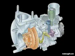
Typically, VGTs contain a ring of aerodynamically shaped blades in the turbine housing at the turbine inlet. In passenger car and light commercial vehicle turbochargers, these vanes rotate to vary the gas swirl angle and cross-sectional area. These internal vanes change the turbo's area-to-radius (A/R) ratio to match engine speed, delivering peak performance. A low A/R ratio at low revs allows the turbo to spin up quickly by increasing exhaust gas velocity and. At higher revs, the A/R ratio increases allowing for increased airflow. This results in a low boost threshold reducing turbo lag and providing a wide and smooth torque band.
While VGTs are more commonly used in diesel engines where the exhaust gases are at a lower temperature, until now VGTs have been limited in gasoline engine applications due to their cost and the requirement for components to be made from exotic materials. The high temperature of the exhaust means that the vanes must be made of exotic heat-resistant materials to avoid damage. This limited their use to applications in luxury, high-performance engines.
Variable Twin Scroll Turbo:
As the name suggests, the VTS turbo combines the advantages of a twin-scroll turbo and a variable geometry turbo. It does this by using a valve that can redirect the exhaust air flow to only one coil, or by changing the size the valve opens, it can allow the exhaust gas to be split into both coils. The VTS turbo design provides a cheaper and more robust alternative to VGT turbos, meaning it is a viable option for petrol engine applications.
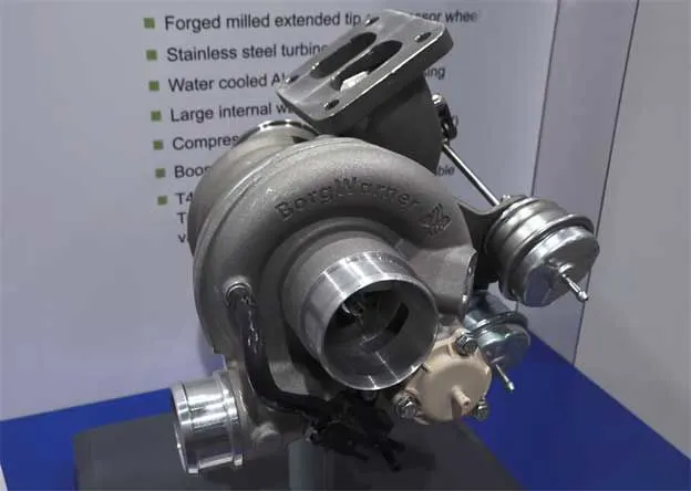
Electric turbochargers:
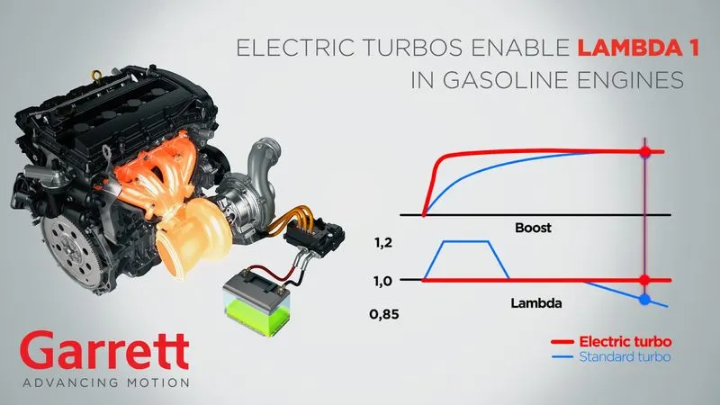
The electric turbo is used to eliminate turbo lag and assist the normal turbo at lower engine speeds where a conventional turbo is not the most efficient. This is achieved by adding an electric motor that spins the turbocharger from start up and through the lower revs until the output from the exhaust volume is high enough to run the turbocharger. This approach makes turbo lag a thing of the past and greatly increases the rpm range in which the turbo will operate effectively. So far so good. Electronic turbos seem to be the answer to all the negatives of conventional turbos, however there are some drawbacks. Most are related to cost and complexity, as the electric motor must be located and powered, as well as cooled to avoid reliability issues.
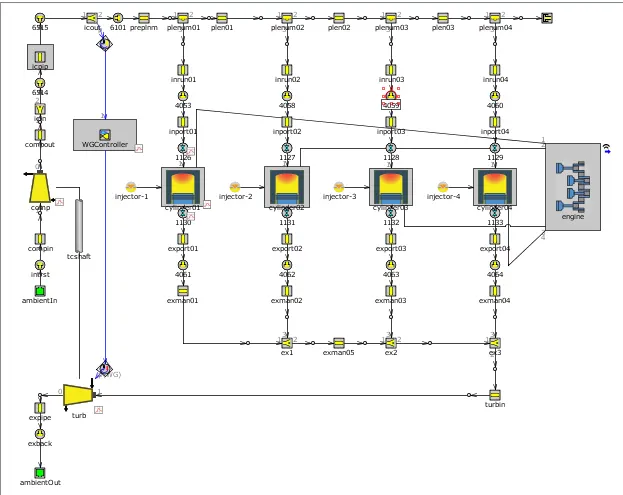
Waste Gate Turbocharger:
A wastegate is a valve that directs the flow of exhaust gases to the turbine wheel in a turbocharged engine system
The diversion of exhaust gases regulates the speed of the turbine, which in turn regulates the speed of the compressor. The primary function of the wastegate is to regulate the maximum boost pressure in the turbocharger systems, protecting the engine and turbocharger. One of the benefits of installing a remote-mount wastegate on a free-floating (or non-WG) turbo includes the option of a smaller A/R turbine housing, resulting in a shorter delay for the turbo to start spooling up and creating boost.
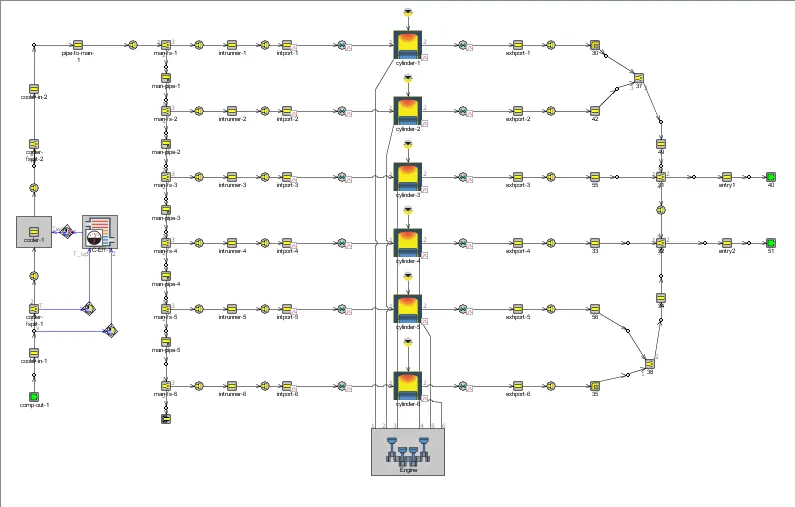
Tutorial-6:
This model consists of 6 cylinders with Turbo Charger implementation, that is, 2 inlets to the turbo, as we can see in the form of two end environments on the right side and the output of the compressor below in the form of an end environment. Generally, Twin Turbine intakes are used with more than 3 cylinders. In this case, we have 6 cylinders, where the turbine inlet is divided into 3 cylinder outputs. Using the Flow Split Template we were able to combine the outputs of the different cylinders. Here, since there is no physical shaft connecting the turbine and the compressor, we directly enter the output pressure values (Absolute) for both the turbine and the compressor. Here the inputs to the turbine and compressor are absolute pressure, temperature and air composition.
In the picture below we see a 6 cylinder engine
Tutorial-7:
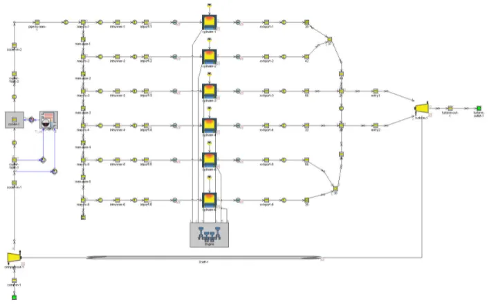
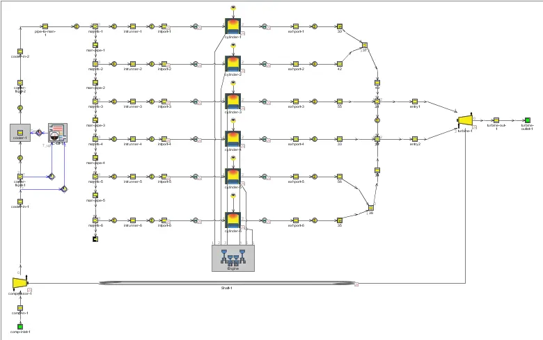
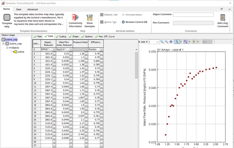
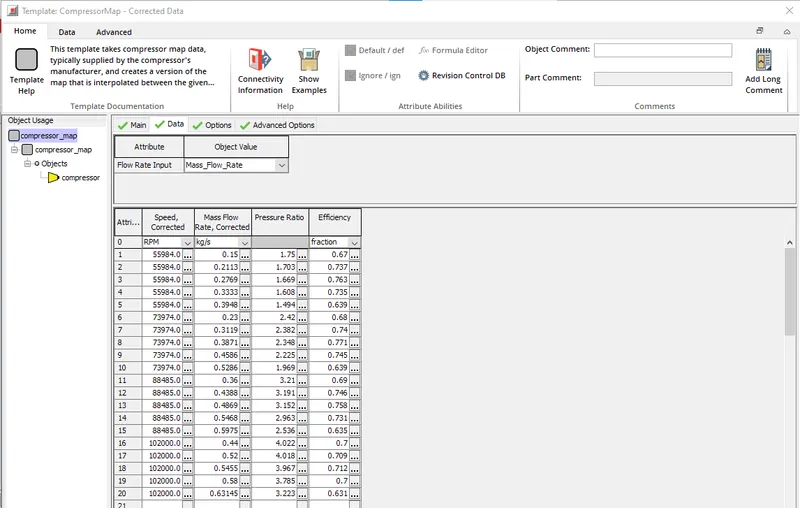
In this model we again have a 6-cylinder diesel engine with two inlets to the turbocharger, which is a set of 6 cylinders divided into 2 inlets. This model is conceptually the same as the above model in tutorial #6 with the actual turbocharger arrangement implemented here where the turbine is connected to the compressor impeller with a rotating shaft as seen in the image below. Here for the turbine and compressor inlets, we have the turbine and compressor map, which is a contour plot of pressure ratio v/s mass flow rate. This turbine and compressor map data consists of parameters such as rotational speed, mass flow rate, pressure ratio and efficiency.
In the picture below we see a 6 Dual Twin Turbocharger Cylinder engine
Understanding Compressor Maps - Turbo Sizing:
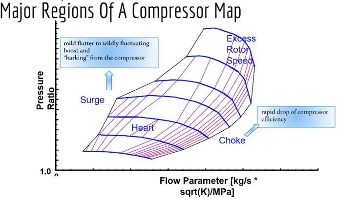
Horizontal axis:
- The lower axis represents the corrected mass flux. That much air flows through the turbocharger per unit of time. This could be rated in kilograms per second or pounds per minute
Vertical axis: - The vertical axis represents the compressor pressure ratio. It is calculated by taking the absolute outlet pressure and dividing it by the absolute inlet pressure. (Note that most gauges read as overpressure, i.e., zero psi at atmospheric pressure, when it's actually around 14.7 psi.) Because of how it's calculated, there are no units associated with this axis. “Pressure ratio is what pressure a compressor stage develops at a given speed relative to atmospheric pressure along with inlet conditions (filter limitations). A pressure ratio is used instead of boosting because atmospheric pressure changes with altitude and weather conditions,” explains Temple.
Data:
- If you are familiar with a topographical map, the data may look familiar. If you're not, each ring represents a certain level, or in this case, efficiency. As efficiency increases, the rings get smaller and smaller.
In the turbocharger industry, these rings are called efficiency islands. The efficiency of a turbocharger is measured by its ability to compress air without adding excessive heat. The higher the efficiency, the lower the outlet temperature for a given charge pressure (it will still be above ambient temperature).
Left Hand Boundaries:
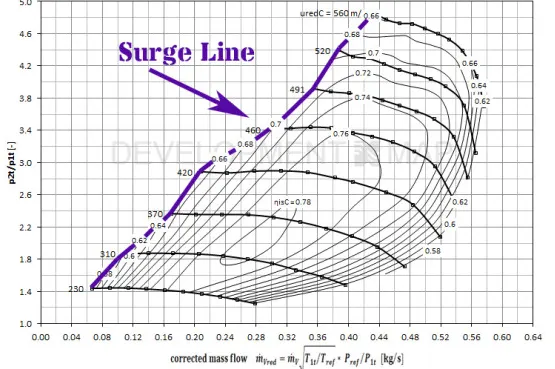
- The rising line of the compressor map is the left border. This line represents the maximum amount of pressure that the turbocharger can create with the least amount of mass (air) flowing.
- Overvoltage can occur in several different ways. The most common and most obvious occurs when the throttle is raised under vacuum, resulting in an audible chirping/coughing sound. As the throttle valve rises under load, the pressure that builds up in the piping system must be released.
- “This is taken into account for OE applications and the appropriate turbo is sized for rated power and surge reserve. This type of knock is more severe on engines equipped with a throttle body after the turbocharger. Throttle bodies are mostly used in gasoline applications, but with newer emissions standards, more diesel engine manufacturers are using them as part of their emissions control strategy. On engines equipped with a throttle body, when the throttle physically closes, the pressure has to be released and unfortunately the only place it has to return is back through the compressor inlet, causing pressure and flow instability”.
- This is why many OE manufacturers integrate a compressor recirculation valve into their system in an attempt to avoid this condition. This is also the reason for the need for aftermarket external blow-off valves. These help relieve the pressure that builds up in the piping system, allowing the turbo to decrease in speed more slowly, which helps extend the life of the turbo.
Right Hand Boundaries:
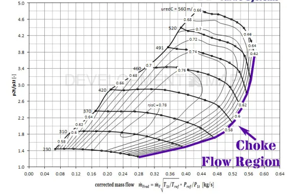
- The opposite of overvoltage is choke. The throttle is basically the maximum amount of air that can flow from the compressor side at a given pressure ratio.
- “As the compressor starts to enter the choke area of the map, the compressor outlet temperatures will increase rapidly, as will the shaft speed. This happens when you reach maximum turbo flow. A turbocharger is typically sized to provide sufficient boost margin while keeping the operating points on the supercharger map in areas above 65 percent,” explained Rufini.
Speedways:
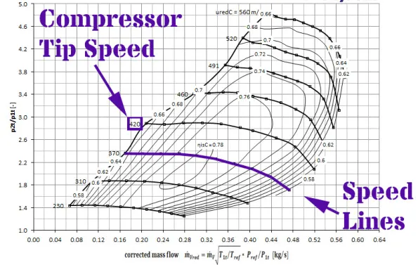
- The speed lines are the last additional bit of information contained in the compressor map. The speed lines run from left to right across the efficiency islands and represent the specific speed of the compressor. These speed lines are usually measured and identified in meters per second, feet per minute, or rotational speed.
Operating points on compressor and turbine maps:
Turbine_Plots:
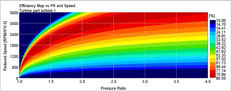
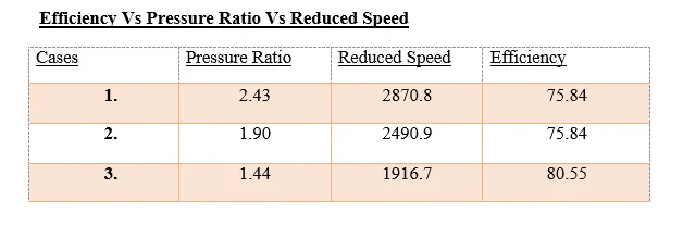
Ratio of efficiency versus pressure versus reduced velocity
Reduced mass flow versus pressure versus efficiency
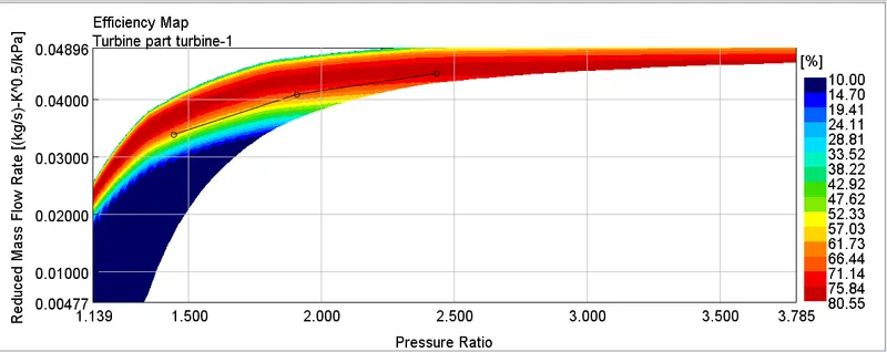
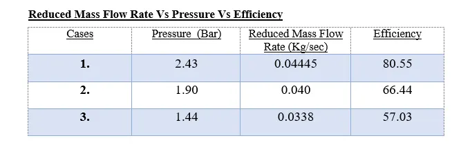
- Above is an efficiency map for a turbine with a mass flow ratio of v/s. For the 1st case, we get a pressure ratio of 2.43 for a mass flow rate of 0.045 kg/s.
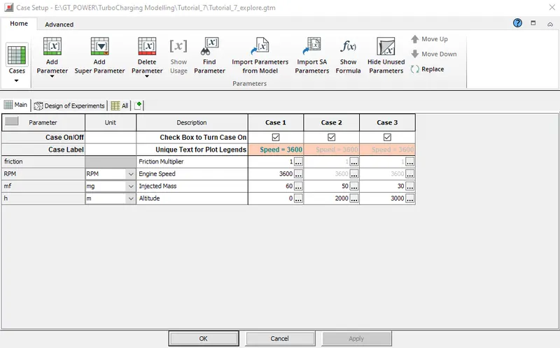
- For the 2nd case we get a pressure ratio of 1.9 for a mass flow rate of 0.040 kg/s, for the 3rd case we get a pressure ratio of 1.44 for a mass flow rate of 0.0338 kg/s. Here the mass flow remains the same but the pressure ratio drops at 3600 rpm. From the contour graph, we can conclude that the achieved efficiency of the turbine falls into the maximum zone, i.e. 80.55%.
Compressor surfaces:
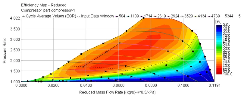

- The compressor map above is a ratio of pressure vs. reduced mass flow. The graph has a structure similar to the efficiency shown in colored bands and black lines as the speed of the compressor.
- The speed achieved by the compressor, whose turbine is also running, when both are engaged, is around 5156 rpm.
The boost line is the operating threshold for the turbo, i.e. to the left edge of the dome, operation beyond this limit leads to fluttering vibrations. - The choke is the maximum operating condition for the turbo, i.e. on the right edge of the dome, causing damage and faster wear. Also from the graph we can see that the compressor is working with an efficiency close to 72-75%.
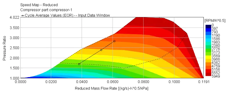
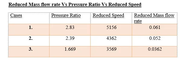
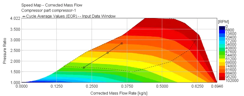
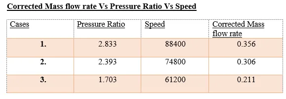
Corrected mass flow vs pressure vs velocity
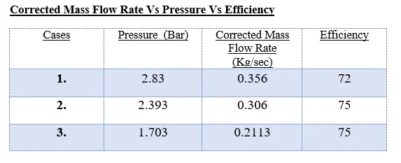
Corrected mass flow vs pressure vs efficiency
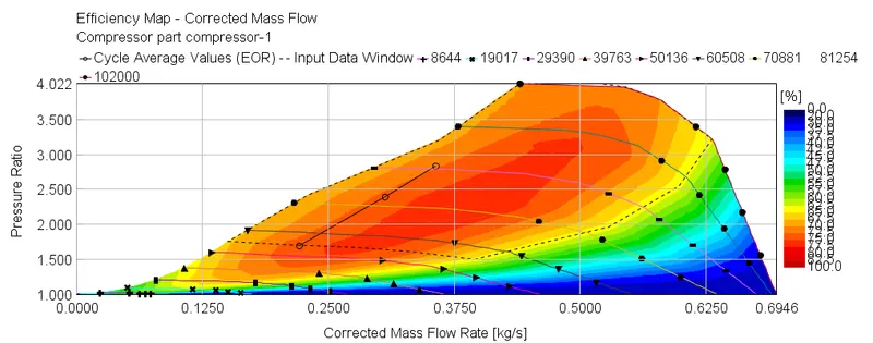
- The compressor map above is a ratio of pressure vs. corrected mass flow rate. The graph has a structure similar to the efficiency shown in colored bands and black lines as the speed of the compressor.
- The speed achieved by the compressor, whose turbine also operates when both are coupled, is around 88,400 rpm.
- The boost line is the operating threshold for the turbo, i.e. to the left edge of the dome, operation beyond this limit leads to fluttering vibrations.
- The choke is the maximum operating condition for the turbo, i.e. on the right edge of the dome, causing damage and faster wear. Also from the graph we can see that the compressor is working with an efficiency close to 72-75%.
In what application is a variable geometry turbine advantageous?
- VGTs tend to be much more common in diesel engines as the lower exhaust temperatures mean they are less prone to failure. Earlier petrol VGTs required considerable pre-charging cooling to extend turbo life to a reasonable level, but advances in technology improved their resistance to high temperature petrol exhaust and they began to appear more and more in petrol cars.
- Typically, VGTs are only found in OEM applications due to the level of coordination required to keep the vanes in the most optimal position for any engine condition. However, there are aftermarket VGT controllers and some high-end aftermarket engines. control systems can also control VGTs.
- VGT devices are designed to increase boost pressure at low engine speeds, shorten response times, increase available torque, reduce boost at high engine speeds to prevent engine overcharging, reduce engine emissions, improve fuel economy and extend the overall operating range of the turbocharger.
- This design is mostly limited to small engines and light commercial vehicles (passenger cars, racing cars and light commercial vehicles).
Diesel VGT EGR:
- A variable geometry turbine allows considerable flexibility in the pressure ratio across the turbine. For diesel engines, this flexibility can be used to improve low-rpm torque characteristics, reduce turbo lag and increase EGR flow.
Variable geometry turbochargers are designed to: increase intake air charge pressure at low engine speeds. improve turbocharger response time during transient phases of engine operation. increase the availability of maximum engine torque. - Engine downsizing using turbocharging is a proven method to improve fuel economy by using a smaller engine operating at higher specific engine load levels and higher efficiency. Turbocharging is more challenging for a gasoline engine than for a diesel engine due to higher airflow variability and higher exhaust gas temperature. Although the variable geometry turbine offers the potential to improve low-speed torque, reduce part-load fuel consumption, and provide fast transient response in a downsized gasoline engine, the cost, lifetime, and limited allowable turbine inlet temperature on currently available equipment present challenges for widespread use
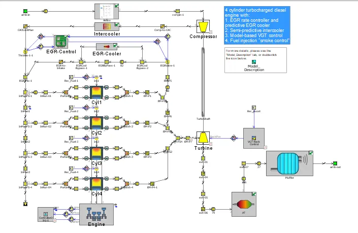
The Diesel VGT EGR model is shown below:
Operation of Diesel VGT EGR:
- It is a 4 cylinder and 16 valve engine with EGR cooler and VGT.
Ambient air is drawn in through the inlet, and then the air passes through the air filters, where the polluted air and dust particles can be cleaned, and the clean air is fed into the compressor from the compressor, the compressed air passes through the intercooler. - In the intercooler, the air temperature decreases and the air density increases, so we will have a higher air flow than the ambient air flow.
- The air from the intercooler passed through the throttle valve where the air passes if the throttle valve is open it means the converter inputs are 90 and if the throttle valve is Close it means the converter inputs are 0.
From the throttle, air is directed through two intake ports into the cylinder where combustion occurs during the Power stroke. - During the exhaust stroke, the exhaust gases and air pass through the exhaust manifold from the exhaust manifold, some of the air went to the turbine and some of the air went through the exhaust gas recirculation (EGR) to reduce NoX emissions.
- The turbine and compressor are connected to one shaft, the air from the turbine passes through a wall flow filter (where diesel and gasoline particles are filtered), from there it passes through the muffler, and the gases are released into the atmosphere through it.
Engine:
- The engine is a 4-cylinder, four-stroke, direct injection, 2L diesel engine. The engine runs in "speed" mode, where the engine speed is entered by the user and the engine torque is calculated.
Combustion is modeled with the DI Pulse method, a predictive combustion model using detailed injection profiles. The heat transfer in the cylinder is modeled using the Woschni model. An FE model is used to predict cylinder, head and piston temperatures. This simulation will run until it reaches steady state convergence for six different engine speeds at full load, three operating points at part load, and another idle point (10 cases in total).
Suction system:
- The intake system consists of an air duct before the compressor inlet and includes a simple air box model. The air chamber is modeled as a group of interconnected flow manifolds that represent the total volume of the air chamber. At the inlet and outlet of the airbox, "bell mouth" throat joints are used to model smooth transitions.
Intercooler:
- The intercooler is located after the compressor outlet. This intercooler is an air-to-air intercooler that is modeled using a "semi-predictive" method based on heat exchanger efficiency.
Note that if heat exchanger performance data is available, it is generally preferred to model the heat exchanger using "Hx Master" and "Hx Slave" parts (which will use the available data to create dimensionless Nusselt correlations defining the heat exchanger performance). This approach will generally extrapolate better than predicted efficiency to conditions beyond those shown in the heat exchanger data. However, if heat exchanger data is not available (or if the simulation will be run under conditions where the HX efficiency is well known), the semi-predictive efficiency method is appropriate.
Suction pipe:
- The intake manifold is modeled as aluminum using thermally conductive objects to calculate wall temperatures. This is important for turbocharged models as wall temperatures can vary substantially at different operating points and thus affect the cylinder inlet temperature. Holes that connect. The initial conditions are different from the ambient conditions. Initial temperatures and pressures are specified at the expected fill pressure to reduce convergence time.
Fuel injection system:
Fuel is injected directly into the cylinders. Both the injection timing and the injection profile are found using the dependence of RLT' as a function of engine speed and injection rate. There is a simple control system that determines the total mass of fuel injected (mg/stroke). This control system starts with the "Signal Generator" part, which stores the input of the accelerator pedal position. The "required fuel weight" is then found as a function of engine speed and pedal position. In some cases, the required weight of fuel can produce excessive smoke if the boost pressure is not high enough to provide enough air. Therefore, the maximum permissible fuel weight is sought as a function of engine speed and boost pressure. The 'Min Max' section is used to specify the lesser of the required fuel weight and the smoke limited fuel weight. This value is then stored to the injectors by the controller.
Exhaust system:
- The exhaust pipe is modeled as cast iron using heat conduction objects to calculate wall temperatures. This is very important in the exhaust manifold because the wall temperatures change substantially between full load and idle, thus affecting turbine inlet temperatures and turbine performance. The holes that connect the exhaust ports to the runners do not allow heat to pass between the pipe walls of adjacent parts. This is necessary because the wall temperature is calculated in the exhaust pipes while it was stored in the hole (the stored value is artificially high to account for heat transfer from the valve). The initial conditions are different from the ambient conditions. Initial temperatures and pressures are specified at the expected back pressure to reduce convergence time. The turbine part refers to the map file from which the map data will be loaded.
EGR system:
- The model includes an exhaust gas recirculation (EGR) system to transport exhaust gases from the exhaust manifold back to the intake manifold. The EGR flow is controlled by the positive pressure difference between the exhaust manifold and the intake manifold and is controlled by the throat connection (EGR-valve). The diameter of the EGR valve is determined by the controller and is determined automatically by the "EGR valve regulator" part to achieve the target EGR fraction. The desired EGR fraction is mapped as a function of engine speed and desired BMEP. EGR values in the model reach up to 40% at some operating points. Because of the high EGR rates, it is desirable to cool the EGR gases using a heat exchanger (EGR cooler). When the pressure drop in the EGR system is not sufficient to achieve the target EGR rate, the throttle valve in the intake system, controlled by the PID controller, will increase the pressure difference. This regulator is only active when the EGR valve is fully open.
- The EGR cooler is modeled using 'HxMaster' and HxSlave parts. Boundary conditions on the coolant side are specified. Heat exchanger model inputs include geometry along with measured heat transfer and pressure drop data. During model preprocessing, the measured data is used to generate dimensionless correlations for heat transfer that allow the model to accurately predict
Turbocharger and Boost Controller:
The turbocharger in this model includes a fixed geometry compressor and a variable geometry turbine (VGT). For the VGT, 5 different sets of turbine map data are entered in each of the 5 positions of the VGT stand. The position of the VGT comb is determined by the control system to achieve the target boost pressure ahead of the intake manifold. The boost pressure is sensed and then filtered using the moving average portion to produce an average pressure signal. The model-based controller compares the sensed boost pressure to the target boost pressure and then adjusts the position of the VGT rack accordingly.
Exhaust system:
- The complete exhaust system of the vehicle is modeled behind the turbine outlet. The Diesel Oxidation Catalyst (DOC) geometry is modeled using the "CatalystBricR" part. In this example, only the pressure drop across the DOC is of interest, so no chemical reactions are modeled in the DOC. The inlet and outlet of the DOC must be modeled using a flow distribution because the DOC is actually a bundle of very small tubes.
Right after the DOC is a Diesel Particulate Filter (DPF) using the "DieselParticFilter" part. In this example, only the geometry attributes are specified, so that the correct pressure drop across the filter is modeled, but no soot accumulation or regeneration is modeled. Similar to the DOC, the DPF inlet and outlet must be modeled using flow distribution. - Behind the DOC is the muffler. This muffler was modeled using GEM3D, which allows the complex geometry of the muffler to be entered in the CAD tool and automatically discretized into the GT-POWER model. The muffler in this example is a three-flow muffler with two baffles. The central chamber between the two baffles is filled with wool, and the various inner tubes and baffles are perforated. The .gem file is contained in the directory and can be opened in GEM3D to view the damper. The GEM discretization output is stored in an internal subassembly to keep the main project map clean.