Week 1 : Exploring the GUI of GT-POWER
GT-SUITE is a leading simulation tool with features and libraries targeting a wide range of applications and industries.
It offers engineers features ranging from rapid concept design to detailed system or subsystem/component analyses, design optimization, and root cause investigation.
Why you should choose GT-SUITE
The industry tool of choice
- It is recognized worldwide as the industry standard for system simulations
- Used by most leading OEMs and suppliers
- Highly regarded
A multiphysics platform
The basis of GT-SUITE is a versatile multiphysics platform for constructing models of general systems based on many basic core libraries:
- Flow library (any fluid, gas or liquid or mixture)
- Acoustics library (nonlinear and linear)
- Thermal library (all types of heat transfer)
- Mechanics library (kinematics, multibody dynamics, frequency domain)
- Electrical and electromagnetic library (circuits, electromechanical devices)
- Chemistry Library (Chemical Kinetics)
- Library of Controls (Signal Processing)
- Built-in 3D CFD and 3D FE (thermal and structural)
Modern software with unique capabilities
- Merging 1D and 3D simulation in one tool
- Imports solid models from CAD and creates 1D and 3D models
- Performs embedded 3D CFD and 3D FE thermal/structural modeling with all boundary conditions provided by the simulated ambient complete system
Enterprise level capabilities
- Integration with leading PLM and revision management tools (Siemens Team Center, Microsoft Sharepoint, SVN)
- System integration and collaboration tools
- Includes a tool-neutral co-simulation platform with FMI support (xLINK)
- Distributed computing
- DOE and optimization
High productivity and price advantage
- GT-SUITE includes important and valuable productivity tools included with all licenses at no additional cost.
- A fast solver makes simulations of large systems practical
- Highly regarded customer support is considered the best in the industry
- Highly competitive product prices
- GT-SUITE: Contains all GT libraries and capabilities. The ideal choice for complete vehicle design and analysis, GT-SUITE offers a comprehensive package that provides users with an important cost advantage.
- Engine performance and acoustics
- Exhaust After treatment
- Evaporative emissions
- Cooling systems and thermal management
- Air conditioning/Recovery of waste heat
- Fuel injection
- Hydraulics and pneumatics
- Lubrication circuits
- Vehicle and HEV fuel consumption and performance
- Gearbox and shifting quality
- Crank mechanism and crankshaft dynamics
- Kinematics and dynamics of valve timing
- Timing and front drive systems
- The electrical equivalent of battery modeling
GT-POWER: Top engine simulation software with detailed cylinder model and combustion analysis.
- Engine performance and acoustics
- Exhaust after treatment
- Evaporative emissions
- GT-SUITEmp: Serves as a multiphysics platform for building models in a wide range of applications including cooling systems and thermal management, vehicle and HEV fuel consumption, hydraulics and tires, and many others.
- Exhaust After treatment
- Evaporative emissions
- Cooling systems and thermal management
- Air conditioning/Recovery of waste heat
- Fuel injection
- Hydraulics and pneumatics
- Lubrication circuits
- Vehicle and HEV fuel consumption and performance
- Gearbox and shifting quality
- Crank mechanism and crankshaft dynamics
- Kinematics and dynamics of valve timing
- Timing and front drive systems
- The electrical equivalent of battery modeling
- In addition to the above, GT also offers various tools and models:
Tools:
GT-AutoLion: – Integrate AutoLion battery models directly into the GT-SUITE electrical and thermal area
GT-POWER-xRt:– Tool designed for running detailed models of GT-POWER engines on MiL/SiL/HiL platforms
GT-SUITE-RT:-Run GT-SUITE models on HiL platforms
GT-Automation:-a time-saving enterprise package that allows simulation engineers to write Python code to programmatically manipulate GT models
GT-AutoLion-3D: A 3D battery modeling capability that allows battery designers and buyers to study the important factors that determine battery performance, capacity and lifetime.
GT-TAITherm:- Perform a quick 3D cabin comfort analysis with a special version of TAITherm packed right into the GT-SUITE
Advanced Combustion Toolset: A set of productivity tools for combustion analysis that enable higher model accuracy and faster runs
GT-RealDrive: - Simulate vehicle models on real-world routes, including traffic density, traffic signals and speed limits
GT-CONVERGE:- Built-in 3D CFD supporting co-simulation or stand-alone analysis, both transient and steady state
GT-SPACECLAIM:- Creation and preparation of CAD model
GT-Linearization:- Linearization of control development models
Some of the modules that are used in GT Power are detailed below:
COOL3D:
COOL3D is a tool that can be used to build 3D models of underhood heat flow control systems that can be discretized and made into model files for use with GT-SUITE. It provides the ability to build the model in a 3D environment so that all the details of the model can be included. It also includes sophisticated discretization logic that is able to transform a 3D model into a model file that is compatible with GT-SUITE software. COOL3D can be used to build any flow system that only includes blocking, fans, heat additions and heat exchangers
GT-ISE:-
It is the main interface where models are built and simulations run. It is an environment where all elements are mapped and linked together connecting the whole model. It creates a model in sequential order step by step, such as engine cylinder, engine crankshaft, combustion, valve train, etc.
GEMS 3D:-
GEM3D is a tool that can be used to build 3D models of flow, thermal and mechanical systems that can be discretized to create model files for use with GT-SUITE. It provides the ability to build the model in a 3D environment so that all the details of the model can be included. It also includes sophisticated discretization logic that is able to transform a 3D model into a model file that is compatible with GTSUITE software. GEM3D can be used to build any system that includes components such as pipes, mufflers, manifolds, air boxes, heat exchangers, under the hood, cab, batteries, crankshafts, etc.
GT-POST:-
GT-POST is a powerful data analysis tool used to plot, view and manipulate data generated by a GT-SUITE simulation or an external source. It offers a more efficient data analysis solution than a standard spreadsheet. By using data pointers, the results displayed in GT-POST are updated automatically and immediately when the model is changed and the simulation is restarted. GT-POST also lends itself to developing portable, user-defined templates that control how results are presented.
VT-DESIGN:-
VTDESIGN is a standalone interactive cam/valve/spring design tool provided with GT-SUITE that can be used as a preprocessor for GT-SUITE. VTDESIGN consists of three main functions, including Cam Design function, Valvetrain Design function and Spring Design function. These three functions can be accessed at any time by clicking on the separate tabs in the lower left corner of the project window named "CamDesign", "Valvetrain" and "SpringDesign".
VTDESIGN can be used to create a profile or automatically generate a Multi-Body Dynamic valve train model for analysis in GT-SUITE
GT-SPACECLAIM:-
GT-SPACECLAIM is a tool that can be used to import CAD geometry of various formats, extract volumes and export them for discretization in GEM3D. It is also possible to create and export 3D models of flow systems. These basic shapes that can be created with GT-SPACECLAIM. These shapes are similar to those that can be created in GEM3D and can be combined into complex geometry.
2. Find the settings
TIME CONTROL FLAG
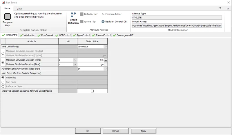
Open the GT_suite GUI and open the flow control tab > Home tab > RunSetup > Time Control. A time control flag is available in the given table
In the image below we can see the Time Control Flag option
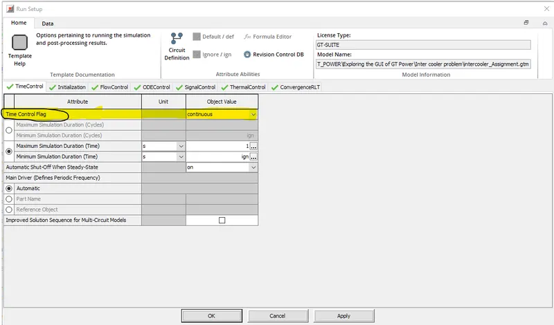
Defines the global simulation type with respect to time. One of the following options:
Periodic: Periodic means that the model contains at least one circuit that contains a periodic event (i.e., an engine cylinder "cycle") and therefore requires tracking the results with respect to the angle in each cycle. Any model that contains an 'EngineCrankTrain', 'CrankAnalysis' or 'CrankShaft' component should use the periodic option. Note that the simulation duration for a periodic simulation can be specified in cycles or time, whichever is most appropriate.
Continuous: Continuous means that the simulation does not involve any periodic event and therefore there is no need to track the results with respect to the cyclic angle. This is a typical setting for models that contain only quasi-steady fluid circuits such as coolant or underhood air. The simulation duration for a continuous simulation is usually specified in time.
TIME STEP AND SOLUTION CONTROL:
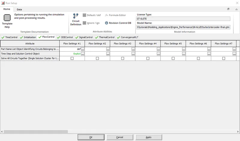
Open the GT_suite GUI and open the Flow Control tab > Home tab > RunSetup > Flow Control. Here we can track the time step and control the solution
In the image below we see the option Time Step and Solution Control
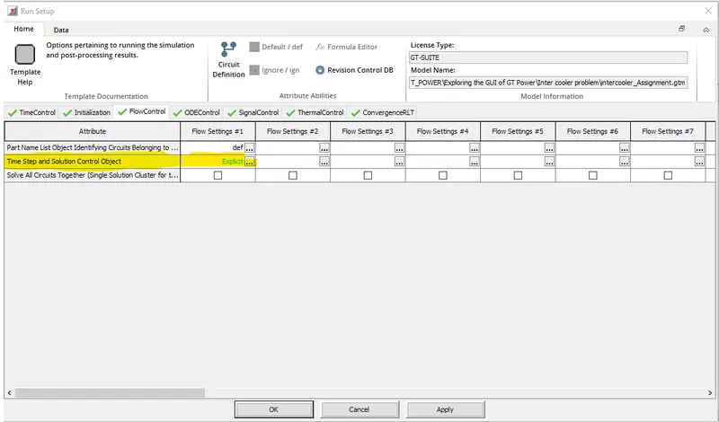
The name of a 'FlowControlExplicit', 'FlowControlImplicit' or 'FlowControlQS' reference object that can be used to define numerical parameters for an explicit, implicit or quasi-steady flow solver.
Starting with V2016 Build 2, this attribute can be set to "ign" or left blank if there are no flow circuits in the model (which is a rare exception to the normal requirement in GT-SUITE that all cells must be filled).
INTEGRATOR/SOLVER TYPE
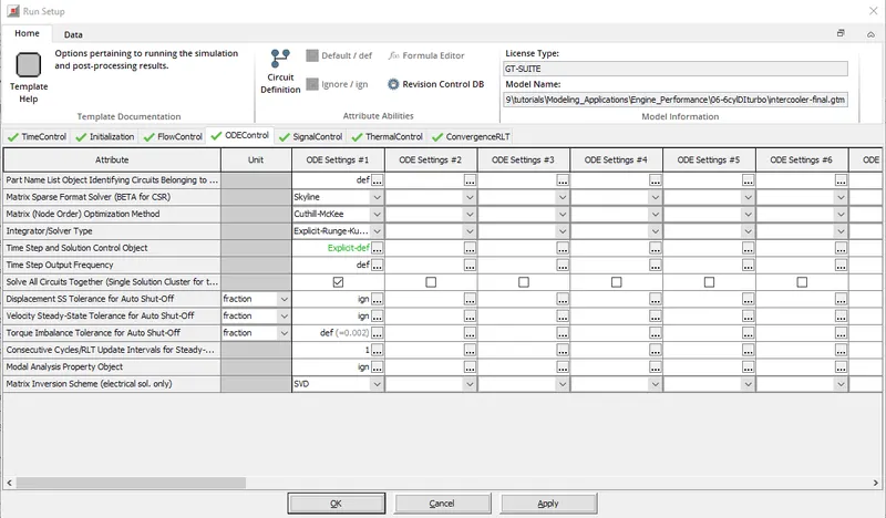
Open the GT_suite GUI and open the flow control tab > Home tab > RunSetup > ODE Control. Here we can observe the integrator/solver type
In the image below we see the Integrator/Solver Type option
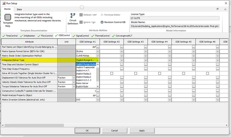
An integrator/solver type used in the timeline of all ODRs including mechanical, electrical, and magnetic libraries. Application-based recommendations can be found in the color-coded table immediately following this text.
Explicit-Adams-PECE: An explicit Adams-Bashforth-Moulton predictor-corrector integration scheme with variable order precision. This integrator is recommended for large non-stiff problems, high maximum time step problems that have different scales, and real-time applications. It requires a debugging process to optimize its functionality, please contact email: [email protected] for more details.
Explicit Runge-Kutta: an integration scheme that is 5th order accurate. This integrator is recommended for non-stiff problems
Implicit Trapezoids: An implicit trapezoidal integration scheme that is 2nd order accurate. This integrator is recommended for moderate problems.
Implicit-H.H.T: An implicit Hilber-Hughes-Taylor integration scheme that is 2nd order accurate. This integrator is recommended for moderate problems.
Implicit-Radau2: An implicit 2-stage Radau integration scheme that is 3rd order accurate. This integrator is recommended for hard problems.
Implicit-Radau3: An implicit three-step Radau integration scheme that is 5th order accurate. This integrator is recommended for hard problems.
Implicit-S.D.C.3: An implicit 3-phase spectral delayed correction (S.D.C.) integration scheme that is 5th order accurate. This integrator is recommended for very hard problems.
3. Explore the Intercooler tutorial and note all the settings:
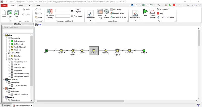
Open the Gt suite and click on Files then select Tutorials then select Engine Performance then 6cylDITurbo then select intercooler_final.gtm
The intercooler settings will appear on the screen.
Run the installer
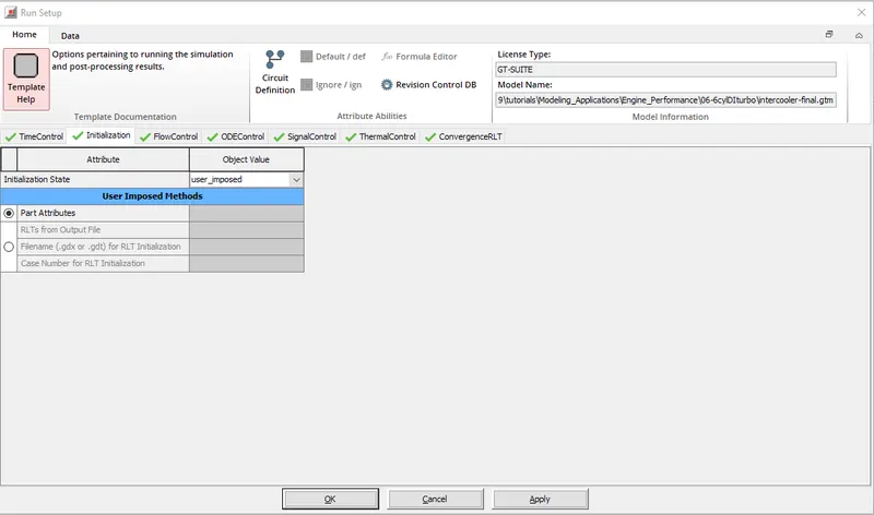
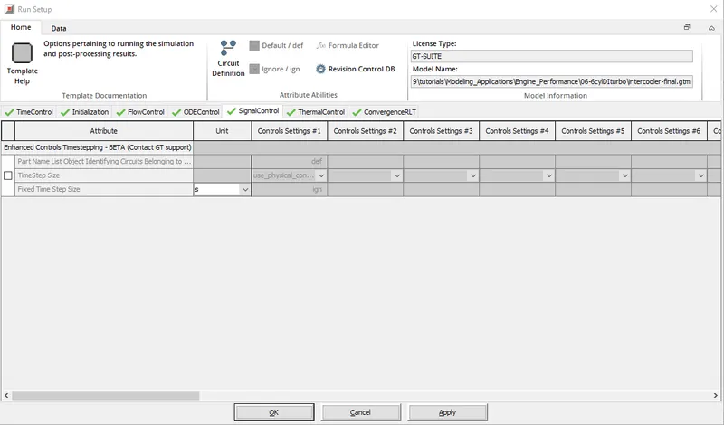
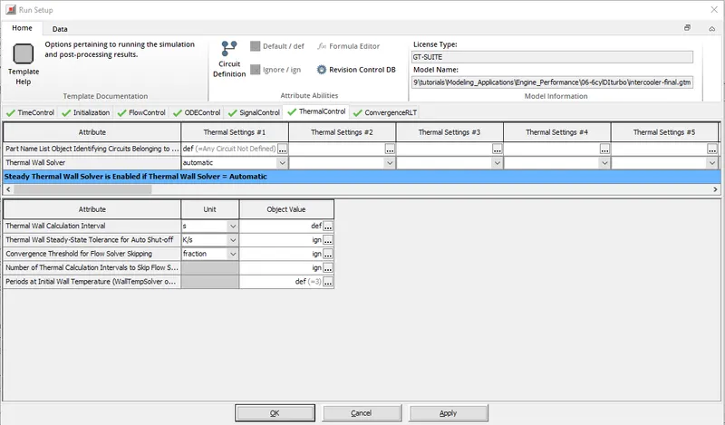
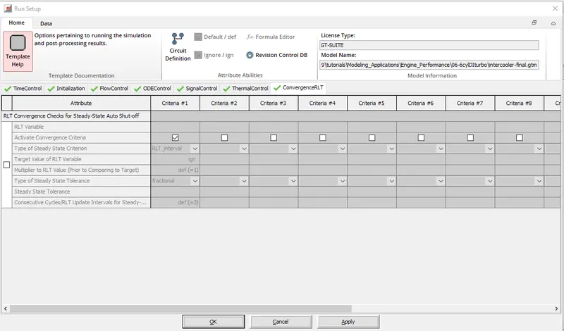
In this module, all settings are made according to our simulation results to get accurate results. It contains various settings like time control, initialization, flux control, ODE control, signal control, temperature control, RLT convergence.- Each setting has different attributes for running the simulation. We can go through all these sections detailed in the images below.
Time control:
Intialization:
Flow Control:
ODE Control:
SignalControl:
Thermal Control:
ConvergenceRLT:
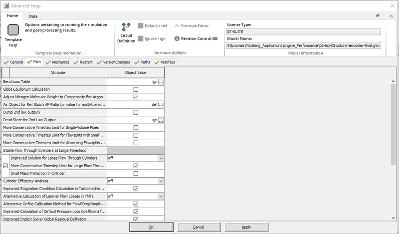
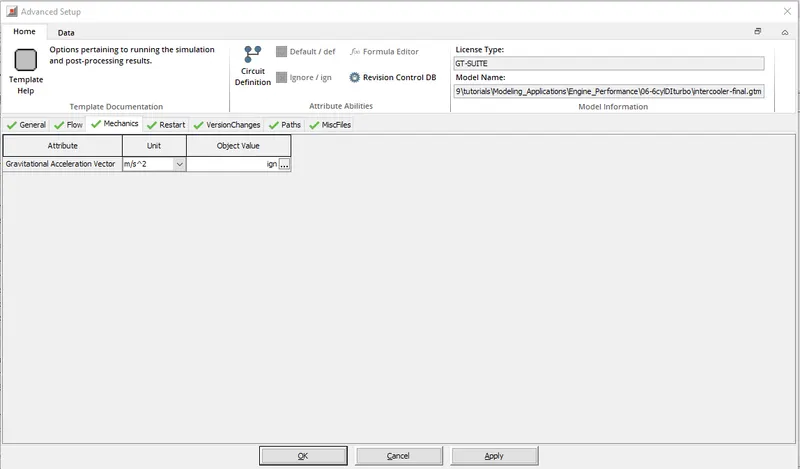
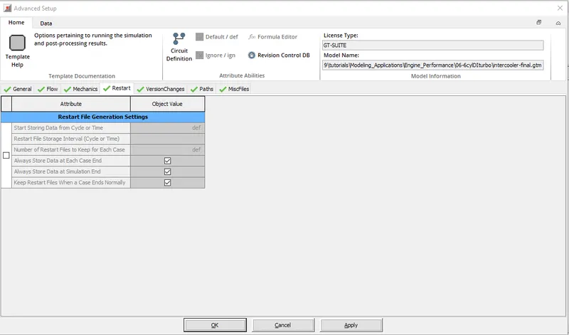
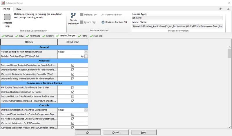
- Advanced Setup
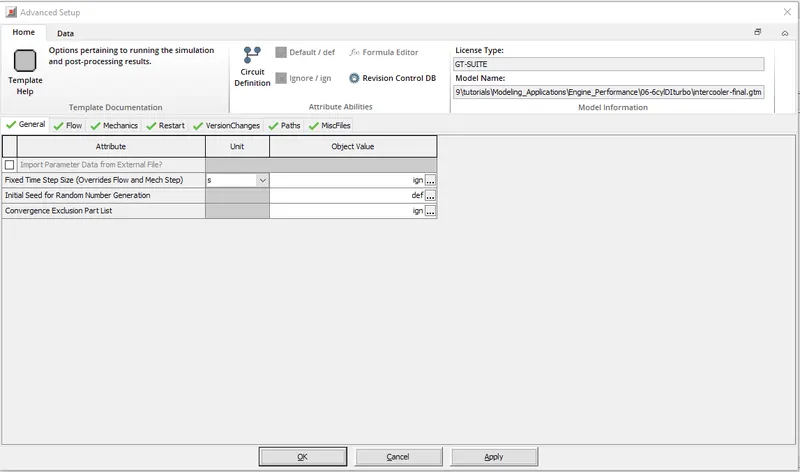
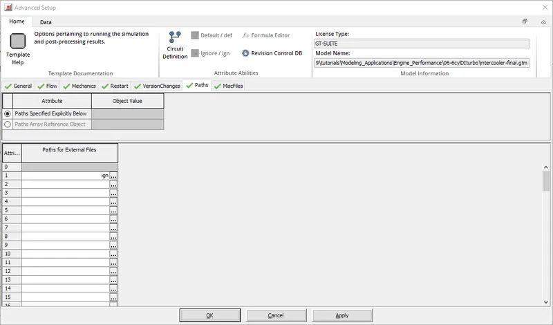
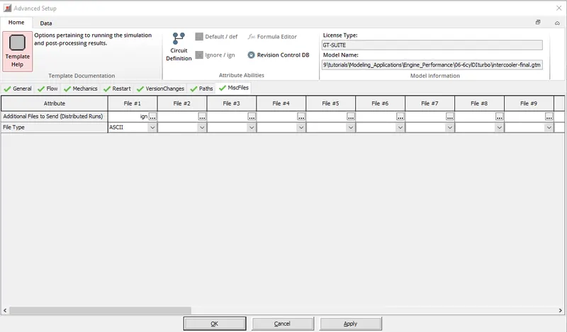
- Advanced Setup also have the different Attributes and we can go through all this sections detailed in the below images.It Contains the different Setups like General,FLow,Mechanics,Restart,Version Changes,Paths,MiscFiles
- Each Settings have a different Attributes to run the simulation.we can go through all this sections detailed in the below images.
General
Flow
Mechanics:
Restart:
Version Changes:
Paths:
MiscFiles:
- Plot Setup
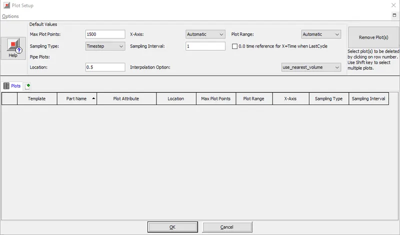
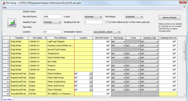
- Cycle and/or time plots may be requested by selecting the appropriate plot from the "Plot Options" folder within each part. Each of these requests will result in a plot being stored. (This is not true when the specific plot requires a certain modeling option to be used in order to calculate the results that are to be presented in the plot. For example, plots of the pipe wall temperature versus radius will be made only when the wall temperature solver is used in the model.)
- Plot Setup, which is found under the "Run" pull-down menu, gives the user a variety of options to change the way in which the plots are requested. If no changes are requested, the Default Values, as specified in the top right corner of the Plot Setup Dialog, will be used. A button called "Remove Plot(s)" is available to remove unwanted plot requests from Plot Setup. All plots requested in individual parts will be stored regardless of whether the user chooses to use Plot Setup.
Output Setup
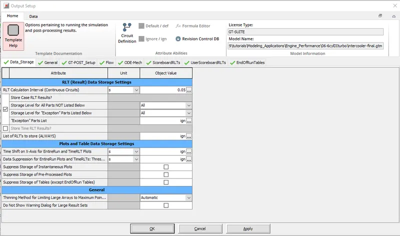
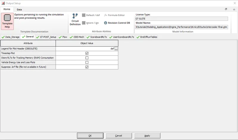
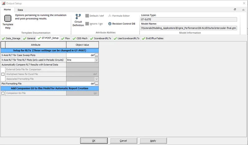
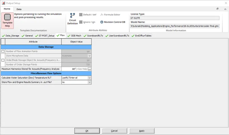
GT_Post processing data can be done it is used for the accesing the data from the results.It Contains the different Setups like Data_Storage,General,GT_POST_Setup,Flow,ODE_Mech,ScoreboardRLTs,UserScoreboardRLTs,EndOfRunTables.
Each Settings have a different Attributes to run the simulation.we can go through all this sections detailed in the below images.
Data_Storage:
General:
GT_POST_Setup:
Flow:
ODE_Mech:
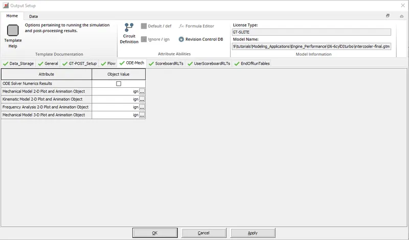
ScoreboardRLTs:
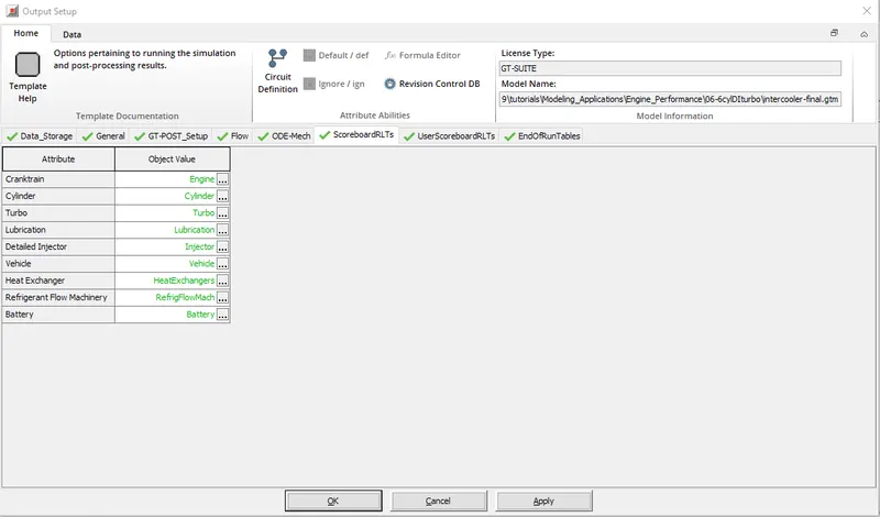
UserboardRLTs:
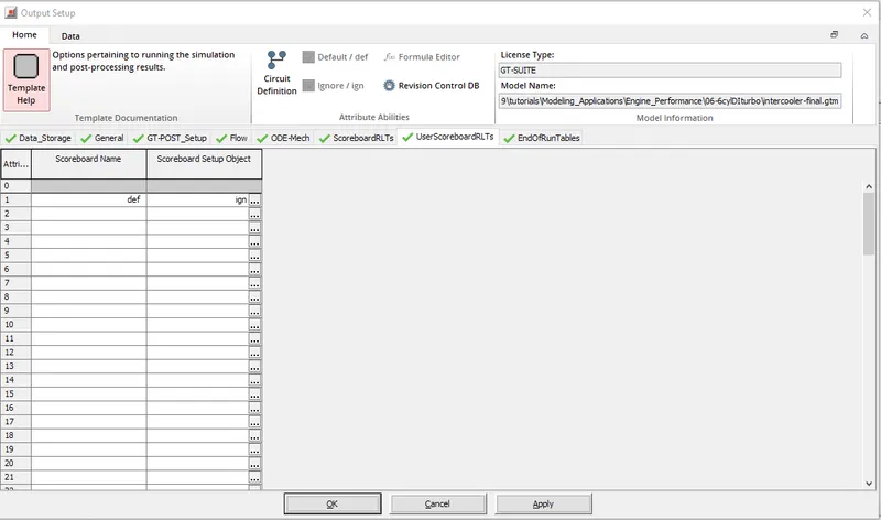
EndofRunTables:
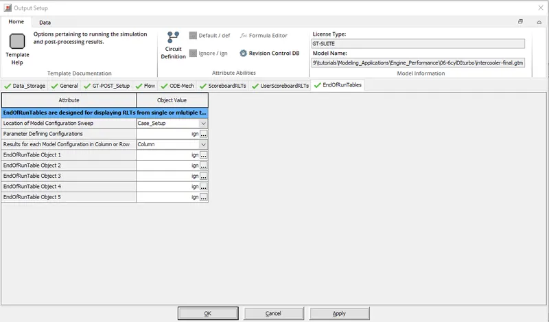
4.Inter Cooler Problem:
- Open the Inter-Cooler tutorial by opening through the following steps.
- File > Tutorials>Engine Performance>06-6cylDITurbo>intercooler_final.gtm
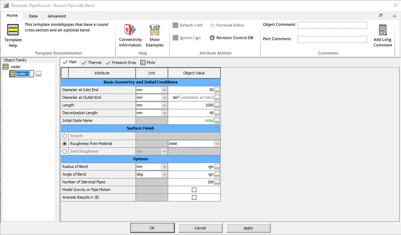
- Now by double clicking on the intercooler-1and box will pop up and change the diameter of the inlet and outlet =50 mm and also the Length of the CAC=1000 mm Which is shown below:
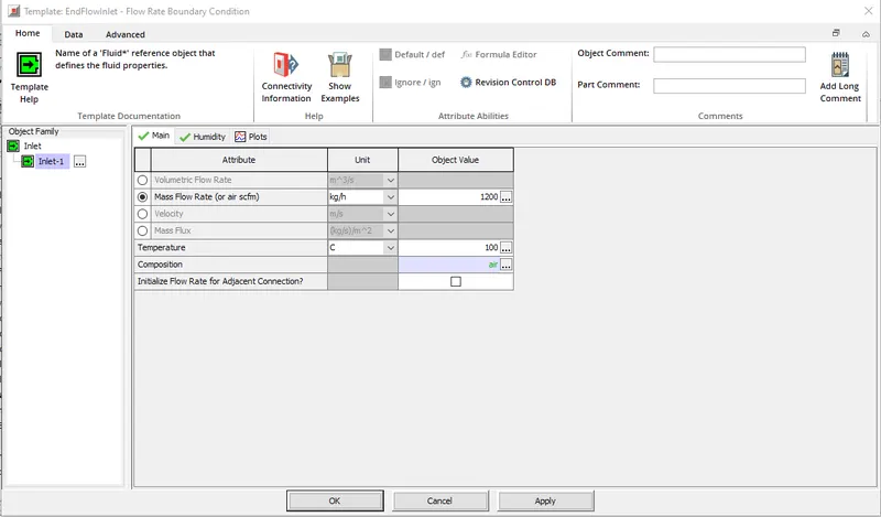
- Now,By double clicking on inlet-1 change the Mass flow rate =1200 Kg/h and temperature =100 deg/C
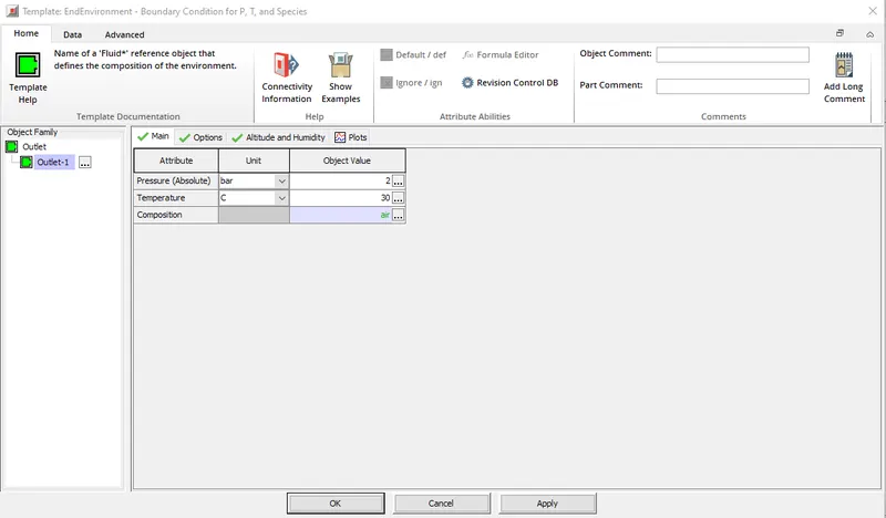
- Now,By double clicking on Outlet change the Pressure =2 bar and temperature =30 deg/C
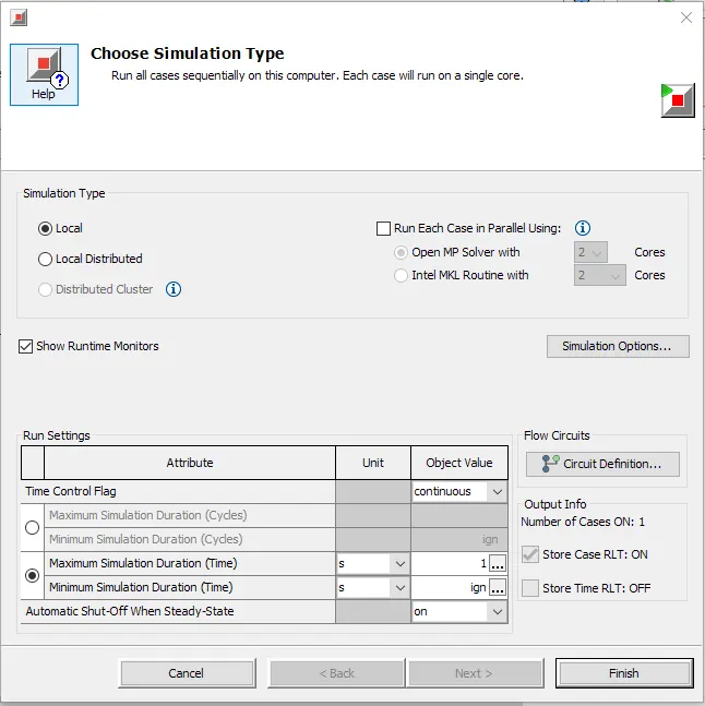
- In the run set up change the simulation time to 1 sec and start the run command in order to start the simulation.
- The total heat Transfer at Charge Air Cooler =7.5539484 Kw
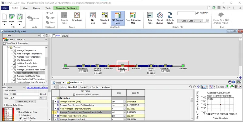
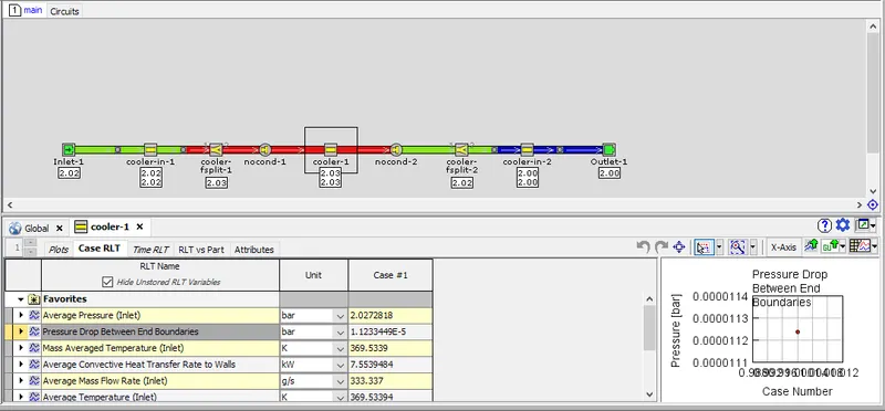
- The Pressure Drop across CAC=1.1233449E-5 bar
Conclusions:
- Thus the GUI of GT Suite format is being explained
- Locations of the different setups is found.
- Elaboration of the different setups is done and explained them.
- For the Intercooler Engine the Temperature and Pressure Drop has been computed