Week 9 - Parametric study on Gate valve.
Aim:
To perform a parametric study on a gate valve at different valve opening settings.
Theory:
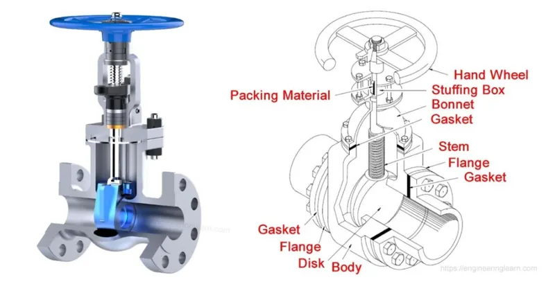
Gate valves work by placing a rectangular gate valve or wedge in the path of the flowing fluid. They are operated by a threaded shaft that connects the drive (usually a handwheel or motor) to the gate shaft. If the valve has a rising stem, its position can be seen just by looking at the position of the stem. A gate valve is used to control fluid flow by raising and lowering the gate valve. The characteristic feature of the closure is to provide an unobstructed passage involving minimal pressure loss across the valve.
When the gate is fully open, there is no flow restriction and therefore the pressure drop is relatively low. Generally, the gate valve is fully closed or fully open, as a partially open valve can experience vibrations that can lead to excessive wear. The main part of the gate valve is the body, seat, gate valve, spindle, cover and drive. the primary mechanism is straight forward where a hand wheel is turned and moves the gate up and down using threads. require more than 360 degrees of rotation to fully open the valve.
Gate valves tend to be slightly cheaper than ball valves of the same size and quality. They are slower to actuate than quarter-turn valves and are intended for applications where valve actuation is infrequent, such as shut-off valves. Gate valves should be used either fully open or fully closed, not for flow control. Automatic gate valves exist with either an electric or pneumatic drive, but a manual gate valve is cost effective as it is not used frequently. Gate valves are widely used for all types of applications and are suitable for above ground and underground installation. They are suitable for most liquids including steam, water, oil and gas etc.
Use:
Gate valves are used to shut off the flow of fluids rather than to regulate flow. When fully open, a typical gate valve has no obstruction in the flow path, resulting in very low flow resistance. The size of the open flow path generally changes in a non-linear manner as the inlet moves. This means that the flow does not change uniformly with the movement of the spindle. Depending on the design, a partially open gate may vibrate from the fluid flow.
Gate valves are mostly used on larger pipe diameters (from 2" to the largest pipe) because their design is less complex than other types of large size valves.
Friction can be a problem at high pressures. When the gate valve is pushed against the guide rail by the medium pressure, the valve is more difficult to operate. Large gate valves are sometimes fitted with a bypass operated by a smaller valve to reduce the pressure before operating the gate valve itself.
Gate valves without an additional sealing ring on the gate valve or seat are used in applications where minor valve leakage is not a problem, such as heating circuits or sewage pipes.
Gate valves are typically constructed of cast iron, cast carbon steel, ductile iron, gunmetal, stainless steel, alloy steel, and forged steel.
Flow coefficient - Cv - or flow factor - Kv - are commonly used to specify the capacities of control valves.
Using the slider:
A typical gate valve application includes
- Cooling water systems.
- Fuel oil systems.
- Power system or chemical feed system.
- Boiler and main steam vents and wastes.
- Turbine Lubricating Oil System.
Flow Co-efficient:
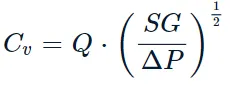
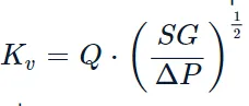
where
- Kv is the flow factor expressed in m^3.h^-1
- Q is the flowrate (expressed in cubic metres per hour m^3/h
- SG is the specific gravity of the fluid (for water = 1),
- ∆P is the differential pressure across the device (expressed in [Bar]).
Kv can be calculated from Cv using the equation:

Steps Followed:
a) Geometry preperation
b) Meshing
c) Setup
d) Results
Part 1:
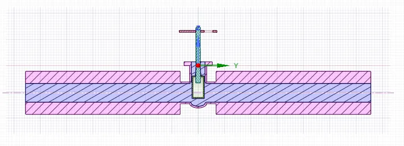
The fixed geometry consists of a bottom cover, a handwheel, a spindle, a lid and a slide. The liquid moves from the inlet to the outlet, a gate valve is used to limit this movement, which is manually operated by turning a hand wheel, which is supported by a lid and connected via a spindle. When a lower outlet mass flow rate is desired, the gate valve is lowered, limiting the fluid mass flow rate at the outlet. The fluid mass flow rate at the outlet varies with the stroke of the gate plug and this needs to be simulated.
Geometry preperation:
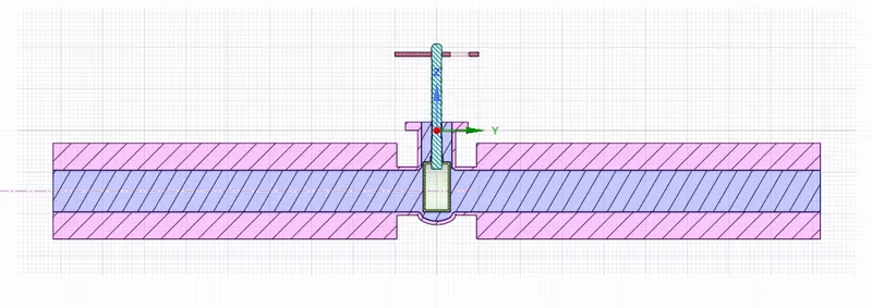
Given 3D model:
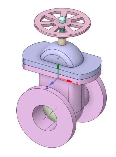
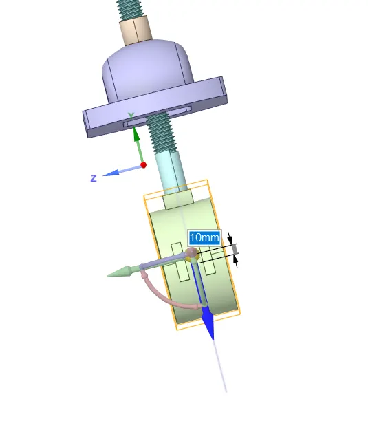
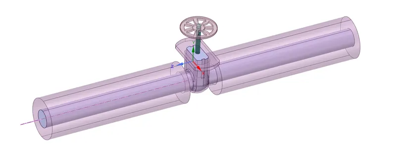
To simulate the effect of the stopper on the mass flow rate of the fluid at the outlet the stopper is moved 10mm in the positive Z-direction so that the flow path is partially open. This is parametrized. Next, the fluid is extracted from the solid geometry. The parameterization helps us change its value and compute the required output parameters without having to repeat the same processes again. Since we are not interested in the analysis of solid geometry, it is suppressed.3D model inlet & exhaust has been extended to accommodate fluid volume necessary to simulate gate valve.
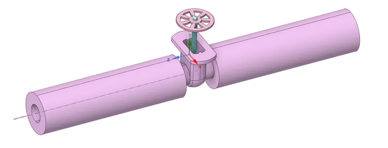
The valve has been opened 10mm to calculate mass flow rate of water.
The fluid volume extracted using Volume extract option by selecting boundaries to make it closed volume.
Final fluid volume
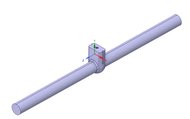
Suppress all the solid volumes.
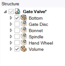
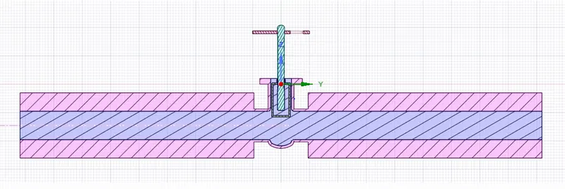
The simulation has been carried out number of valve opening from 10mm to 90mm. The dimension of valve opening has been parameterize to simplify simulation process of similar type with different valve opening. The parameter has been created for valve opening by creating group shown in the below image.
Meshing:
Create Named Selections
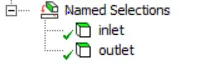
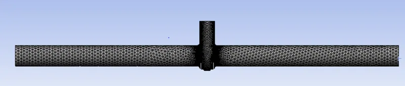
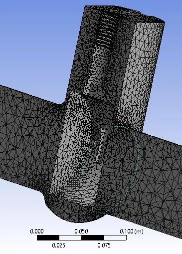
Mesh:
Setup:
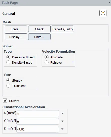
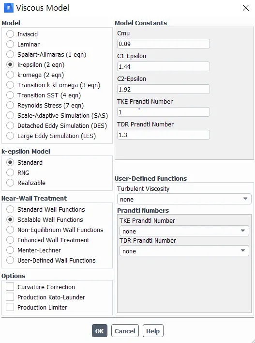
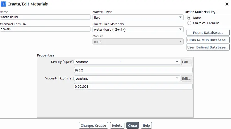
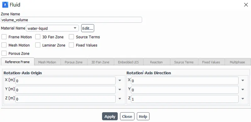
Following options are selected.
Materials:
Cell zones:
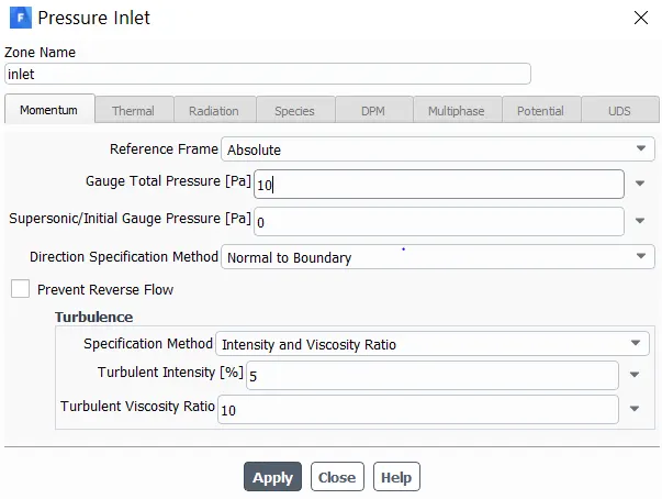
Boundaries:
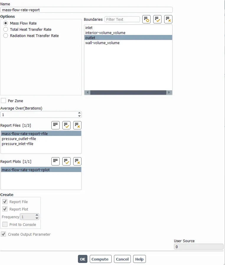
- Create a mass flow rate report :
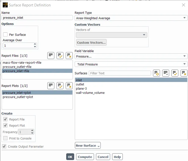
- Create a pressure at inlet report :
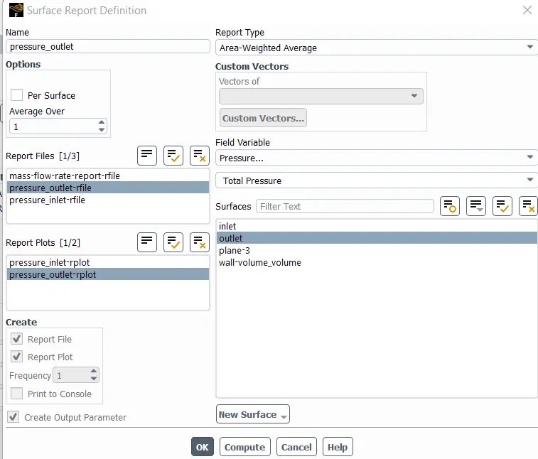
- Create a pressure at outlet report :
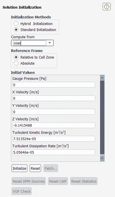
Initialization:
The standard method is selected and the initialization is done by selecting it from the inlet of the pipe.
Results:
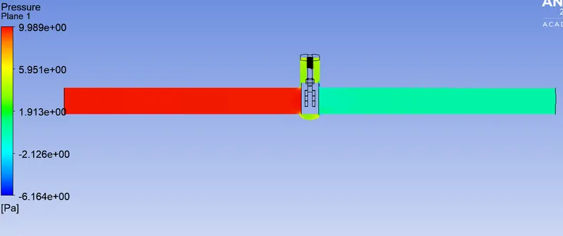
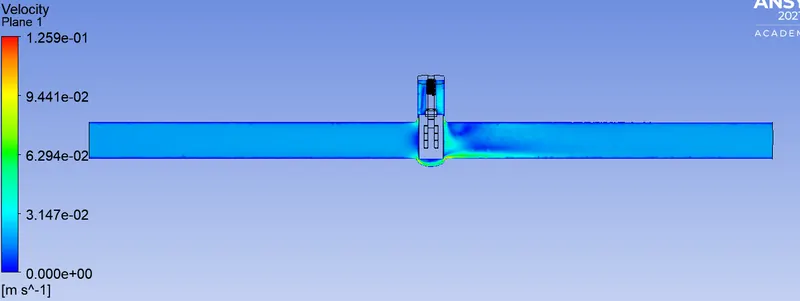
1.The following results were obtained with 10mm open.
Geometry:
Mesh:


Pressure Contour:
Velocity Contour:
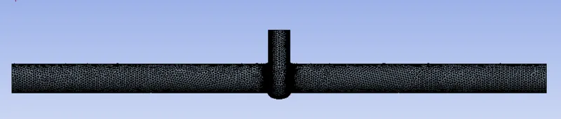
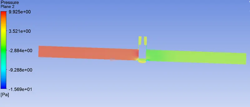
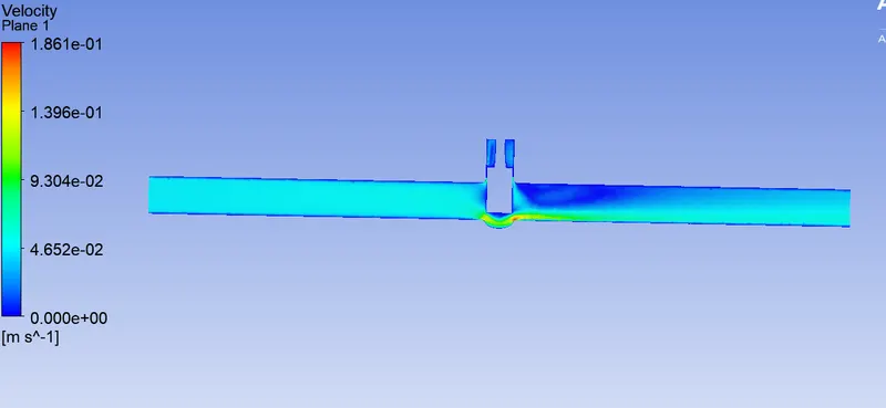
2.The following results were obtained with 30mm open.
Geometry:
Mesh:

Pressure Contour:
Velocity Contour:
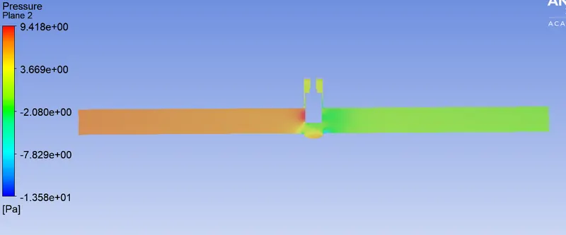
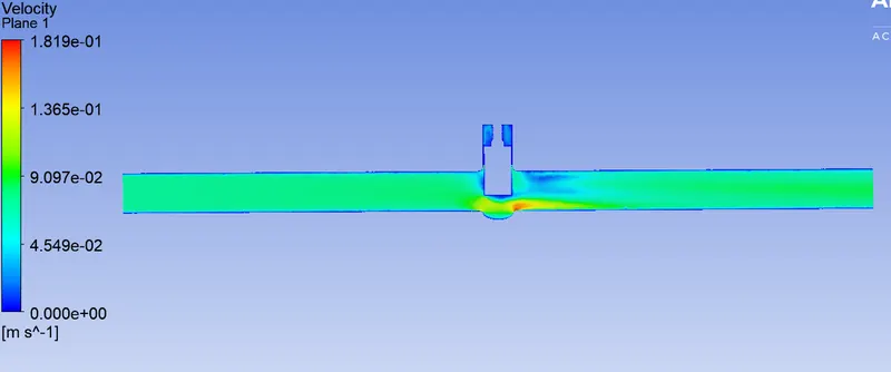
3.The following results were obtained with 50mm open.
Geometry:
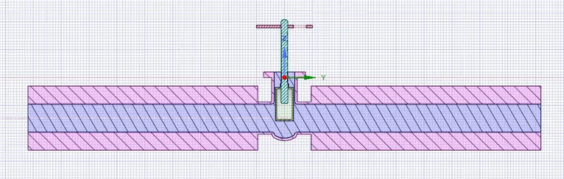
Mesh:
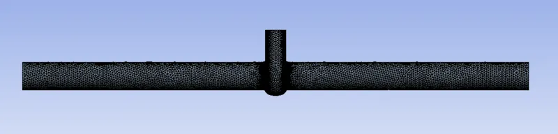

Pressure Contour:
Velocity Contour:
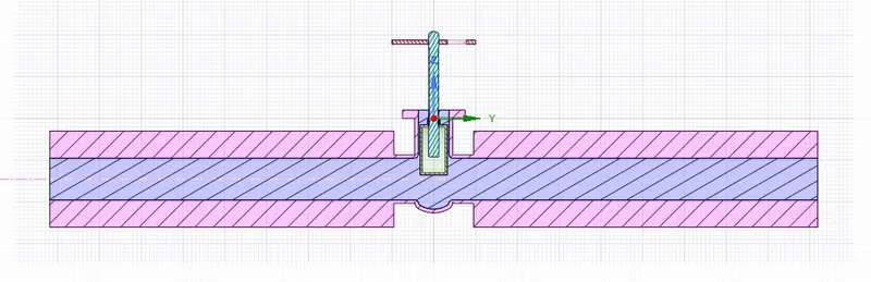
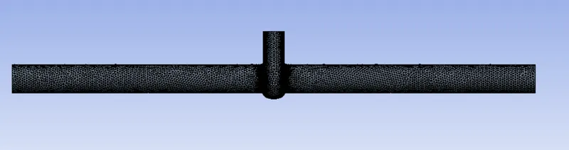
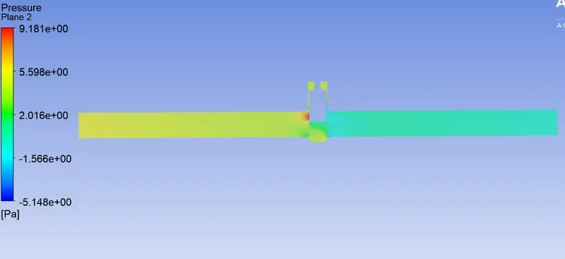
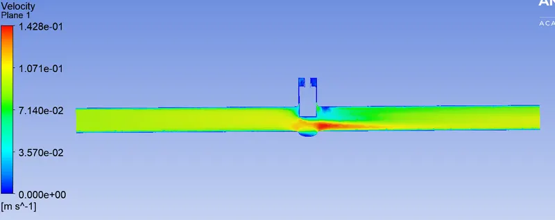
4.The following results were obtained with 70mm open.
Geometry:
Mesh:

Pressure Contour:
Velocity Contour:
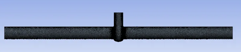
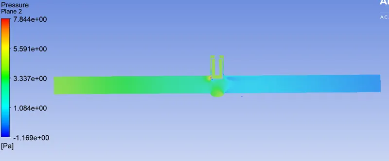
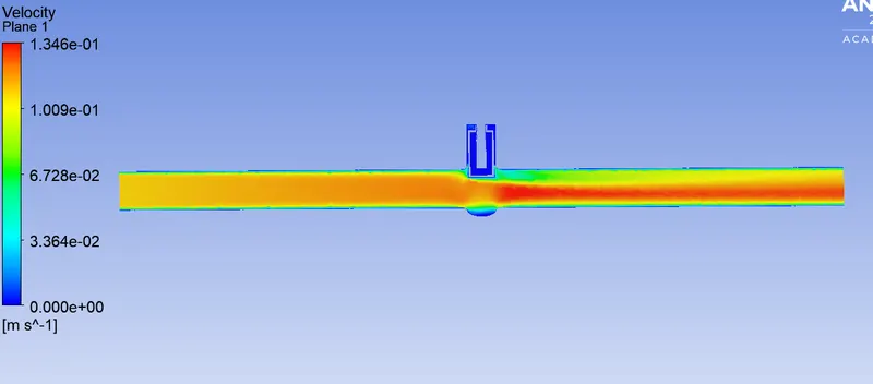
The following results were obtained with 90mm open.
Geometry:
Mesh:

Pressure Contour:
Velocity Contour:
Conclusion:
The following table was obtained from the parametric study.
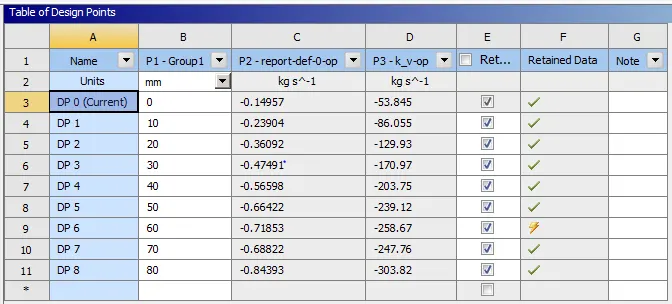
The mass flow rate at each opening of the valve are available in the parametric study table.
Graph between opening of the valve in mm and flow co-efficient.
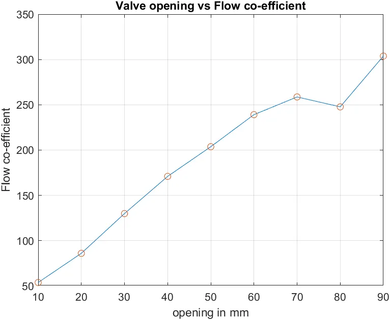
Smaller the valve opening, more the pressure loss and lesser the flow rate. We need to design the valve such that it has large value of the Flow co-efficient at operating conditions.
Conclusions:
1.Parametric studies allow you to nominate parameters for evaluation, define parameter ranges, specify design constraints, and analyze the results of each parameter variation. After the configurations are generated, you can evaluate your simulation. You can further refine the design parameters or constraints until you are satisfied with the results. Once you determine that the configuration meets your design needs, you can promote that configuration back into the model as a CAD modification. You will be asked if you want to make changes. Using the parametric study method saves a lot of time in simulations that require multiple executions of the same operations for different settings.
2.A parametric study requires the following:
- The design target is set to Parametric dimensions
- Parameters nominated for use in the simulation
- Parameter ranges identified
- Design criteria determined
- Various configurations generated
3.In a parametric study of a gate valve, it was found that as the valve stop is gradually raised, the mass flow rate of the fluid, and thus the flow factor and flow coefficient, increase.