Hood components mesh
AIM: The aim of this challenge is to carry out the necessary actions on the given model using ANSA to check the geometry, defeature, and generate a smooth mesh as per the mentioned quality criteria.
PROCEDURE:
- The given model was divided into 5 different PIDs. The first step was to check each part for correct orientation and geometry errors.
- To orient the model correctly, the Faces-Orient-Visible command was used.
- Once the model was correctly oriented, Checks-Geometry-Execute was used. The errors were rectified through manual and auto fix method(single con, triple con, needle face).
- Once the model was error-free, mid surface was generated using Faces-Offset-Feature Area and the center line of the surface was selected(Cross Hatches enabled) and the offset distance was entered based on the parent part thickness. This method was used because it was the most suitable method for extracting a mid surface from a complex geometry.
- Each mid surface was assigned a new PID using Faces-Set PID.
- After assigning the PID to the mid surface, the thickness of the parent part was entered into their respective property card. The components were then prepared for meshing, under the mesh deck.
- The length of the elements was assigned using Perimeters-Length-5. Defeaturing was carrying out on each component, where any feature which would fail to satisfy the minimum length criteria of the mesh was hidden using, Faces-cut command, and important features such as fillets were retained. Even number of edges was captured for all the holes.
- Once defeaturing was completed, all hot points were deleted and the mesh quality parameters were entered into Quality Criteria and Mesh Parameters.
- The component was then divided into smaller sections to generate a clean mesh using Macros- Cut.
- Once the model was cut into smaller regions, meshing was carried out on each region using Mesh Generation-Best/ Mesh Generation-Map.
- To obtain a clean mesh flow, operations such as Reconstruct and Smooth were used.
- In areas where there were opposite trias or rotating quads, the Split/Paste option was used, followed by Smooth, and tria elements were eliminated.
- The mesh flow errors were visible in the hidden view, where the total number of Off elements were displayed, that is the elements that are not in compliance with the mentioned quality criteria.
- Each error was rectified and a smooth, error-free mesh flow was obtained.
INITIAL MODEL:
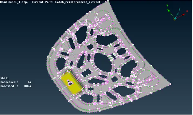
ORIENT OPERATION:
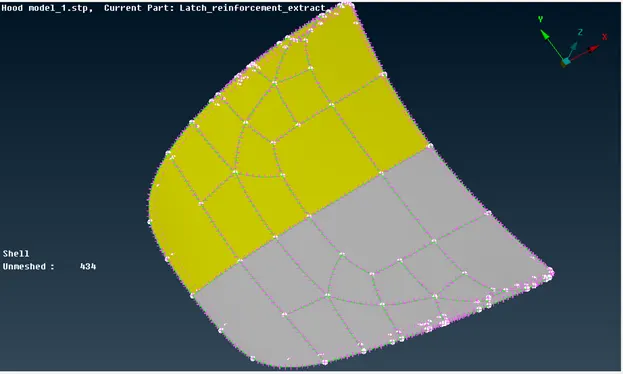
The image shows the incorrect orientation of the part.
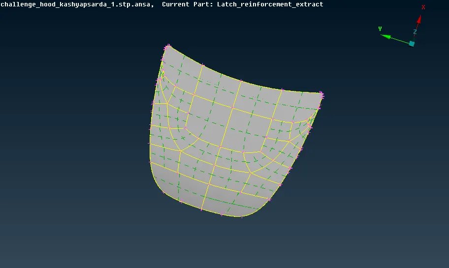
The image shows correct orientation, obtained after Orient operation.
DEFEATURING USING MACROS-CUT COMMAND:
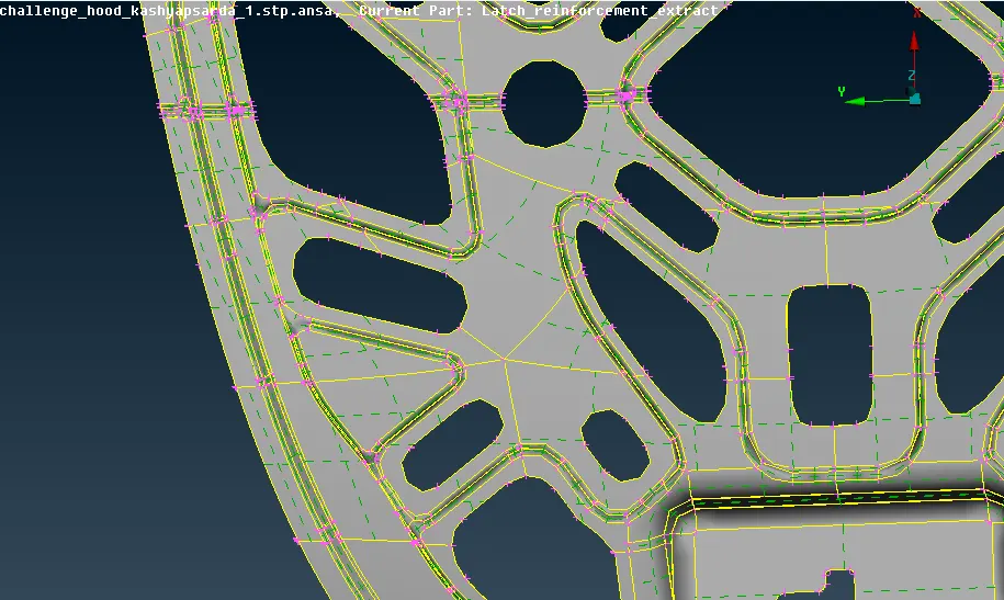
The image shows the unnecessary cons present in the model.
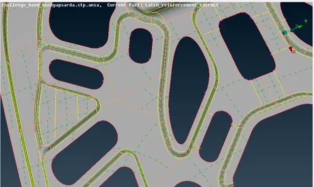
The image shows all the unnecessary cons hidden using Macros-Cut.
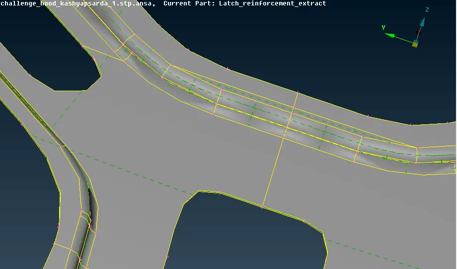
The image shows the model before defeaturing.
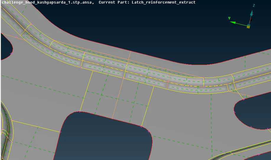
The image shows the model after defeaturing using Macros-Cut command.
TRIA NODE ELIMINATED USING SPLIT AND SMOOTH COMMAND:
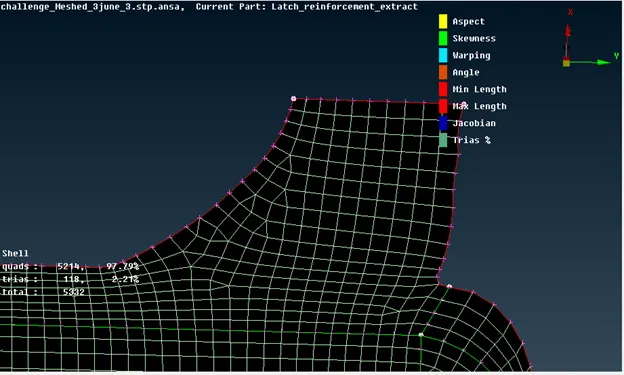
The image shows a tria element in the mesh that can be removed.
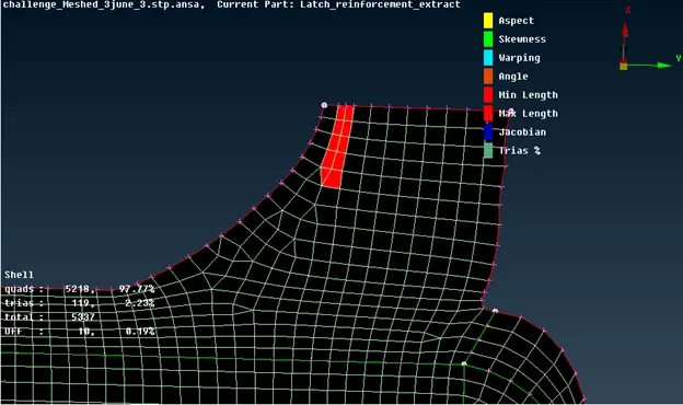
The image shows the Split operation carried out on the tria element.
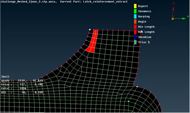
The image shows the tria element removed but incorrect mesh flow.
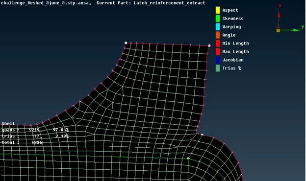
The image shows the error-free mesh flow after Smooth operation.
OPPOSITE TRIAS ELIMINATED USING PASTE, SPLIT AND SMOOTH:
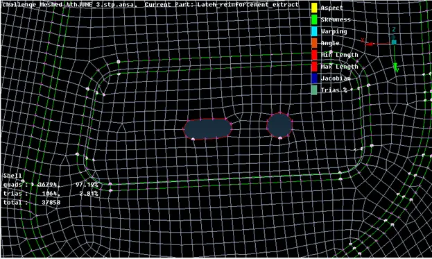
The image shows the opposite facing tria present in the mesh.
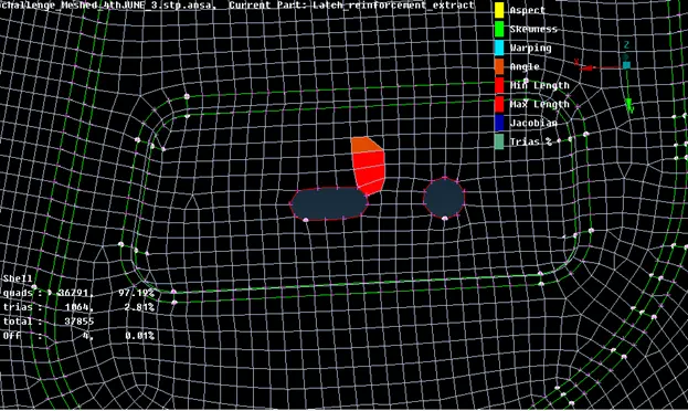
The image shows Paste operation carried out on one tria element.
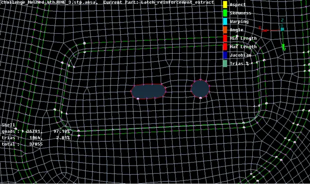
The image shows Smooth operation carried out to generate clean mesh flow.
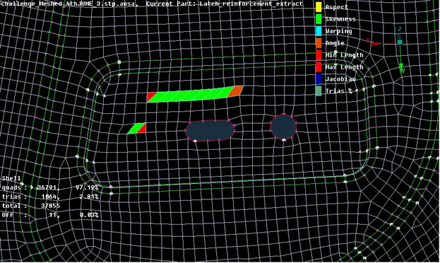
The image shows Swap operation carried out on one tria element in order to align with the other tria element.
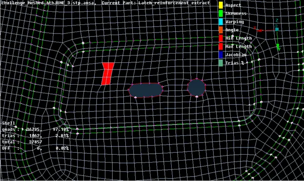
The image shows the mesh generated after eliminating the opposite facing tria elements using the Elements-SPlit command.
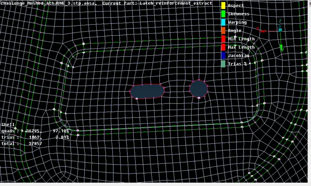
The image shows a smooth mesh generated after the Smooth command.
GENERATED MESH FLOW:
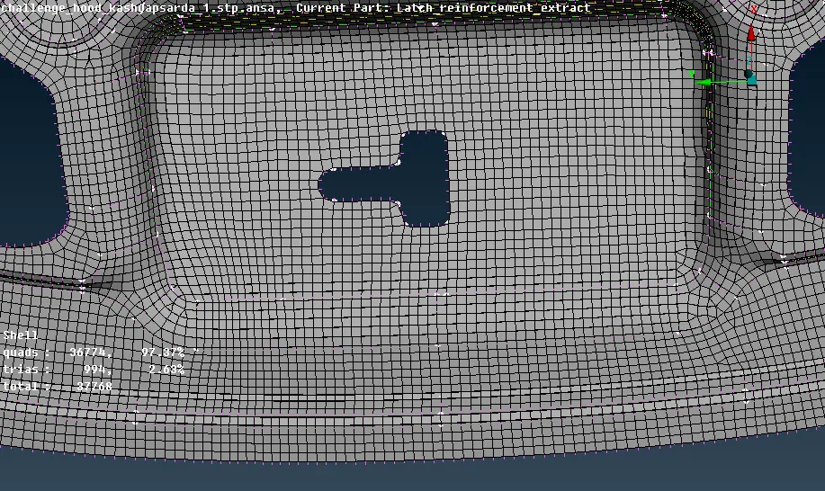
DRAW SHELL AS SOLID:
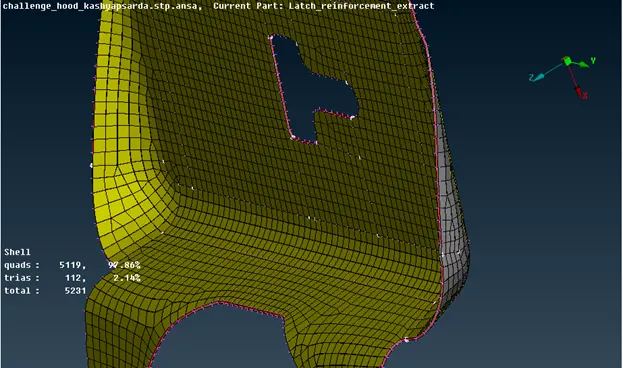
The image shows the shell mesh as solid.
LEARNING OUTCOMES:
Through this challenge, I learned how to:-
- Understand and use the Topo and Mesh deck of ANSA
- Carry out geometry clean up on a CAD model
- Generate a mid surface and assign property and material card to the part
- Identify the key features and defeature where ever the element length does not satisfy the mesh criteria and where extra cons have been generated because of converting from one format to another.
- Generate a mesh based on the required mesh criteria and parameters
- Eliminate tria, rotating quad elements
- Avoid tria elements near fillet areas
- Eliminate the number of Off elements
CONCLUSION:
Through this challenge, I was able to understand the scrutiny which went into meshing a component based on industry standards and how each element in the mesh flow can impact the analysis results. I learned the need to generate a mesh flow with the least possible triangular element percentage, and to avoid rotating quads and opposite tria elements.