Door switch bezel design and draft analysis
AIM: The aim of this project is to create a tooling axis for the given part and to make it a solid body of prescribed thickness.
PROCEDURE:
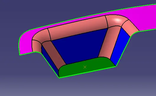
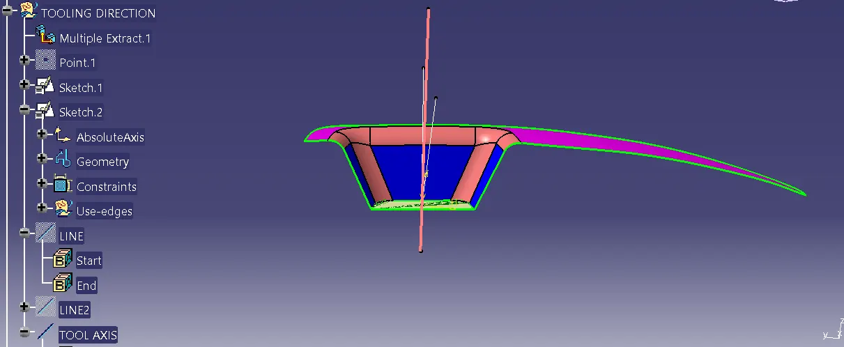
1. The first step was to create a tooling axis for the given surface model. The tooling axis helps determine the direction along which the mould will open. First, a point was created on the center of the surface(highlighted in green) and the two opposite surfaces(highlighted in blue) were used as a reference and a line was created which bisected the two surfaces. This line was again bisected using the third face and a tooling axis was created.
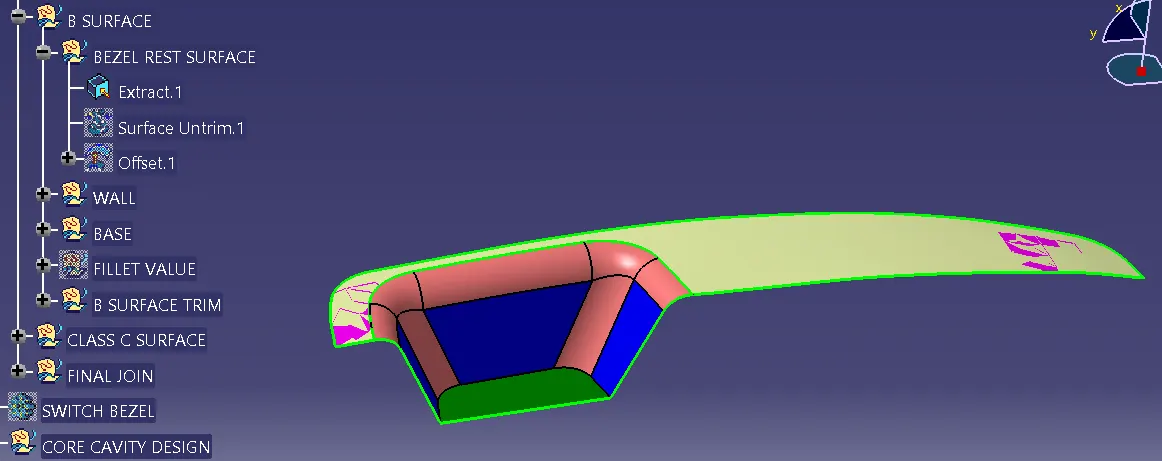
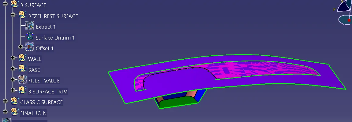
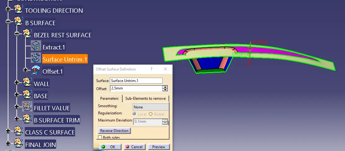
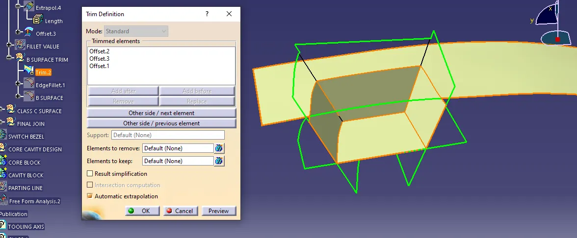
2. The second step was to create a solid part having 2.5mm thickness from the given A surface, i.e the B and C surface had to be constructed. The B surface was constructed by extracting all the flat faces on the A surface. Once all the faces were extracted, untrimmed, extrapolated, and were trimmed to give a surface similar to that of the A surface. The surface was then offset by 2.5 mm in the direction where B surface was needed.
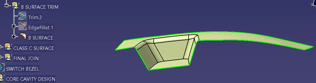
3. The next step was to add fillets to the B surface. In order to this, the fillets on the A surface were extracted and untrimmed and were measured using the Measure Item tool. Once the fillet values were known, it was possible to add them to the B surface.
4. In order to construct the C surface, a boundary was created using the Boundary tool and the A surface was used as a reference. A surface was created using the Sweep tool-draft option, and the tooling axis was selected as the draft direction and a draft angle of 3 degrees was given. The A surface was extrapolated by 2 mm using point propagation and all three surfaces were trimmed in order to obtain the final part body.
5. Draft analysis was carried out on the final body by inserting a Feature draft analysis. It was important that the part body was in customize view with material mode on. The first step was to turn on the compass option and to drag the compass and place it on the tooling direction in the correct orientation. Once it was placed, it has to be locked in that position. Then an 'x' cursor appears as we hover over the body and by clicking on it, the draft analysis is shown. The color code was red - negative, blue 0-3 degrees, and green above 3 degrees. Three degrees were chosen since it is the ideal draft angle for plastic components. The body was green which meant that it was a good design and that it would not cause any problems when the part is being extracted from the mould.
A SURFACE:
TOOLING AXIS CREATION:
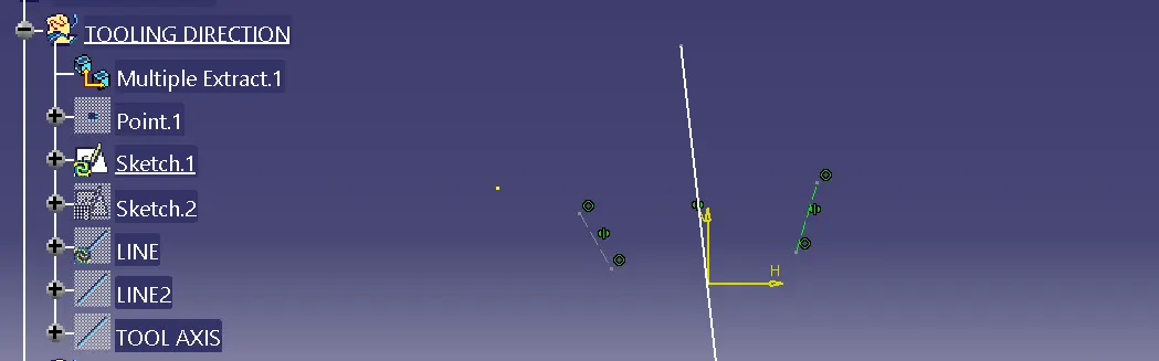
LINE 1 CREATED USING THE TWO OPPOSITE SURFACES
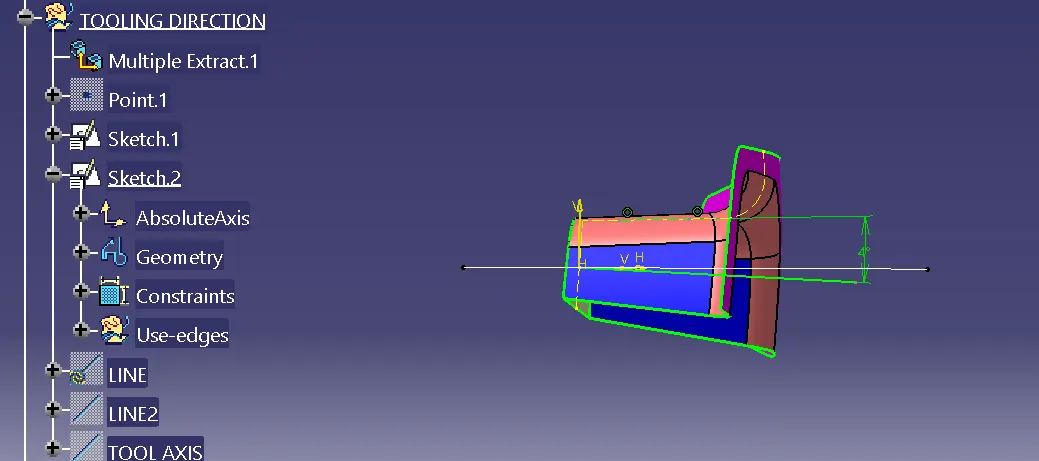
LINE 2 CREATED AT AN ANGLE OF 4 DEGREE TO THE SINGLE SURFACE
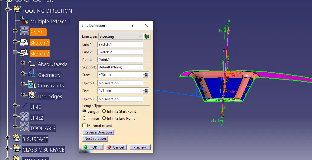
TOOLING AXIS CREATED BY BISECTING THE TWO LINES
CREATION OF B SURFACE:
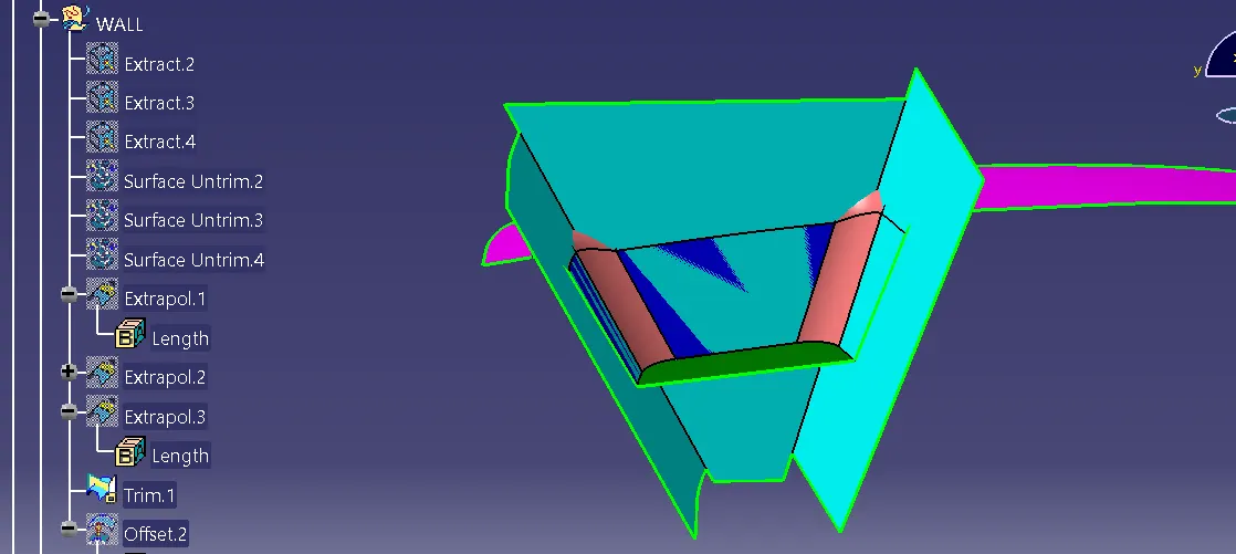
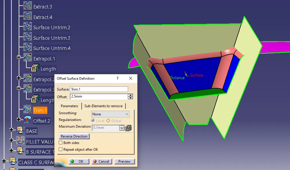
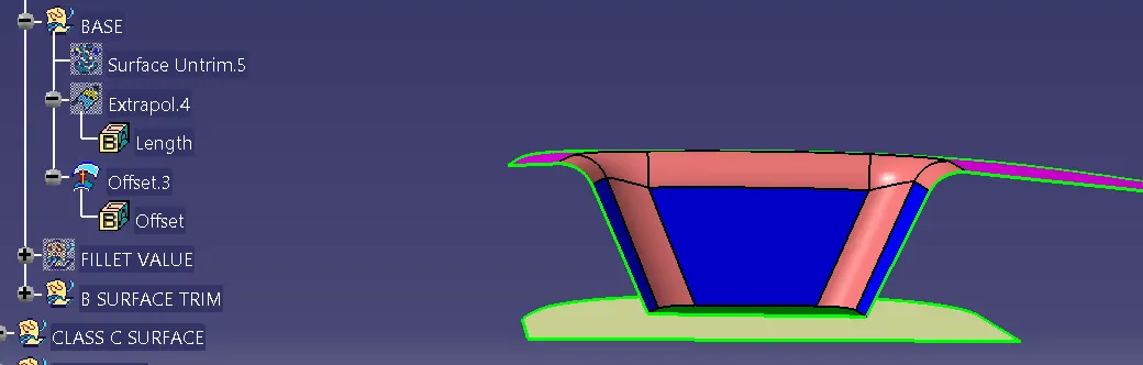
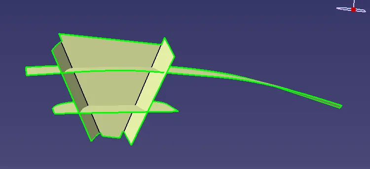
FINAL TRIM OF B SURFACE
ADDING FILLETS TO THE B SURFACE:
CREATION OF C SURFACE:
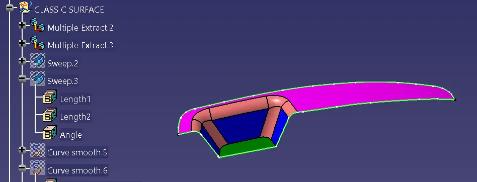
BOUNDARY CREATED AROUND A SURFACE, USING BOUNDARY TOOL
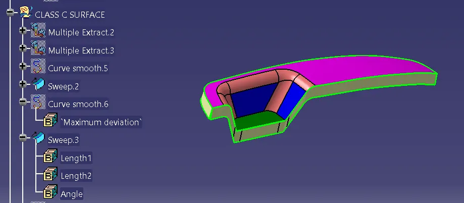
C SURFACE CREATED USING SWEEP WITH DRAFT DIRECTION AS TOOLING AXIS AND AT AN ANGLE OF 3 DEGREES
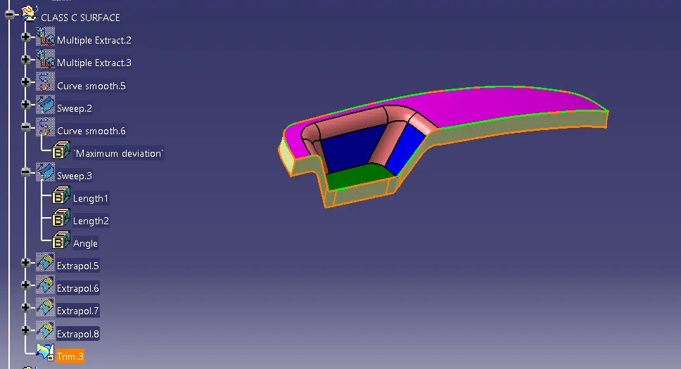
FINAL TRIM TO CREATE SURFACE BODY
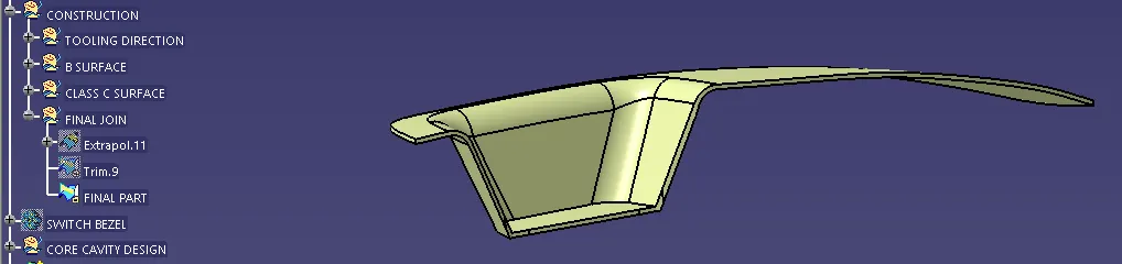
SOLID BODY CREATION:

SOLID PART BODY WAS MADE IN PART DESIGN WORK BENCH USING THE CLOSE SURFACE COMMAND
DRAFT ANALYSIS OF SOLID BODY:
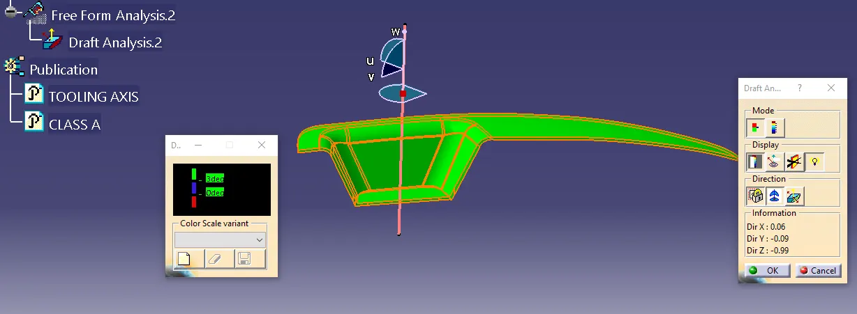
DRAFT ANALYSIS WAS DONE ON THE PART BODY TO SEE HOW THE PART WOULD INTERACT WITH THE MOULD AND TO JUDGE THE FEASIBILITY OF THE PART DESIGN