Stateflow Simulink
Stateflow: Simulink provides a design environment for developing state diagrams and flow charts. it is useful for applications involving logic, task scheduling, mode logic, etc. States, junctions, functions can be added from the graphical palette to the design environment. They are connected to one another with transitions which can contain transition conditions. This allows us to quickly build a state machine. During the simulation, which code or block is being run will be highlighted giving the programmer a better idea of how the logic is performing.
1)
AIM: The aim of this challenge is to program a control logic using Simulink Stateflow for the different running conditions of a washing machine.
OBJECTIVE:
The objective of this challenge is to simulate the working of a washing machine using Stateflow as per the given sequence:
- If the power supply is available, the system gets activated
- If the Water supply is not available, stop the process & indicate through LED
- Soaking time should be 200s followed by Washing time of 100s.
- Then rinsing happens for the next 20s & dryer runs for 50s
After all the processes have completed turn on the finished LED
CHART:
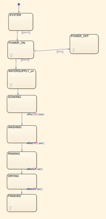
U defines the power supply and v defines the water supply state. If U=1, i.e the power supply is on, only then will the code move forward from the system block. Once power is on, using LAMP the POWER_ON block is highlighted as on. If the water supply is on, i.e V=1, then the solver moves forward from the POWER_ON block, if the water supply is off, then the code goes to POWER_OFF and it is highlighted by a red color lamp.
Since soaking was required to be carried out for 200seconds, after which washing will be carried out, after(200, sec) was defined as the transition condition.
OUTPUT:
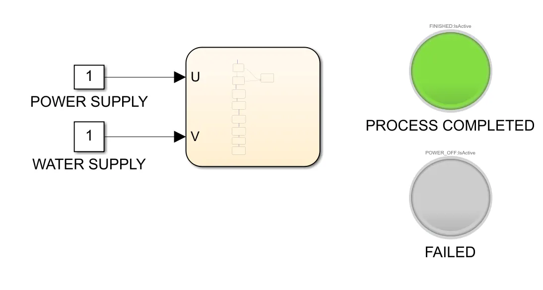
POWER: ON
WATER SUPPLY: ON
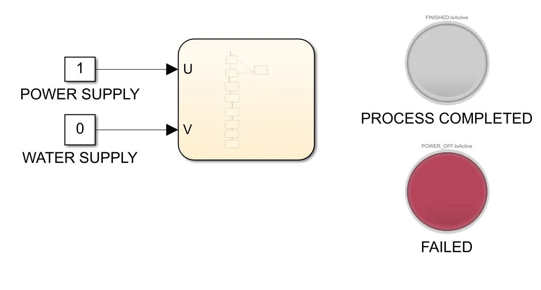
POWER: ON
WATER SUPPLY: OFF
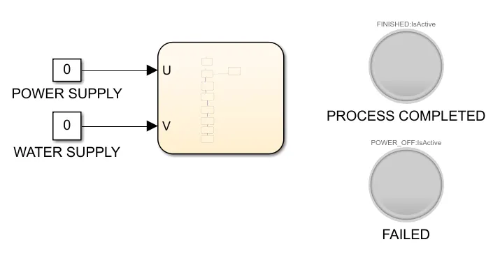
POWER: OFF
WATER SUPPLY: OFF
No display is shown since there is no power.
2)
AIM: The aim of this challenge is to program a control logic using Simulink chart of a car's transmission as per the given conditions.
OBJECTIVE:
The objective of this challenge is to make a Simulink chart for the “Gear shift” logic as per the below conditions:
Speed Range(kmph) Gear
0 to 15 1
16 to 25 2
26 to 40 3
41 to 60 4
Above 61 5
And to give the speed input while the simulation is running & display the gear number.
CODE:
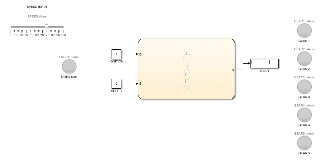
CHART:
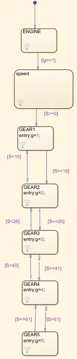
The speed input was given using a slider block, the same could be done using a knob block also. A constant block was given as input for ignition state and speed. The slider block was then connected to the speed constant block. In the chart, ig==1 was defined as the condition to move from the ENGINE block to speed block, that is the code would proceed ahead only if the ignition input condition was satisfied. S was used as a variable for speed and the speed conditions were defined for each gear. If S>=0, then gear 1 would be displayed in the display block and GEAR 1 lamp would be highlighted. If the speed were to cross 16kmph, then the code would move to the GEAR2 block. If the speed were to drop below 16Kmph, then the code would go back to GEAR1 block.
OUTPUT:
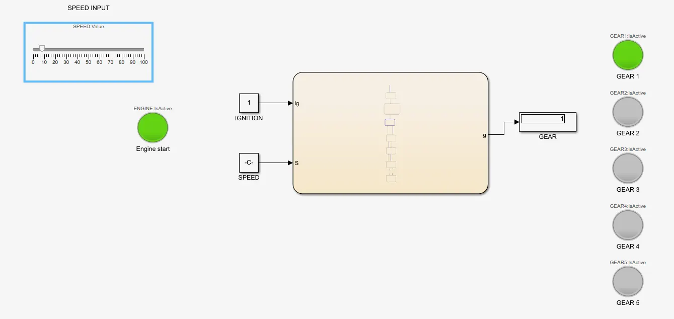
speed = 9kmph, gear 1 is highlighted
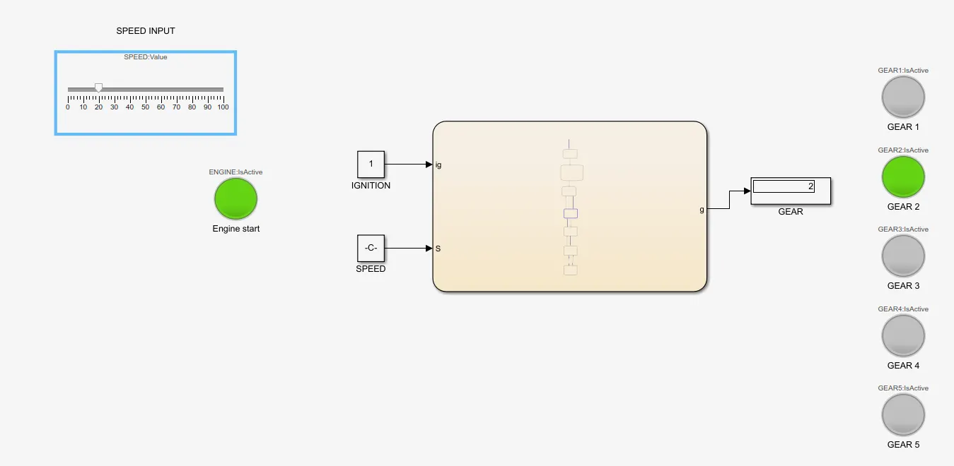
speed = 20kmph, gear 2 is highlighted
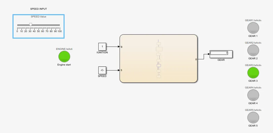
speed = 31kmph, gear 3 is highlighted
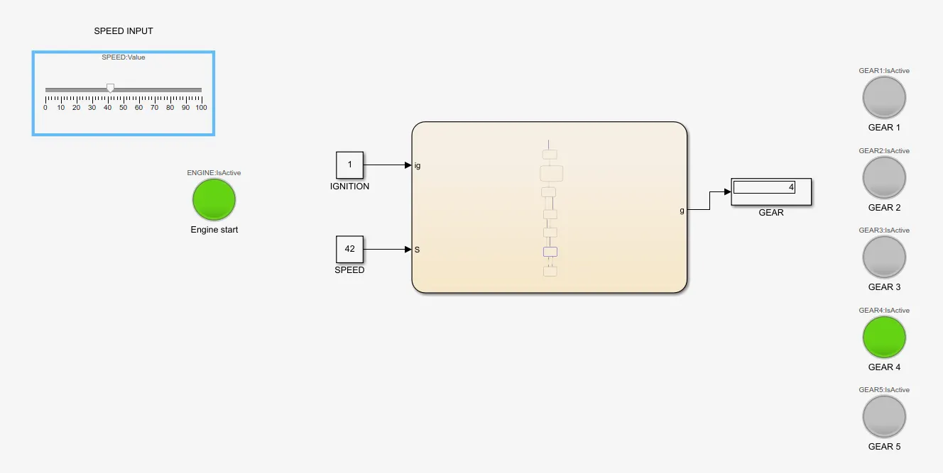
speed = 41kmph, gear 4 is highlighted
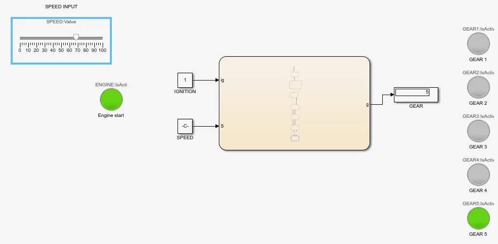
speed = 68kmph, gear 5 is highlighted