SIMULINK model of Door bell & thermistor.
PART 1
AIM: To make a Simulink model of Doorbell using solenoid block.
BODY:
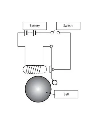
In the above arrangement, when the switch is closed the electromagnet receives electrical power from the battery and pulls the metal arm to hit the bell producing sound.
SIMULINK MODEL:
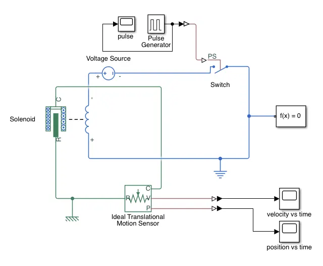
BLOCKS USED:
- Pulse generator
- Switch
- Voltage source
- Solenoid
- Mechanical reference
- Ideal translation motion sensor
- Electrical reference
- Solver configuration
- Scope
EXPLANATION:
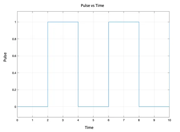
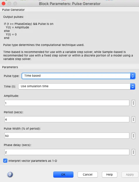
- Pulse generator is used to generate pulse at an interval of two seconds with a two second delay.
 .
. 
- The pulse tells the switch when to open and when to close.
- Voltage source provides the needed voltage for the working of bell.
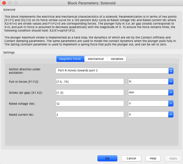
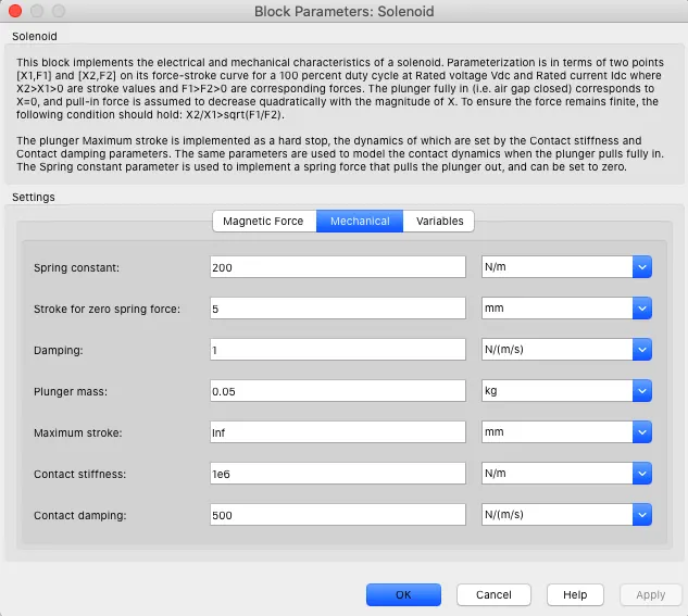
- Solenoid gets the current from the voltage source and generated temporary magnetic field which moves the plunger thereby making the plunger to strike the bell.
- Ideal motion sensor measures the movement characteristics of the solenoid.
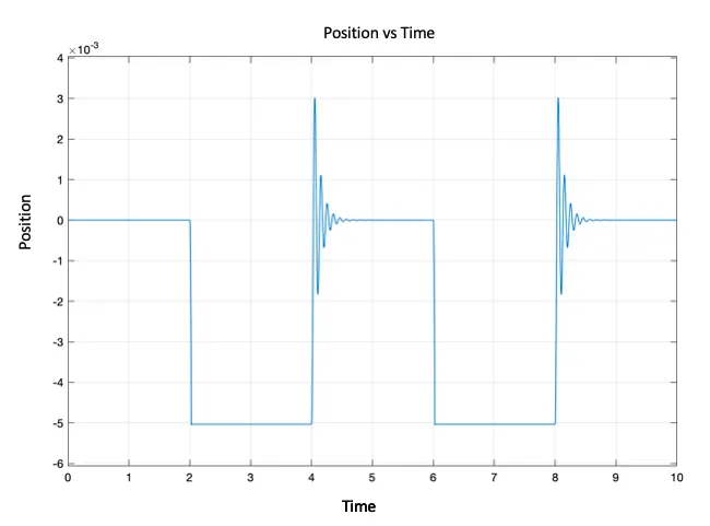
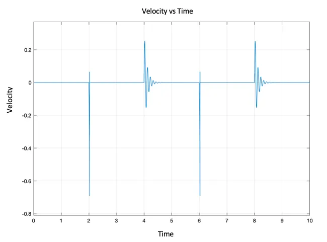
- Scope provides the graphs such as position vs time and velocity vs time of the metal arm of the striker.
RESULTS:
 .
. 
PART 2
AIM: Use a thermistor to sense the temperature of a heater & turn on or turn off the fan.
BODY:
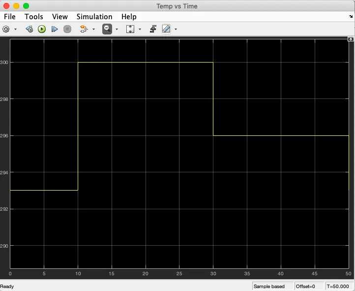
Temperature source: 20 °C from 0 to 10 seconds, 27 °C from 10 to 30 seconds, 23 °C from 30 to 50 seconds
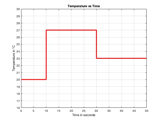
Condition to turn on the fan: if the temperature is above 25 °C.
General working:
A thermistor is a resistance thermometer, or a resistor whose resistance is dependent on temperature. The term is a combination of “thermal” and “resistor”. It is made of metallic oxides, pressed into a bead, disk, or cylindrical shape and then encapsulated with an impermeable material such as epoxy or glass.Thermistors are easy to use, inexpensive, sturdy, and respond predictably to changes in temperature. While they do not work well with excessively hot or cold temperatures, they are the sensor of choice for applications that measure temperature at a desired base point. They are ideal when very precise temperatures are required.
SIMULINK MODEL:
BLOCKS USED:
- Repeating Sequence Stair
- Scope
- Controlled Temperature Source
- Thermistor
- Resistor
- Voltage source
- Electrical reference
- Voltage sensor
- Simulink-PS convertor
- PS-Simulink convertor
- Display
- Switch
- Constants
- DC motor
- Ideal Rotational Motion Sensor
- Mechanical Rotational Reference
- Solver configuration
EXPLANATION:
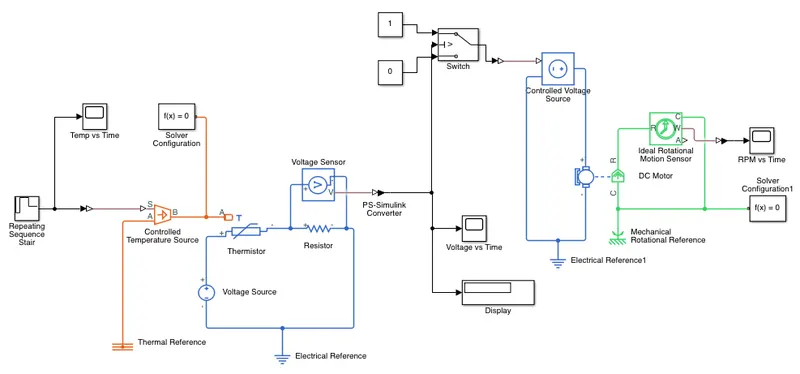
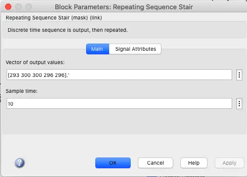
- Repeating sequence stair is used to make temperature signal.
- The temperature signal is fed into controlled temperature source.
- Thermistor sense the change in temperature and changes the resistance accordingly.
- Voltage sensor measures the voltage for particular resistance which in a way gives voltage for particular value of temperature. Since the resistance changes with temperature.
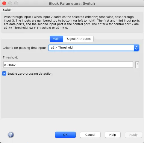
- Since the fan is supposed to turn on when the temperature is 298 K or above, the value of voltage corresponding to temp 298 K is given to the switch as threshold value.
- The switch turns on when the voltage reaches its threshold value.
- This turns on the DC motor (Fan).
 .
. 
RESULT:
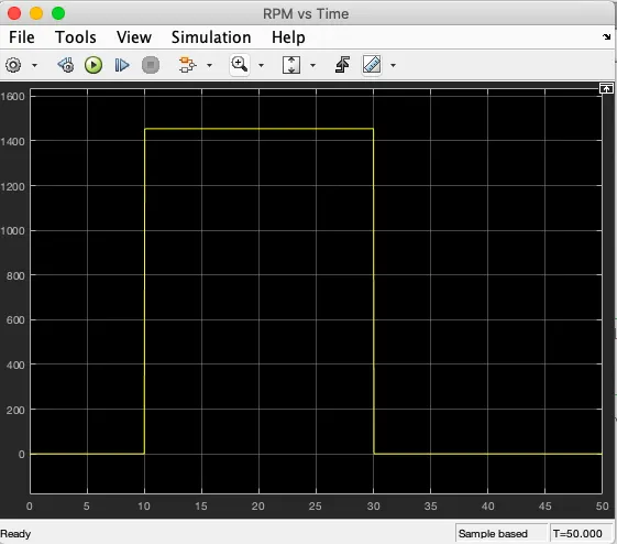
As we can see the fan (dc motor) is turned on for 20 seconds between t = 10 sec to t = 30 sec when the temperature is more than 298 K or 25 °C.