Project-1: Modelling an electric Car with Li-ion battery
AIM: To create a MATLAB model of the electric car.
OBJECTIVE:
- To implement vehicle control using a PI controller.
- To generate brake and acceleration commands.
- To use a lithium-ion battery pack.
- To choose a suitable motor.
BODY:
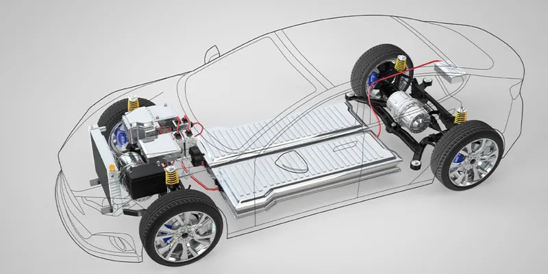
An electric vehicle is a vehicle that uses the battery as a power source and uses electric motors for the propulsion of the vehicle. The electricity is stored in the battery and it is used to power the electric motors and the battery can be recharged.
SIMULINK MODEL:
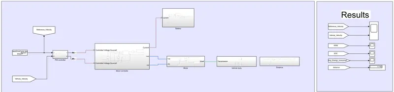
SUB SYSTEMS:
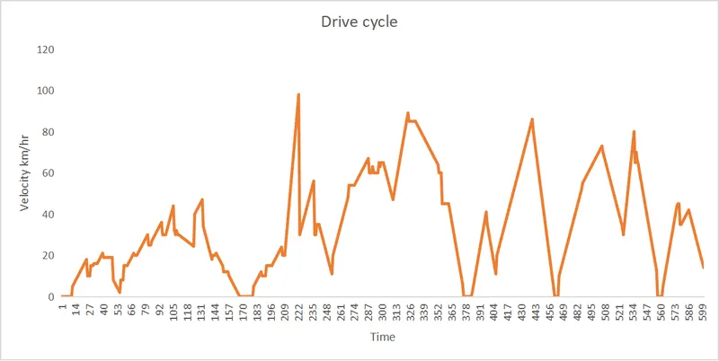
a. Drive cycle
Block- From spreadsheet
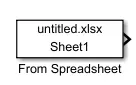
Using this block we can add a custom drive cycle into the simulation.
Parameters
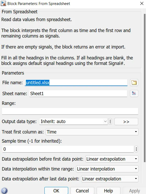
input
b. PID controller
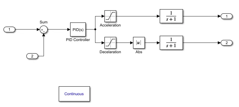
Block - PID

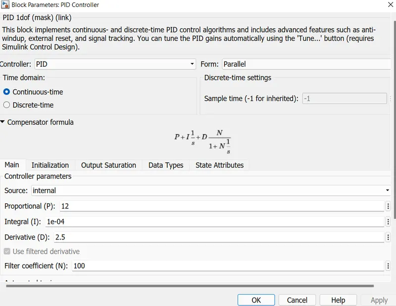
- Proportional integral derivative (PID) controllers can be attributed partly to the wide range of operating conditions and partly to the functional simplicity.
- PROPORTIONAL RESPONSE: The proportional component depends only on the difference between the setpoint and the process variable. The proportional gain K_c determines the ratio of the output response to the error signal.
- INTEGRAL RESPONSE: The integral component sums the error term over time. The result is that even a small error term will cause the integral component to increase slowly. The integral response will continuously increase over time unless the error is zero, so the effect is to drive the steady-state error to zero.
- DERIVATIVE RESPONSE: The derivative component causes the output to decrease if the process variable is increasing rapidly. The derivative response is proportional to the rate of change of the process variable.
parameters
c. Motor controller
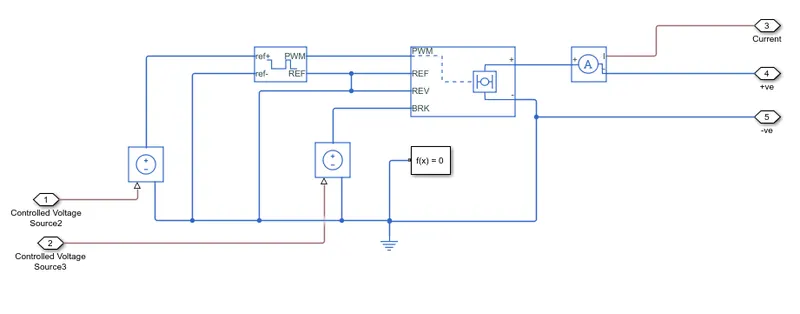
Block - controlled PWM voltage
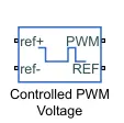
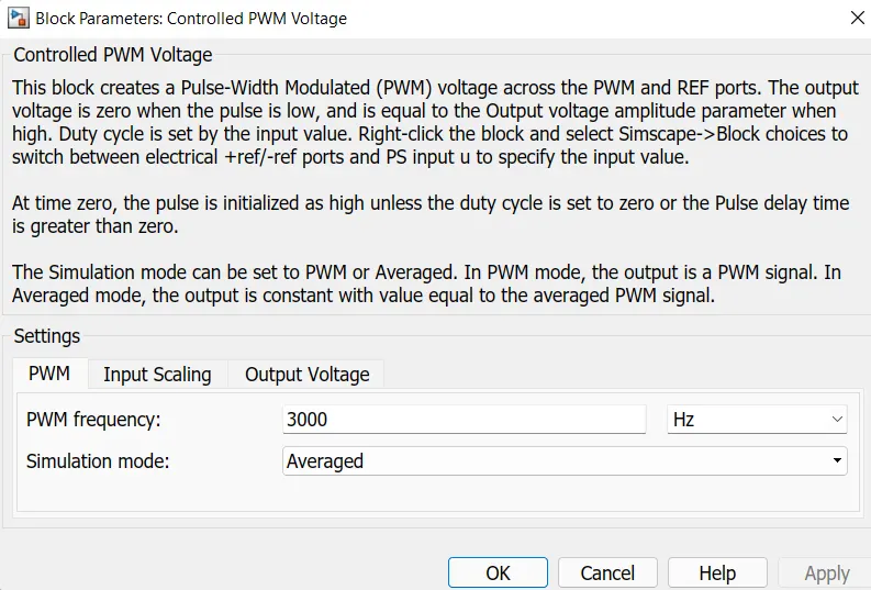
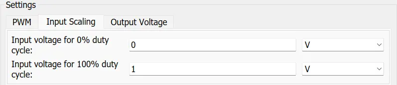
This Block will create a Pulse width modulation (PWM) signal across the PWM and REF ports. The output voltage is zero when the pulse is low and equal to the output voltage amplitude parameter when high. At time zero the pulse is initialized as high unless the duty cycle is set to zero or the pulse delay time is greater than zero. The simulation mode is chosen as averaged where the output signal will be constant with a value equal to the averaged PWM signal.
Parameters
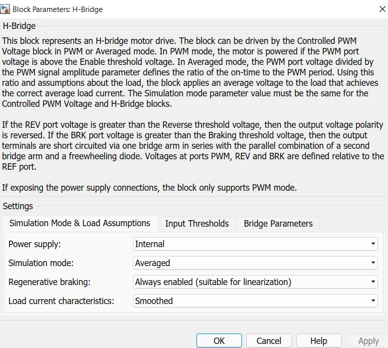
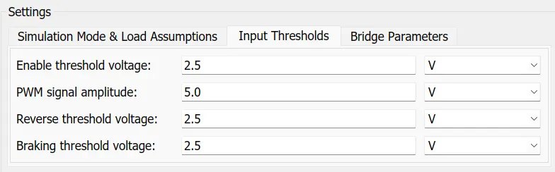
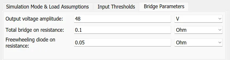
Block - H-bridge
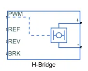
H-bridge is an electronic circuit that enables to apply voltage to load in either direction. It is commonly used to control DC motors. By using H-bridge the DC motor can be used to run in clockwise and in anti-clockwise directions. This block is also used to produce alternating waveforms. For averaged simulation mode the load current characteristics are set to smooth rather than discontinuous.
parameters
d. Battery
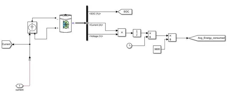
Block- battery
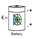
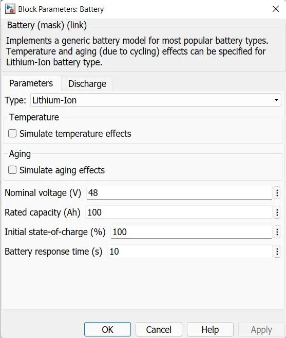
The internal resistance is assumed to be constant during the charge and discharge cycles and does not vary with the amplitude of the current. The discharging and charging characteristics are assumed to be the same. The capacity of the battery does not change with the amplitude of the current. When the battery gets charged then there is an exponential voltage drop and the width of the drop is depends upon the battery type. The positive terminal of the battery is connected to the controlled current source block where the current is controlled as per the voltage of the DC motor.
parameters
e. Motor
Block- DC motor
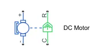
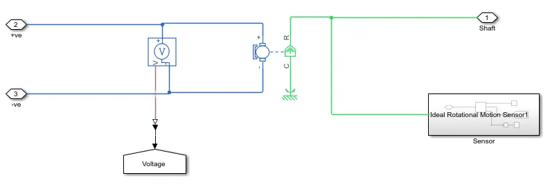
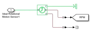
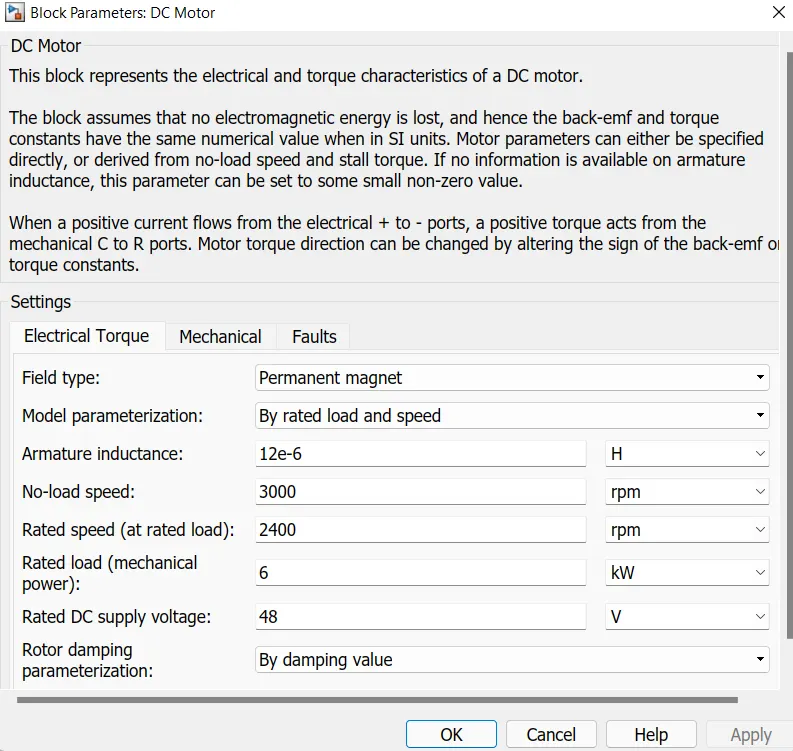
This block constitutes both the electrical and torque characteristics of the DC motor. There will no electromagnetic energy is lost, and hence the back-emf and torque constants have the same numerical value in SI units. The type of motor chosen is the permanent magnet type so it resembles the BLDC type of motor which is commonly used in electric vehicles.
Parameters
f. Vehicle body
Block - Vehicle body
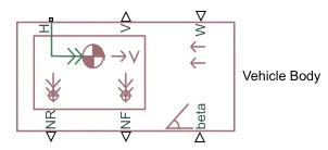
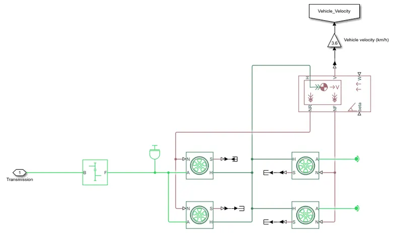
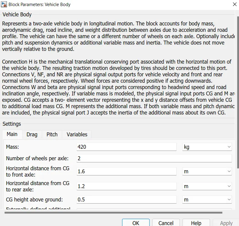
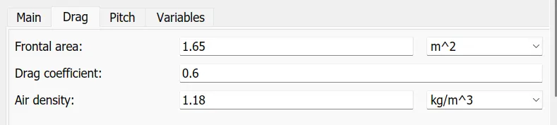
This block represents a two-axle vehicle body in longitudinal motion. The block accounts for body mass, aerodynamic drag, road incline and weight distribution between axles due to acceleration and road profile. This block gives the option of having the same or a different number of wheels on each axle with the optional inclusion of pitch and suspension dynamics or additional variable mass and inertia. This block consists of a total of 6 connection ports, out of which H is the mechanical translational conserving port associated with the horizontal motion of the vehicle body and it's connected to the H port of the wheel hub of the tire through which the resulting traction motion of the tires will get generated. V is the physical output port that is used to examine and monitor the vehicle velocity curve, NF and NR are also physical output ports but they represent front and rear normal wheel forces and due to this reason they are connected to the N of the tires through the forces will get active on the wheel for rotation. W and beta are physical signal input ports corresponding to headwind speed and road inclination angle.
Parameters
Block - tire
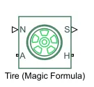
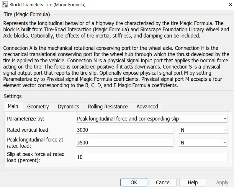
The tire magic formula block can model tire dynamics under constant or variable pavement conditions. The longitudinal direction of the tire is the same as its direction of motion as it rolls on pavement and to increase the fidelity of the tire model, the properties can be specified such as tire compliance, inertia and rolling resistance.
Parameters
Block - simple gear
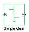
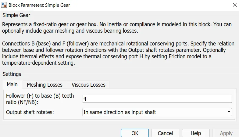
This block represents a fixed ratio gear or gearbox. No inertia of compliance is modelled in this block. Connections B(base) and F(follower) are mechanical rotational conserving ports that are connected to the shaft input of the DC motor and the A port of the wheel and axle.
Parameters
g. distance
RESULTS:
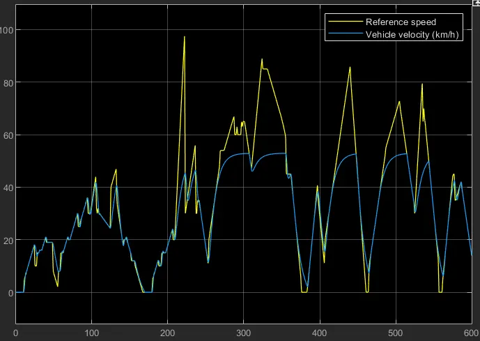
a. Velocity
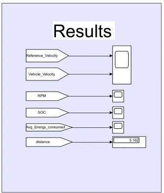
The PID controller is trying to adjust according to the reference speed.
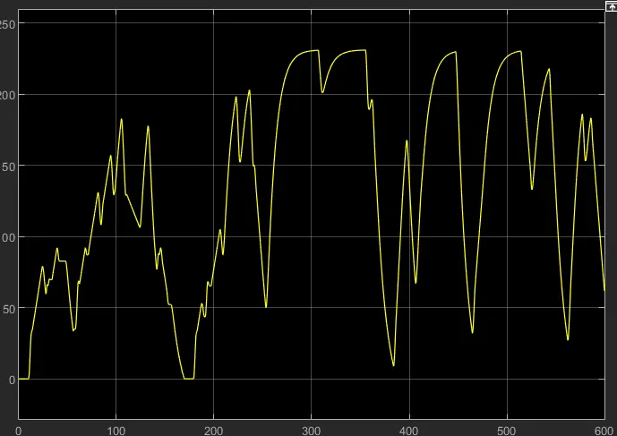
b. RPM
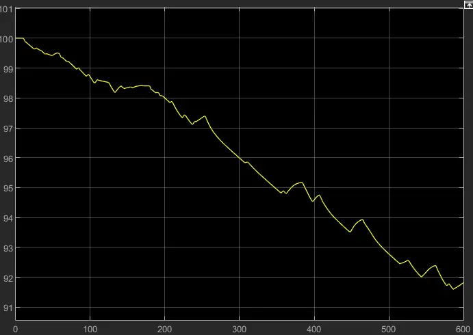
c. SOC
As we can see there is a drop in the % charge of about 8% in the battery and also for some time there is also charging of the battery due to regenerative braking.
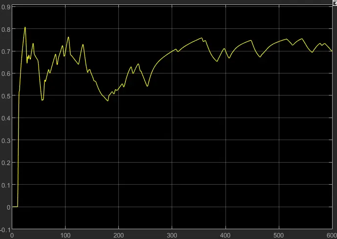
d. Average energy consumed.
e. Distance traveled.
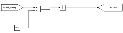
After travelling for about 600 seconds the vehicle has covered 5.162 km.

CONCLUSION:
As we can see by using the blocks present inside the Simulink library, an EV vehicle can be modelled efficiently and can be tested for different drive cycles, by considering various parameters accordingly.