MATLAB program to simulate 2R Robotic arm.
AIM: To write a program to simulate 2R Robotic arm
GOVERNING EQUATIONS:
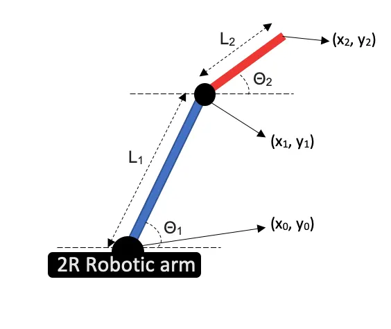
Figure 1
x1 = x0+ L1 * cos(Θ1) / Calculates X co-ordinate of the end point of link 1
y1 = y0+ L1 * sin(Θ1) / Calculates Y co-ordinate of the end point of link 1
x2 = x1+ L2 * cos(Θ2) / Calculates X co-ordinate of the end point of link 2
y2 = y1+ L2 * sin(Θ2) / Calculates Y co-ordinate of the end point of link 2
OBJECTIVE: To simulate the movement of 2R robotic arm and produce a video file showing the same.
BODY:
The end points of the link1 at any instant can be calculated easily with the help of co-ordinates of the base and the angle made by the link1 with the horizontal axis.
The end points of the link2 can be calculate similarly using the end co-ordinates of link1 and the angle made by the link2 with the horizontal axis.
Then these points for different angles can be used to plot the line and then the motion of links can be analyzed.
MATLAB code:
%foward kinematics with variable theta

clear all
close all
clc

%inputs

%counter
ct = 1;
%initial points
x0 = 0;
y0 = 0;
%length of first rod | m
l1 = 1;
%length of second rod| m
l2 = 0.5;
% angle made by first link with base | degrees
theta1 = linspace(0,90,10);
% angle made by second link with horizontal axis | degrees
theta2 = linspace(0,90,10);

for i = 1:length(theta1)
    THETA1 = theta1(i);
    for j = 1:length(theta2)
        THETA2 = theta2(j);

       % link 1 end points
       x1 = x0 + l1*cosd(THETA1);
       y1 = y0 + l1*sind(THETA1);
       % link 2 end points
       x2 = x1 + l2*cosd(THETA2);
       y2 = y1 + l2*sind(THETA2);

       % plotting

       plot([x0 x1],[y0 y1],[x1 x2],[y1 y2],'linewidth',10)
       pause(0.3)
       legend('link1','link2')
       axis([-0.1 1.5 0 1.5])
       % saving individual frames
       K(ct) = getframe(gcf);
       ct = ct+1;

    end
end
% making the video file
movie(K)
videofile = VideoWriter('foward_kinematics_variable.avi','uncompressed AVI');
open(videofile)
writeVideo(videofile,K)
close(videofile)
% end of the programExplanation:
Lines 9-21
It includes all the inputs
theta1 is an array with 10 values ranging from 0 to 90
theta2 is an array with 10 values ranging from 0 to 90
Lines 23-46
Contains nested for loops, every time the for loop runs Theta1 and Theata2 changes with each value of Theta1 there are 10 values of Theta2 so the total values come out to be 100.
Lines 35-40
And inside the nested for loop, plot command is used to plot lines and pause command is used to pause the display of individual graphs and axis command is used to fix the axis of the graphs.
Line 42
Each frame of the graph is saved in an array called ‘K’ with the help of getframe command.
Line 47-52
Video file is created with the frames saved in ‘K’
RESULT:
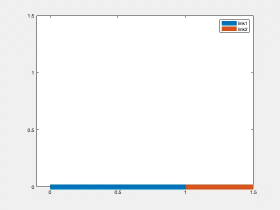
CONCLUSION:
The robotic arm has a wide application in the manufacturing domain, it is used to weld parts in the assembly line where hand wielding cannot be done or where there is risk involved or is used in the automatic paint booth hence it is very important to study the motion of robotic arm. The program deals with the simulation of 2R robotic arm the same process can be followed to simulate a robot with three arm or for different range of angles and arm lengths.