Week-7 Challenge: DC Motor Control
PART 1
AIM: To study MATLAB demo model ‘Speed control of a DC motor using BJT H-bridge’.
OBJECTIVE:
A. Study the working and comment on various results.
B. Comment on the armature current shoot-up from the scope results.
C. Compare it with ‘The Four-Quadrant Chopper DC Drive (DC7) block’.
part A
INTRODUCTION:
This model consists of an H bridge with 4 BJT-Diode Pair. The inputs such as duty cycle and step time are given from the 'Pulse Generator Block', 'Armature Voltage Control' Block.
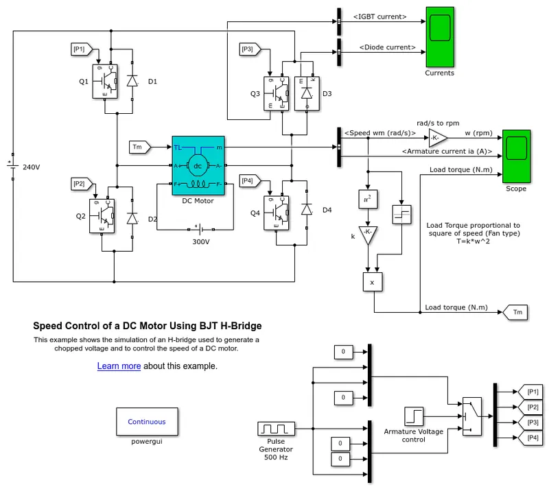
This H Bridge is made up of four switches Q1, Q2, Q3, Q4, and four diodes D1, D2, D3, D4. An IGBT can be used as a switch which can be either in off or on position. When the motor is coasting it generates electricity due to the flexibility of this
BODY:
Different Modes Available:
- If Switch Q1 and Q4 are closed, this will cause the current to flow from the source, through Switch 1 and then through the load, then through Switch Q4, then down to the ground. This is known as Forward motion of the motor.
- If Switch Q2 and Q3 are closed, this will cause the current to flow from the source, through Switch 3 and then through the load, then through Switch 2, then down to the ground. This is known as the Reverse motion of the motor.
- If Switch Q1, Q3, or Q2, Q4 is Closed, then both sides of the motor have no potential difference and this is called Brake mode.
- If Switch Q1, Q2, or Q3, Q4 is closed, then it will cause a short and burn out the H-bridge.
If only one switch or none are closed, in this state the motor will be just coasting.
Working of Model:
- The DC motor uses the pre-set model (5 HP 24V 1750 rpm). It simulates a fan-type load. The armature mean voltage can be varied from 0 to 240 V when the duty cycle (specified in the Pulse Generator block)is varied from 0 to 100%.
- The H-bridge consists of four BJT/Diode pairs (BJT simulated by IGBT models).
- Two transistors are switched simultaneously: Q1 and Q4 or Q2 and Q3. When Q1 and Q4 are fired, a positive voltage is applied to the motor, and diodes D2-D3 operate as free wheeling diodes when Q1 and Q4 are switched off.
- When Q2 and Q3 are fired, a negative voltage is applied to the motor, and diodes D1-D4 operate as free wheeling diodes when Q2 and Q3 are switched off.
RESULT:
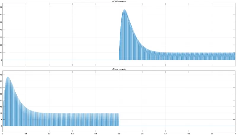
1. The graph shows the current passing through IGBT and Diode. So for 0 to 0.5-sec current is flowing through the diode D3 and 0.5 to 1 sec the current is passing through Q3.
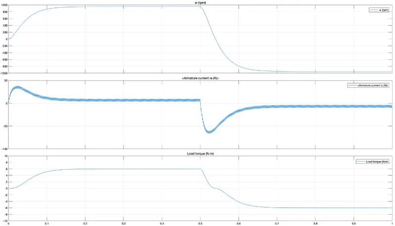
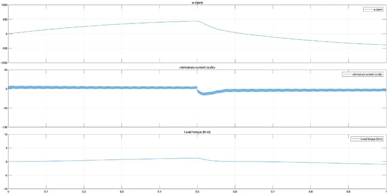
2. The plot shows that at the beginning of the cycle there is a sudden peak in armature current, the same repeats in the opposite direction when the motor rotates in opposite direction also Load torque is proportional to the square of angular velocity.
part B
The reason for the armature current shoot-up is -
As the principle of Pulse Width Modulation (PWM), the average value of Voltage (and Current) fed to the load is controlled by turning the switch between supply and load on and off at a fast rate. The PWM switching frequency has to be high enough not to affect the load, which is to say that the resultant waveform perceived by the load must be as smooth as possible. The peaks can be removed by reducing the duty cycle.
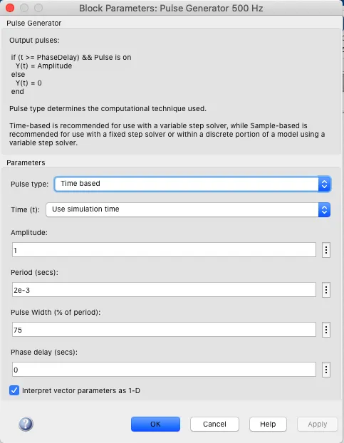
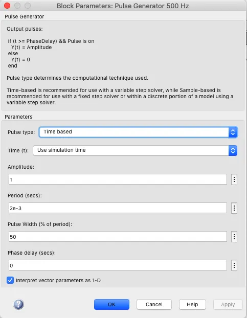
Here the pulse width is reduced to 50% from 75%.
RESULT:
As we can see the current shoot-up is reduced.
part C
Comparing 'The Four-Quadrant Chopper DC Drive (DC7) block' with ‘Speed control of a DC motor using BJT H-bridge’.
|
Four Quadrant Chopper |
H-Bridge Power BJT |
|
|
1. |
The motor can be operated in 4 different modes (Forward motoring and breaking, Reverse motoring and breaking). |
The direction of the motor can be changed (Forward and Reverse). |
|
2. |
Regenerative braking can be achieved. |
Regenerative braking cannot be achieved. |
|
3. |
The source is an AC Supply which can be rectified to DC varying supply. |
The source is a fixed DC supply. |
|
4. |
The current values are chopped, not continuous. |
The current is continuous. |
|
5. |
Widely used in automobiles to control DC motor speed and direction. |
Widely used in robotics and electro-mechanical devices to control DC motor speed and direction. |
PART 2
AIM: To develop a Two quadrant chopper using Simulink and study it’s working.
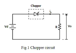
INTRODUCTION: The DC motor is used in many industrial applications requiring variable speed and load characteristics due to its ease of control. A chopper drive-based speed control is widely preferred as far as speed control is concerned. Choppers are mostly applied in electric cars, conversion of wind and solar energy, and DC motor regulators. A chopper uses the high speed to connect and disconnect from a source load. A fixed DC voltage is applied intermittently to the source load by continuously triggering the power switch ON/OFF. The period for which the power switch stays ON or OFF is referred to as the chopper’s ON and OFF state times, respectively.
Chopper
A dc‐to‐dc converter, also known as a dc chopper, is a static device that is used to obtain a variable dc voltage from a constant dc voltage source. Choppers are widely used in trolley cars, battery-operated vehicles, traction motor control, control of large numbers of dc motors, etc. They are also used as dc voltage regulators. Choppers are of two types: (1) Step‐down choppers, and (2) Step‐up choppers. In step‐down choppers, the output voltage will be less than the input voltage, whereas in step‐up choppers output voltage will be more than the input voltage. D.C motor is considered a SISO (Single Input and Single Output) system having torque/speed characteristics compatible with most mechanical loads. This makes a DC motor controllable over a wide range of speeds by proper adjustment of the terminal voltage.
Two quadrant chopper
The chopper can work in two quadrants, it can be motoring and breaking.
2 types of two-quadrant choppers Class - C and Class -D.
i) Class C chopper
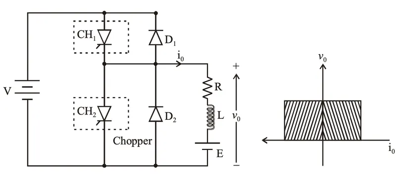
It can operate in both the first as well as the second quadrant. During the first quadrant operation, it acts as a step-down chopper while in the second quadrant it behaves as a step-up chopper. Basically, Class-C is obtained by parallelly connecting Class-A & Class-B chopper. This type of chopper is also known as the Two Quadrant Class-A chopper.
Working:
First quadrant -
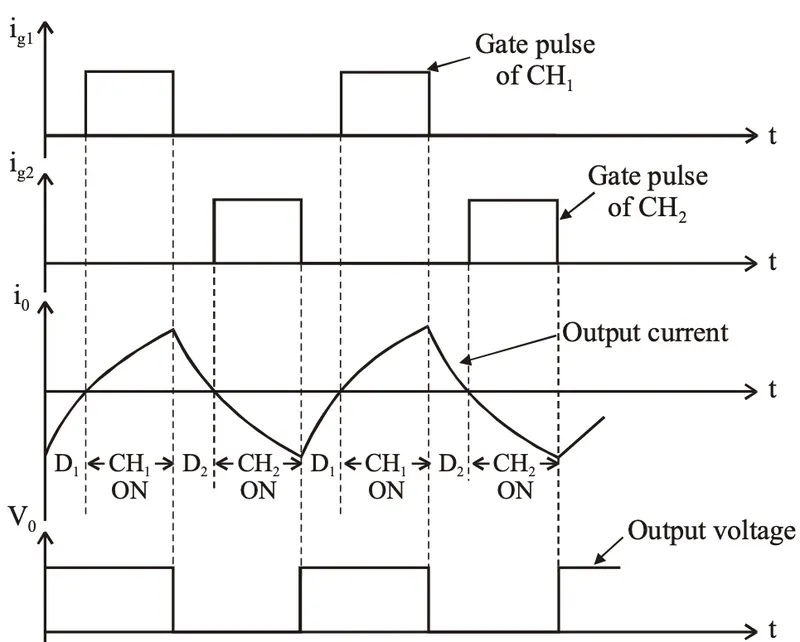
1.When CH1 in ON, the current moves from A->B (+ve), the output voltage is equal to supplied voltage, Vo = V.
2.When CH1 is turned OFF, the charged inductor reverses its polarity and the current flows through D2 in the same direction and the output voltage is equal to zero, Vo= 0.
Second quadrant -
1.CH2 is ON, the voltage E forces current to flow in opposite direction B->A (-ve) through L and CH2, Vo = 0.
2.CH2 is turned OFF the energy stored in the inductor drives current through diode D1 and the supply current flows B->A (-ve), Vo = V.
Theoretical result:
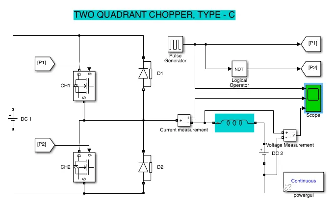
Simulink Model:
Result:
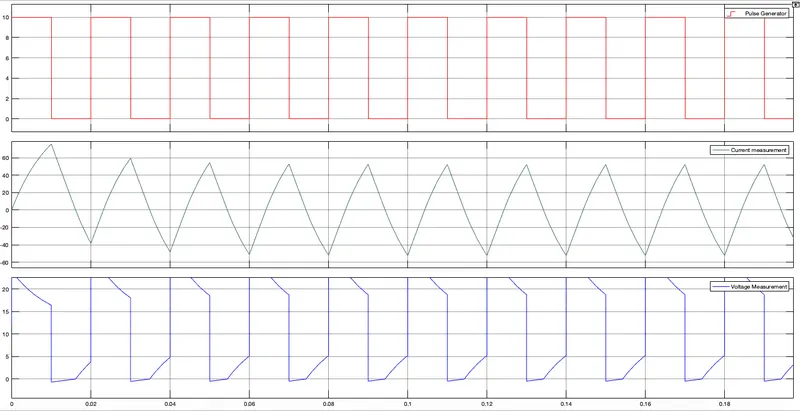
This works both in forward motoring and forward breaking.
Class D chopper
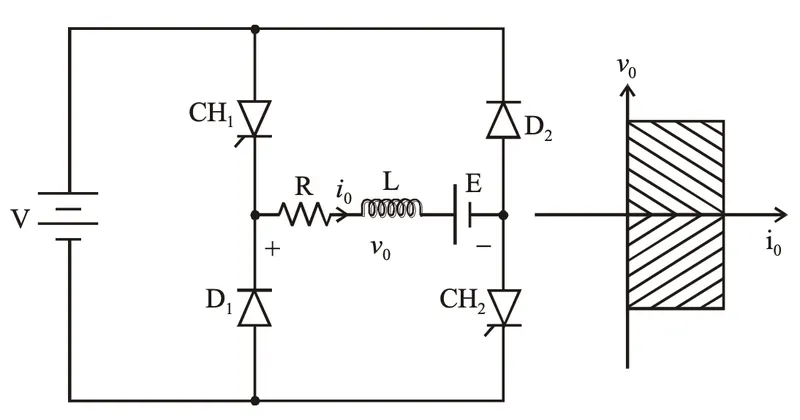
It can operate in the first and fourth quadrant. In this chopper, the direction of load current doesn’t reverse rather the average DC output voltage (Vo) may reverse. Power can either be transferred from source to load or load to source. This chopper is also known as the Two Quadrant Class-B chopper.
Working:
First quadrant-
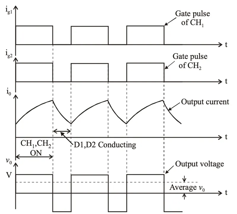
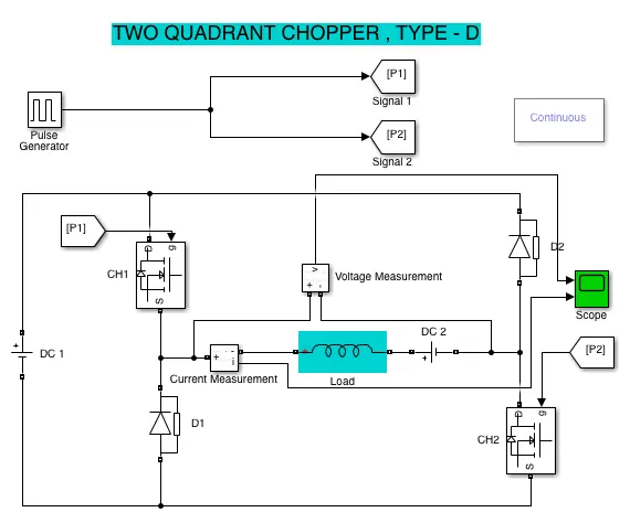
1.CH1 and CH2 both are turned ON, the current moves from A->B (+ve) and the output voltage is Vo = V.
Fourth quadrant-
1.When CH1 and CH2 are turned OFF, the current keeps flowing A->B(+ve) through D2 and D1 due to the energy stored in the inductor L, Vo = -V.
Theoretical result:
Simulink Model:
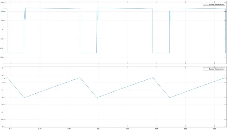
Result:
Note -
1.Output voltage, Vo = +ve if the Ton > Toff
2.Output voltage,Vo = -ve if the Ton < Toff
But current io will always be positive.
This works both in forward motoring and reverses breaking.
PART 3
AIM: Study in detail about BLDC motor.
INTRODUCTION:
Brushless DC Motors or BLDC Motors have become a significant contributor to modern drive technology. Their rapid gain in popularity has seen an increasing range of applications in the fields of Consumer Appliances, the Automotive Industry, Industrial Automation, Chemical and Medical, Aerospace, and Instrumentation.
BLDC Motor
A Brushless DC Motor is similar to a Brushed DC Motor but as the name suggests, a BLDC doesn’t use brushes for commutation but rather they are electronically commutated. In conventional Brushed DC Motors, the brushes are used to transmit the power to the rotor as they turn in a fixed magnetic field.
As mentioned earlier, a BLDC motor used electronic commutation and thus eliminates the mechanically torn brushes.
Construction:
The main design difference between brushed and brushless motors is the replacement of a mechanical commutator with an electric switch circuit. Keeping that in mind, a BLDC motor is a type of synchronous motor in the sense that the magnetic field generated by the stator and the rotor revolve at the same frequency.
Brushless Motors are available in three configurations: single-phase, two-phase, and three-phase. Out of these, the three-phase BLDC is the most common one.
Stator:
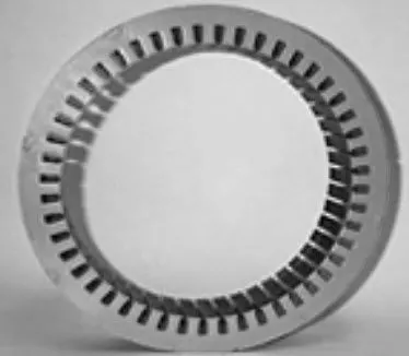
The structure of the stator of a BLDC motor is similar to that of an induction motor. It is made up of stacked steel laminations with axially cut slots for winding. The winding in BLDC is slightly different than that of the traditional induction motor. Generally, most BLDC motors consist of three stator windings that are connected in star or ‘Y’ fashion (without a neutral point). Additionally, based on the coil interconnections, the stator windings are further divided into Trapezoidal and Sinusoidal Motors.
Rotor:
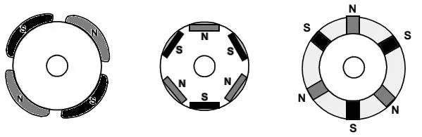
The rotor part of the BLDC Motor is made up of permanent magnets (usually, rare earth alloy magnets like Neodymium (Nd), Samarium Cobalt (SmCo), an alloy of Neodymium, Ferrite, and Boron (NdFeB)).
Based on the application, the number of poles can vary between two and eight with North (N) and South (S) poles placed alternately. The following image shows three different arrangements of the poles. In the first case, the magnets are placed on the outer periphery of the rotor.
Position sensors (Hall sensors):
Since there are no brushes in a BLDC Motor, the commutation is controlled electronically. In order to rotate the motor, the windings of the stator must be energized in a sequence and the position of the rotor (i.e. the North and South poles of the rotor) must be known to precisely energize a particular set of stator windings.
A Position Sensor, which is usually a Hall Sensor (that works on the principle of Hall Effect) is generally used to detect the position of the rotor and transform it into an electrical signal. Most BLDC Motors use three Hall Sensors that are embedded into the stator to sense the rotor’s position.
The output of the Hall Sensor will be either HIGH or LOW depending on whether the North or South pole of the rotor passes near it. By combining the results from the three sensors, the exact sequence of energizing can be determined.
Working Principle:
Consider the following setup of three windings in the stator designated A, B, and C. For the sake of understanding, let us replace the rotor with a single magnet.
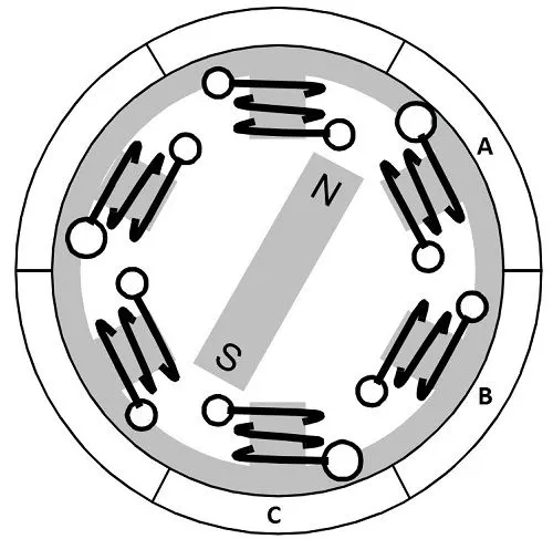
We know that when a current is applied through a coil, a magnetic field is generated and the orientation of the field lines i.e. the poles of the generated magnet will depend on the direction of the current flowing through the coil.
Using this principle, if we supply current to coil A so that it will generate a magnetic field and attract the rotor magnet. The position of the rotor magnet will shift slightly clockwise and will align with A.
If we now pass current through coils B and C one after the other (in that order), the rotor magnet will rotate in the clockwise direction.
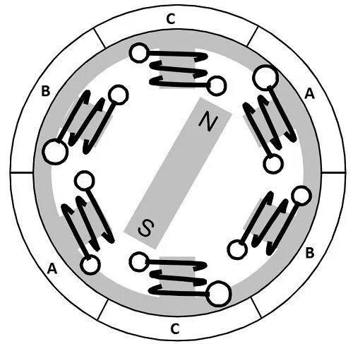
To increase efficiency, we can wind the opposite coils using a single coil so that we get the double attraction. Further increasing the efficiency, we can energize two coils at the same time so that one coil will attract the magnet and the other coil will repel it. During this time, the third will be idle.
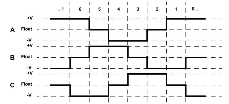
For a complete 3600 rotation of the rotor magnet, six possible combinations of the coils A, B, and C are applicable and are shown in the following timing diagram.
Based on the above diagram, we can confirm that at any time, one phase is positive, one phase is negative and the third phase is idle (or floating). So, based on the inputs from the Hall Sensors, we have two switches in the phases as per the above diagram.
Driving Brushless DC Motors:
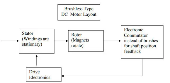
If stator and rotor are essential parts of a BLDC Motor that are integral to it, then the driving electronics are equally essential. A Block diagram of a typical Brushless DC Motor control or drive system is shown in the following image.
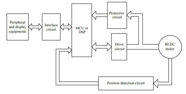
This drive circuitry is often known as Electronic Speed Controller System or simply an ESC. One common setup is called the Full-Bridge Drive Circuit. It consists of an MCU with PWM outputs, six MOSFETS for the three phases of the stator windings, feedback from the Hall sensors, and some power supply-related components.
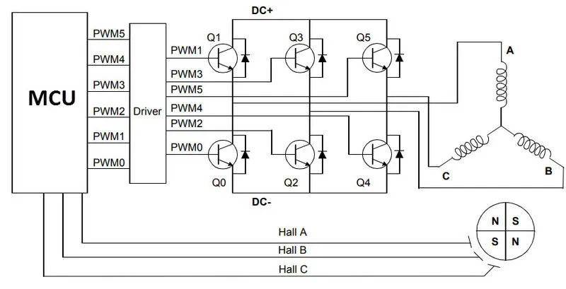
The MCU can be programmed to appropriately switch the MOSFETS based on the data from the Hall Sensors.
Advantages of BLDC Motors
Since BLDC Motors are electronically commutated, there are several advantages over traditional Brushed DC Motors. Some of them are:
- No wear and tear (due to absence of brushes)
- High efficiency
- Better speed vs torque characteristics
- Long life
- Less noise or noiseless operation
- Significantly higher RPM
Applications of Brushless DC Motors
Some of the areas of applications of BLDC Motors are mentioned below:
- Single-speed applications
- Adjustable speed applications
- Position control
- Low noise applications
- High-speed applications