Week-6 Challenge: EV Drivetrain
PART 1
AIM: To Study the types of power converter circuits that are employed in electric and hybrid electric vehicles.
BODY:
Power converter circuits
- These are used everywhere in normal daily routines at home, commercial workplaces or in an industrial environment.
- Due to the high power handling with higher efficiencies, these converters become an integral part of industrial electric drives, high electric power supplies, electric traction systems and automobile control equipments.
- There are different types of power electronic converters used for performing different functions (such as inversion, rectification, etc.) which are rated from a few milliwatts to a few thousand watts.
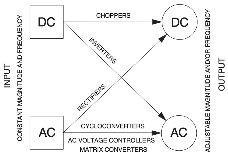
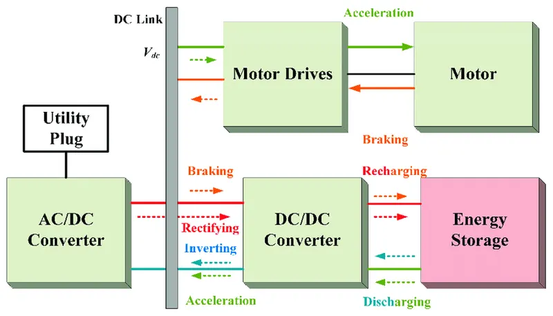
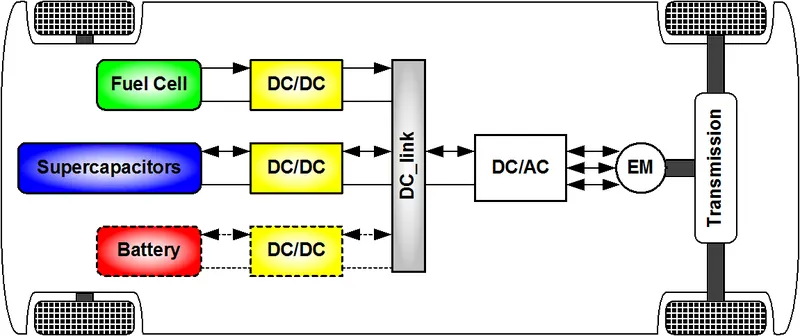
In electric & hybrid electric vehicles (EV/HEV), the power electronic converters are considered as the key elements that interface their power sources to the drive train of the EVs.
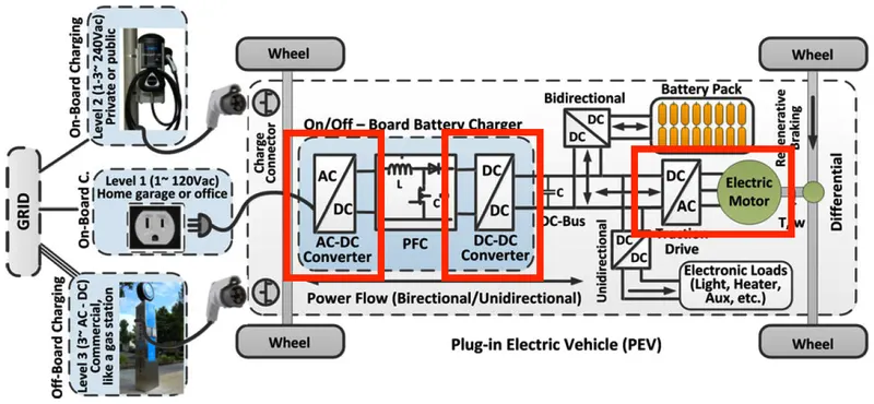
In EVs three types of power electronic circuits are used which are-
- AC to DC
- DC to DC
- DC to AC
1. AC to DC converters or rectifiers
- AC to DC converters are most commonly used in Plug-in Hybrid Electric Vehicles (PHEV) & Plug-in Electric Vehicles (PEV). These vehicles get their propulsion power from an external electricity source (charging stations) which is alternating current. The battery needs to be charged using a direct current source. For this purpose, AC to DC converter is employed in a PHEV & PEV.
- An AC to DC converter is also called a rectifier, which converts AC supply from main lines to DC supply for the load.
- The block diagram of an AC to DC converter is shown in figure below.
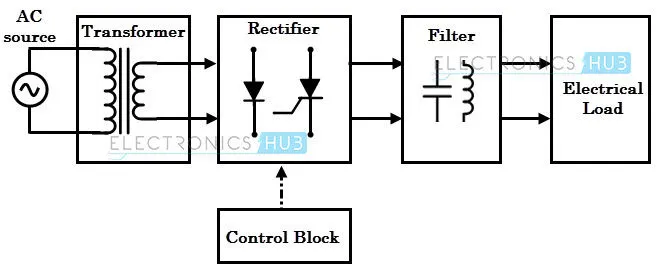
- The essential components in this rectifier include transformer, switching unit, filter and a control block.
- Here, the transformer adjusts the primary AC source supply to the input of rectifier stage. Usually it is a step-down transformer that reduces the supply voltage to a circuit operating range.
- These are used in onboard chargers in electric vehicles.
2. DC to DC or choppers
- DC traction systems, control of large DC motors, battery operated vehicles require variable DC to produce variable speed, so a power conversion device is needed.
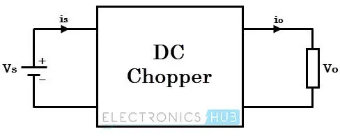
- A DC chopper is a static device that converts a fixed input DC voltage to variable DC output or a fixed DC output of different magnitude (which can be lower or higher) than input value. The block diagram of a DC chopper is shown in figure below.
-
The chopper circuit is connected between DC input source and DC load. This chopper consists of power electronic switching devices such as thyristors which are connected in such a way that they produce required DC voltage to the load.
-
The output voltage is controlled by adjusting ON time of the thyristor (or switch) which turn changes the width of DC voltage pulse at the output. This method of switching is called as pulse width modulation (PWM) control.
-
The output of the chopper can be less or greater than the input and also it can be fixed or variable. These can be unidirectional or bidirectional devices based on the application it is intended for.
3. DC to AC or inverters
- The DC/AC converter is required to convert the dc power to a suitable ac power for the electrical machine. The power output from battery pack (DC current) is converted using inverter to be used in electric motor (AC current).
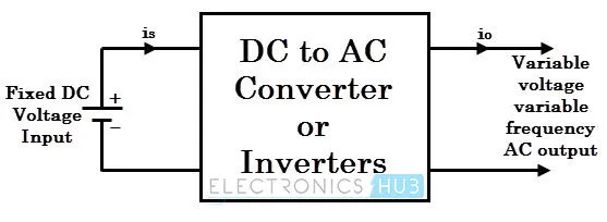
- These converters are connected between DC source of fixed input, and variable AC load. Most commonly, these DC to AC converters are called as inverters. An inverter is a static device that converts fixed DC supply voltage to variable AC voltage.
- Here the fixed DC voltage is obtained from batteries or by DC link in most power electronic converter. The output of the inverter can be variable/ fixed AC voltage with variable/fixed frequency.
- This conversion from DC to AC along with variable supply is produced by varying the triggering angle to the thyristors. Most of the thyristors used in inverters are employed with forced commutation technique.
PART 2
AIM: To find the steady state speed of the EV with duty cycle of 70% and given parameters.
BODY:
Given
Motor and Controller Parameters:
Rated Armature voltage= 72 V
Rated armature current= 400 A
Ra= 0.5Ω, KΦ= 0.7 Volt second
Chopper Switching frequency= 400 Hz
The vehicle speed-torque characteristics are given by the below equation

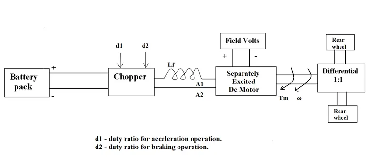
Power train of the EV
CALCULATIONS:
Duty cycle of d = 70% means
On time = 7 seconds
Off time = 3 seconds
So,
Vavg = Vbat * d
Vavg = 72*(0.70)
Vavg = 50.4 V
As we Know DC motor characteristics
W = Vavg /K - Ra*Tm/(K)2 or Tm = Vavg *K/Ra - (K)2*W/Ra
Putting Vavg = 50.4, K = 0.7, Ra = 0.5
Tm = 70.56 - (0.98)*W;
Tv =24.7 + (0.0051)*W2 (Given)
To Get the steady state speed
Tv = Tm
24.7 + (0.0051)*W2 = 70.56 - (0.98)*W
W2 + (192.157)*W - 8992.157 = 0
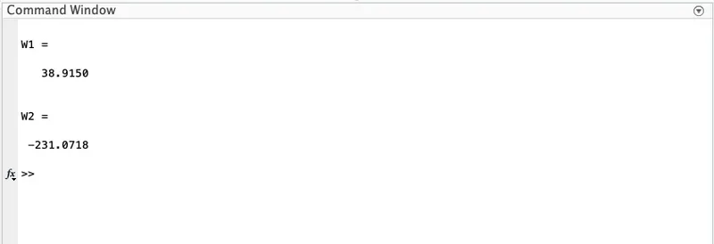
W = 38.915 rad/s or -231.071 rad/s
As W can’t be negative
Steady state speed is W = 38.915 rad/s.
MATLAB CODE:
%To find steady state speed
clear all
close all
clc

%speed
W = linspace(0,100,50);

%Speed-torque characteristics
T_v = 24.7 + (0.0051)*(W).^2; %vehicle
T_m = 70.56 - (0.98)*(W); %motor

%steady state speed
%T_v = T_m
%W^2 + 192.157 - 8992.157 = 0

A = 1;
B = 192.1568;
C = -8992.1568;
W1 = ((-B)+((B^2-4*A*C))^0.5)/(2*A)
W2 = ((-B)-((B^2-4*A*C))^0.5)/(2*A)

%plotting
hold on
grid on
plot(W,T_v,'r','linewidth',2)
plot(W,T_m,'b','linewidth',2)
xlabel('Speed (rad/s)')
ylabel('Torque (Nm)')
legend('vehicle','Motor')
axis([0 100 0 100])
%end
RESULT:
Torque vs Speed graph
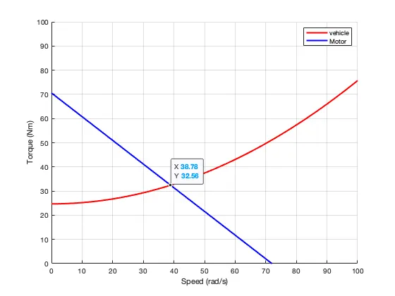
According to the graph
W = 38.78 rad/s
So percentage is
Error = (39.91 - 38.78)*100/38.78 = 0.33 %
PART 3
AIM: Explain in breif about Induction Versus DC Brushless Motors by Wally Rippel, Principal Power Electronics Engineer, Tesla
BODY:
- The author starts by describing the types of Engines and use this as an analogy to show that just like motors there are so many types of engines, each has its own characteristics and own use with respect to the requirements such as price and/or performance.
- He then takes a closer look into both the types of motor i.e. DC Brushless and induction motor, explaining the workings of both.
- He then puts forward advantages and disadvantages of both the motors.
- Brushless DC motor have some advantages like: much less rotor heat is generated with the DC brushless drive. The peak point energy efficiency for a DC brushless drive will typically be a few percentage points higher than for an induction drive. Some disadvantages of Brushless DC motor are: as machine size grows, the magnetic losses increase proportionately and part load efficiency drops. Permanent magnets are expensive and difficult to handle due to very large forces that come into play when anything ferromagnetic gets close to them.
- Induction motor have some advantages like: it has no magnets. The motor has the ability to start under load. No inverter is needed. Some disadvantages of Induction motors are: They cannot operate from DC; AC is a must. Shaft speed is proportionate to line frequency. Hence, when used with utility power, they are constant speed machines. When operated from utility power, they have limited starting torque and somewhat limited running peak torque capabilities, when compared to DC type machines.
CONCLUSION:
In the end he concludes that that DC brushless drives will likely continue to dominate in the hybrid and coming plug-in hybrid markets, and that induction drives will likely maintain dominance for the high-performance pure electrics.
END
SOURCES:
https://charge.net.nz/faq/what-is-the-difference-between-ac-and-dc-charging/
https://www.tesla.com/blog/induction-versus-dc-brushless-motors