Project-1: Powertrain for aircraft in runways
PART-A
PART - 1
AIM: To find Various weights associated with aircraft.
BODY:
A. Design weights limits (structural design weights)
An aircraft's gross weight is limited by several weight restrictions in order to avoid overloading its structure or to avoid unacceptable performance or handling qualities while in operation.
Aircraft gross weight limits are established during an aircraft's design and certification period and are laid down in the aircraft's type certificate and manufacturer specification documents.
|
Type |
Description |
|
Maximum design taxi weight (MDTW) |
The maximum design taxi weight (also known as the maximum design ramp weight (MDRW)) is the maximum weight certificated for aircraft maneuvering on the ground (taxiing or towing) as limited by aircraft strength and airworthiness requirements. |
|
Maximum design take-off weight (MDTOW) |
Is the maximum certificated design weight when the brakes are released for take-off and is the greatest weight for which compliance with the relevant structural and engineering requirements has been demonstrated by the manufacturer. |
|
Maximum design landing weight (MDLW) |
The maximum certificated design weight at which the aircraft meets the appropriate landing certification requirements. It generally depends on the landing gear strength or the landing impact loads on certain parts of the wing structure. |
|
Maximum design zero-fuel weight (MDZFW) |
The maximum certificated design weight of the aircraft less all usable fuel and other specified usable agents (engine injection fluid, and other consumable propulsion agents). It is the maximum weight permitted before usable fuel and other specified usable fluids are loaded in specified sections of the airplane. |
|
Minimum flight weight (MFW) |
Minimum certificated weight for flight as limited by aircraft strength and airworthiness requirements. |
B. Authorised weight limits
Aircraft authorized gross weight limits (also referred to as certified weight limits) are laid down in the aircraft flight manuals (AFM) and/or associated certificates of airworthiness (C of A). The authorized or permitted limits may be equal to or lower than the structural design weight limits.
The authorized weight limits that can legally be used by an operator or airline are those listed in the AFM and the weight and balance manual.
|
Type |
Description |
|
Maximum taxi weight (MTW) |
The maximum taxi weight (MTW) (also known as the maximum ramp weight (MRW) is the maximum weight authorized for maneuvering (taxiing or towing) an aircraft on the ground as limited by aircraft strength and airworthiness requirements. It includes the weight of the taxi and run-up fuel for the engines and the APU. It is greater than the maximum take-off weight due to the fuel that will be burned during the taxi and runup operations. |
|
Maximum take-off weight (MTOW) |
The maximum take-off weight (also known as the maximum brake-release weight) is the maximum weight authorized at brake release for take-off, or at the start of the take-off roll. The maximum take-off weight is always less than the maximum taxi/ramp weight to allow for fuel burned during taxi by the engines and the APU. |
|
Maximum landing weight (MLW) |
The maximum weight authorized for the normal landing of an aircraft. The MLW must not exceed the MTOW. The operation landing weight may be limited to a weight lower than the Maximum Landing Weight |
|
Maximum zero-fuel weight (MZFW) |
The maximum permissible weight of the aircraft less all usable fuel and other specified usable agents (engine injection fluid, and other consumable propulsion agents). It is the maximum weight permitted before usable fuel and other specified usable fluids are loaded in specified sections of the airplane. |
Some of the famous airplane along with their MTOW are.
|
Type |
MTOW (kg) |
|
Antonov An-225 |
640,000 |
|
Scaled Composites Model 351 Stratolaunch |
589,670 |
|
Airbus A380-800 |
575,000 |
|
Boeing 747-8F |
447,700 |
|
Boeing 747-8 |
443,613 |
|
Boeing 747-400ER |
421,770 |
|
Douglas DC-8-32 |
140,000 |
|
Tupolev Tu-154M |
104,000 |
|
Bombardier Q400 |
28,000 |
|
ATR 42-500 |
18,600 |
|
Bae Jetstream 41 |
10,890 |
|
Learjet 75 |
9,752 |
|
Cessna citation Cj4 |
7,761 |
PART-2
AIM: To find the difference between Ground speed and Airspeed during aircraft application.
BODY:
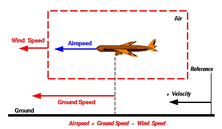
Ground speed
It is the horizontal speed of an aircraft relative to the ground. An aircraft heading vertically would have a ground speed of zero. The information displayed to passengers through the entertainment system of airline aircraft often gives the aircraft ground speed rather than airspeed. For a reference point picked on the ground, the aircraft moves relative to the reference point at the ground speed. Ground speed is also a vector quantity so a comparison of the ground speed to the wind speed must be done according to rules for vector comparisons.
Wind speed
For a reference point picked on the ground, the air moves relative to the reference point at the wind speed. Notice that the wind speed is a vector quantity and has both a magnitude and a direction. The direction is important. A 20-mph wind from the west is different from a 20-mph wind from the east. The wind has components in all three primary directions (north-south, east-west, and up-down). In this figure, we are considering only velocities along the aircraft's flight path. Positive velocity is defined to be in the direction of the aircraft's motion. We are neglecting crosswinds, which occur perpendicular to the flight path but parallel to the ground, and updrafts and downdrafts, which occur perpendicular to the ground.
Airspeed
The important quantity in the generation of lift is the relative velocity between the object and the air, which is called the airspeed. Airspeed cannot be directly measured from a ground position but must be computed from the ground speed and the wind speed. Airspeed is the vector difference between ground speed and wind speed.
Airspeed = Ground Speed - Wind Speed
On a perfectly still day, the airspeed is equal to the ground speed. But if the wind is blowing in the same direction that the aircraft is moving, the airspeed will be less than the ground speed.
Difference between ground speed and airspeed
As mentioned above, true airspeed is simply the speed at which an aircraft is moving relative to the air it is flying in. As such, it’s also the speed at which the air is flowing around the aircraft’s wings.
Ground speed, on the other hand, is the aircraft’s speed relative to the ground. One thing that should be noted here is that it. it's horizontal rather than vertical speed – an aircraft climbing completely vertically would have a ground speed of zero.
In other words, while airspeed is what determines whether there is enough airflow around an aircraft to make it fly, ground speed is what determines how fast an aircraft will get to its destination.
PART-3
AIM: To find the reason why is it not recommended to use aircraft engine power to move it on the ground at the Airport.
BODY:
Aircraft can move using their own engine power all the time on the airport apron and taxiways under their own power to go towards runways and after landing taxi to their assigned gate. But the thrust produced resulting in jet blast might cause damage to the terminal building or equipment. Engines close to the ground may also blow sand and debris forward and then suck them into the engine, causing damage to the engine. A pushback is therefore the preferred method to move the aircraft away from the gate. And also, it can reduce the cost of fuel. Taxiing can save money.
- Effectively a loss of control can happen, especially during high power engine running. Damage can occur to the aircraft itself, other aircraft nearby, or to airside structures.
- There is a risk of injury to ground support personnel who may be in relatively close proximity to the aircraft.
- It is easier for the truck drivers to see the surroundings better than the pilot sitting in the cockpit with a limited window. The pushback driver knows the airport better than the pilot.
- It also saves fuel.
The plane engines are very loud. When more than one plane will add up their sound then it will not be pleasant for passengers and others near the airport.
PART-4
AIM: To find how an aircraft is pushed to the runway when it's ready to take off.
BODY:
Taxiing
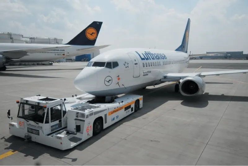
Taxiing is the movement of an aircraft on the ground, under its own power, in contrast to towing or push-back where the aircraft is moved by a tug. The aircraft usually moves on wheels, but the term also includes aircraft with skis or floats. An airplane uses taxiways to taxi from one place on an airport to another; for example, when moving from a hangar to the runway.
Towing
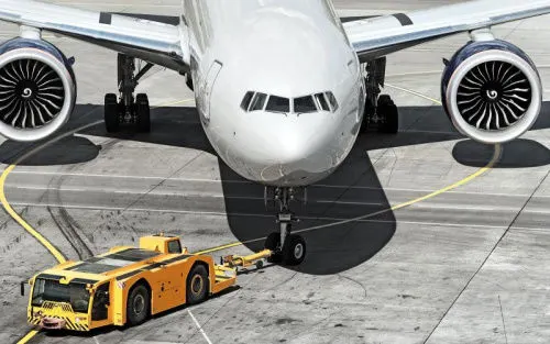
The movement of large aircraft about the airport, flight line, and hangar is usually accomplished by towing with a tow tractor. In the case of small aircraft, some moving is accomplished by hand pushing on the correct areas of the aircraft. Aircraft may also be taxied about the flight line but usually only by certain qualified personnel. Towing aircraft can be a hazardous operation, causing damage to the aircraft and injury to personnel, if done recklessly or carelessly. This article outlines the general procedure for towing aircraft. However, specific instructions for each model of aircraft are detailed in the manufacturer's maintenance instructions and are to be followed in all instances.
PART -5
AIM: To Learn about take-off power, tire design, rolling resistance, tire pressure, brake forces when landing.
BODY:
a. Take-off power
Take-off power is the phase of flight in which an aerospace vehicle leaves the ground and becomes airborne. For the aircraft that take off horizontally, this usually involves starting with a transition from moving along the ground on a runway. The take-off speed required varies with air density, aircraft gross weight, & aircraft configuration.
The power from the engine of the aircraft used to achieve the flight is called take-off power & for light aircraft usually, full power is required during take-off, large transport category (airliner) may use reduced power for take-off, where less than full power is applied in order to prolong engine life, reduce maintaining cost, and reduce noise emissions.
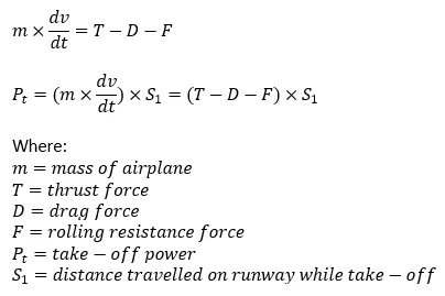
During the take-off run, the imbalance in these forces will produce an acceleration along the runway. Take-off power can be predicted using a simple measure of the acceleration of the aircraft along the runway based on force equilibrium.
b. Tire design
Aircraft tires are designed to withstand extremely heavy loads by absorbing shocks and thereby providing a cushioning effect. The number of tires required for an aircraft depends on the total weight of the aircraft as the weight needs to be distributed evenly. These facilitate stability in high crosswind conditions, channelize the water away for preventing skidding, and helps to give a good braking effect.
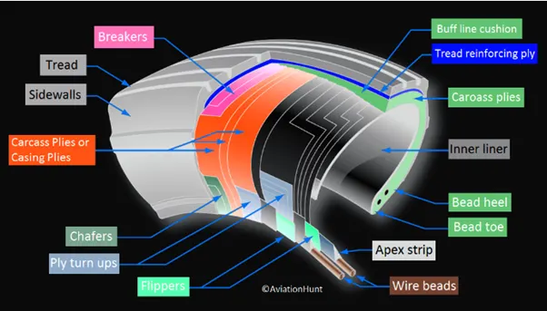
Tires are usually inflated by nitrogen air in order to reduce expansion and contraction from extreme changes in ambient pressure and temperature. This type of inert gas will eliminate the possibility of a tire explosion.
c . Rolling resistance
Rolling resistance or rolling drag is the force resisting the motion when the body rolls on a surface and it is mainly caused by non-elasticity that is, not all the energy needed for deformation of wheel is recovered when the pressure is removed.
Usually, aircraft have a very low rolling resistance coefficient of 0.06.
Rolling resistance can be expressed as
d. Tyre pressure
Aircraft tires are designed to withstand heavy loads and shocks during landing and take-off operations and also need to distribute weight evenly. Aircraft tires are generally operated at high pressures up to 200 Psi (16 Bar, 1400 kPa) for airliners and even higher for business jets. As per research and testing, it is found that aircraft tires are able to sustain pressure up to 800 psi. During testing the tires have to be filled with water in order to prevent the test room from being blown apart by the energy that would release by the gas when the tire bursts.
Aircraft tires are usually inflated with nitrogen to minimize expansion & contraction from the extreme changes in ambient temperature & pressure experienced during flight. Dry nitrogen expands at the same rate as dry atmospheric gases (Normal air has about 80% Nitrogen), but common compressed air sources may contain moisture which increases the expansion rate with temperature. The requirement that an inert gas, such as nitrogen be used instead of air for inflation of tires for certain transport category airplanes is prompted by at least 3 cases in which the oxygen-filled tires combined with volatile gases given off by severely overheated tire and exploded upon reaching auto-ignition temperature the use of inert gas for tire inflation will eliminate the possibility of a tire explosion.
There are 2 primary parameters that are hazardous to the aircraft tires:
I)Deflation:
Here the tire deflates in a controlled manner with a minimum direct consequence to other systems.
II)Explosive breakup:
In this case, the tire deflates or bursts in an uncontrolled manner with a probability of causing damage to other secondary systems, which further can cause a major crash-landing incident.
e. Brake forces:
Braking an aircraft is a challenging job for most pilots especially during landing in a rainy and crosswind environment. In order to deal with these kinds of problems pilots usually make use of spoilers and reverse thrust methods in order to have a safe landing so that the energy required to apply brakes on tires can be reduced and henceforth they do not skid.
Aircraft brakes stop moving aircraft by converting its Kinetic Energy to heat energy by means of friction between rotating & stationary discs located in brake assemblies in the wheels. Brakes provide this critical stopping function during landings to enable airplanes to stop within the length of the runway.
Following braking devices are used to decelerate the aircraft –
- Ground Spoilers.
- Wheel Brakes (Including Anti-Skid systems & Auto-Brake systems).
- Thrust Reverser.
Ground Spoilers –
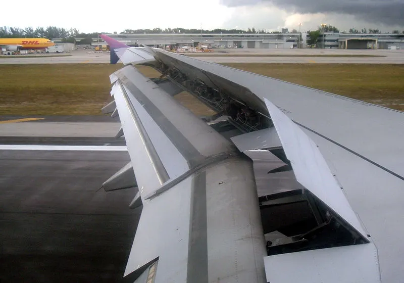
Ground spoilers usually deploy automatically (if armed) upon main-landing-gear-touchdown or upon activation of thrust reversers.
Ground spoilers provide 2 aerodynamic effects –
- Increased aerodynamic drag contributes to aircraft deceleration.
- Lift-Dumping increases the load on the wheels and thus increases the wheel braking efficiency.
Wheel Brakes -
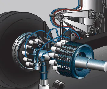
Braking action results from friction force between the tires & the runway surface.
The friction force is affected by –
- Wheel speed (i.e., Free rolling, skidding, or rocked)
- Tyre condition & pressure (i.e., friction surface)
- Runway Condition (i.e., Runway friction coefficient)
The load applied on the wheel.
Braking force is equal to the load applied on the wheel multiplied by the runway friction coefficient.
Anti-skid systems are designed to maintain the wheel-skidding factor (also called the slip ratio) near the point providing the maximum friction force, which is approximately 10% on a scale from 0% to 100% locked wheel). Autobrake systems are designed to provide a selectable declaration rate, typically between three knots/sec. to six knots/sec. When a low auto brake deceleration rate is selected & the brake pressure is applied usually after a specific time delay to give priority to the thrust reverser deceleration force at high airspeed.
Thrust Reversers –
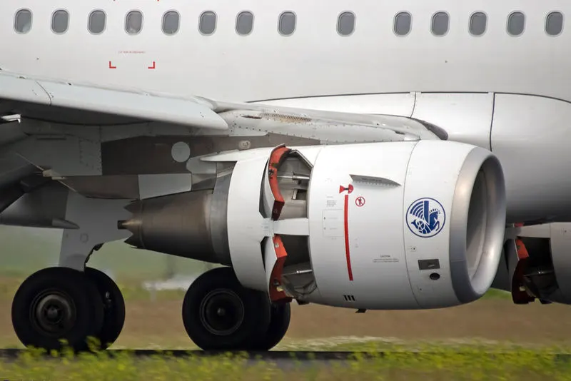
Thrust reversers provide a deceleration force that is independent of runway conditions. Thrust reverser efficiency is higher at high airspeed therefore, thrust reversers must be selected as early as possible after touchdown (in accordance with standard operating procedures). Thrust reversers should be returned after reverse idle at low airspeed (to prevent engine stall or foreign object damage) & stowed a taxi speed. Nevertheless, maximum engine speed can be maintained to a complete stop in an emergency.
PART-B
PART-6
AIM: To develop a model for the calculation of force and power required to push/pull an aircraft by a towing vehicle using Simulink.
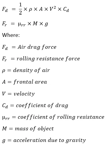
EQUATIONS USED:
BODY:
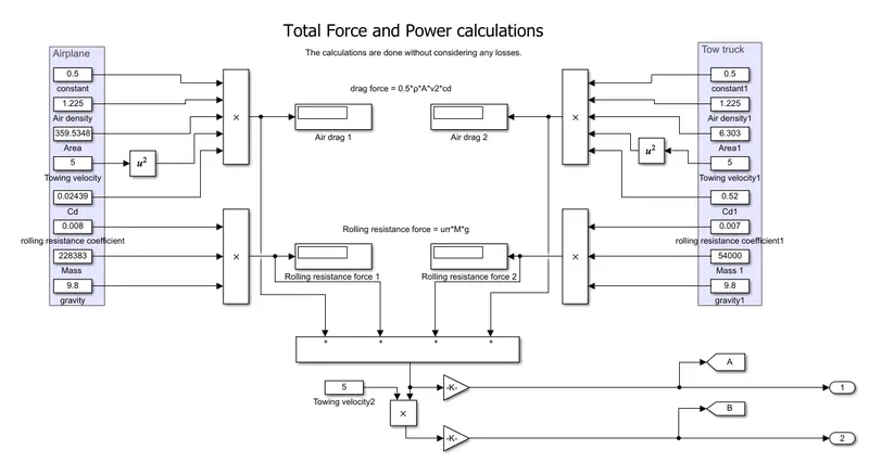
When the tow truck is towing the airplane to the runway. The airplane experiences Air drag force (Fd) as well as the rolling resistance force (Frr) at the wheels, the same is for tow truck engaged in pushback or pull conditions. So, the total force experienced by the tow truck will be equal to the sum of all the forces.

And the total power required for the operation will be

Where V is the velocity during towing operation.
Taking necessary assumptions, the force and power is calculated using simple excel calculator.
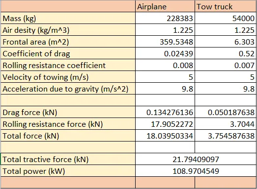
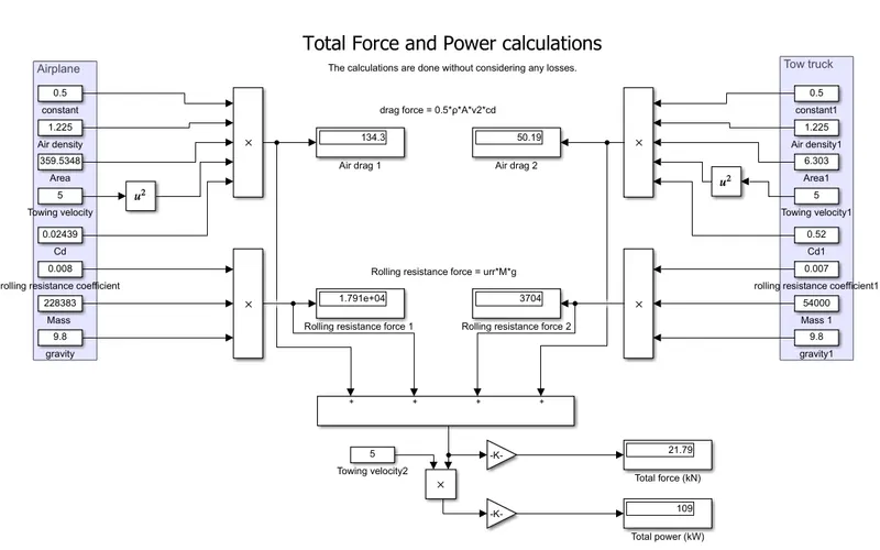
The same can be done using Simulink.
SIMULINK MODEL:
RESULT:
The total force and power required for the towing operation is 21.79 kN and 109 kW respectively.
PART-7
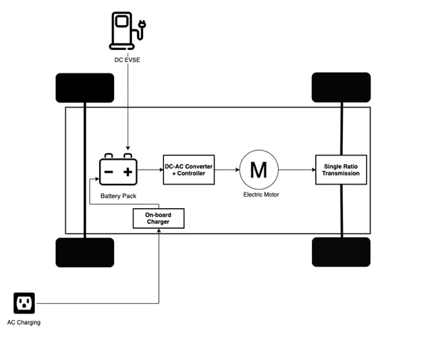
AIM: To design an electric powertrain of a tow truck used for the application of towing an airplane using Simulink.
OBJECTIVE:
1.To determine the type and parameters of the motor to be used.
2.To determine power rating.
3.To determine energy requirement.
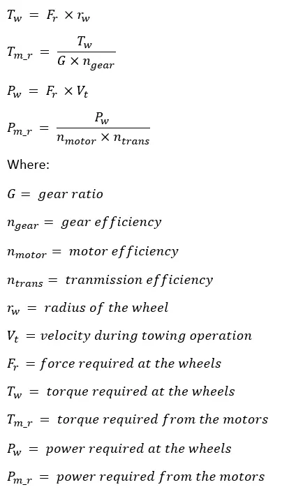
EQUATIONS USED:
BODY:
The total force and power required for the towing operation is 21.79 kN and 109 kW respectively as calculated previously.
Using necessary assumptions, the following parameters are calculated.
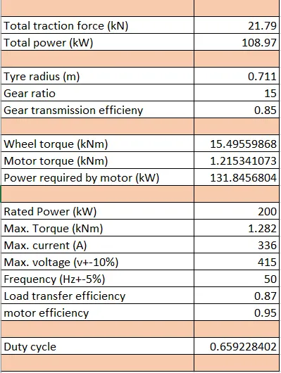
Using Simulink for the same.
SIMULINK:
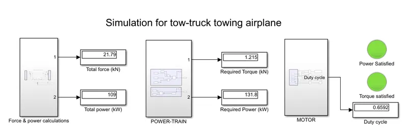
OVERALL MODEL:
FORCE AND POWER CALCULATIONS:
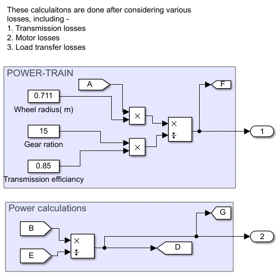
POWER-TRAIN:
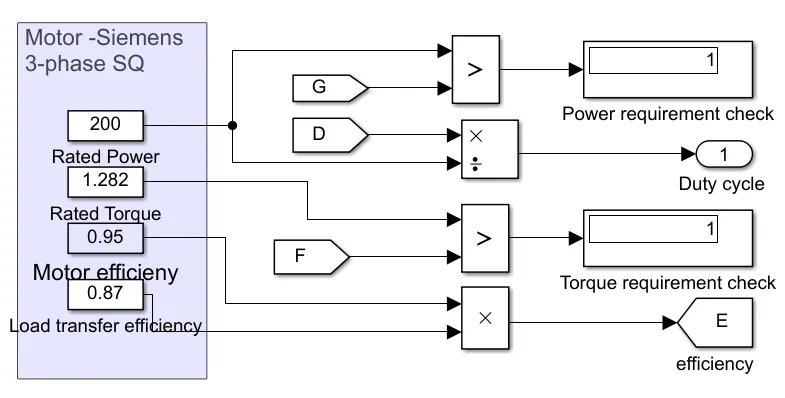
MOTOR:
MOTOR SELECTION:
POWER TRAIN DESIGN:
RESULT:
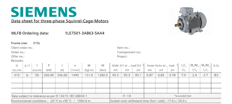
1. As we can see the torque and power required from the motor is 1.21 kN and 131.84 kW respectively which can be fulfilled by the motor we choose having 200 kW as rated power and 1.28kN as rated torque.
2. To provide the required power the motor should be run between 0 to 65.92% duty cycle.