Implementing control logic of a "washing machine" & "Gear shifter"using Stateflow
This project is based on control logic and state flow.
Part-1
AIM: Implement control logic of a “washing machine” using Stateflow.
BODY:
Conditions:
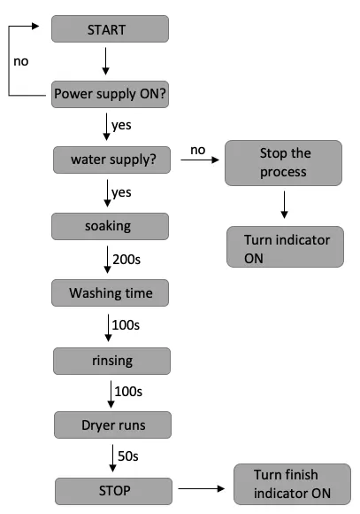
- If the power supply is available, the system gets activated.
- If the Water supply is not available, the process stops and is indicated through LED.
- Soaking time should be 200s followed by Washing time of 100s.
- Then rinsing happens for next 20s & dryer runs for 50s.
- After all the processes have completed the stop LED turns ON.
Flow chart:
Simulink chart model:
Explanation:
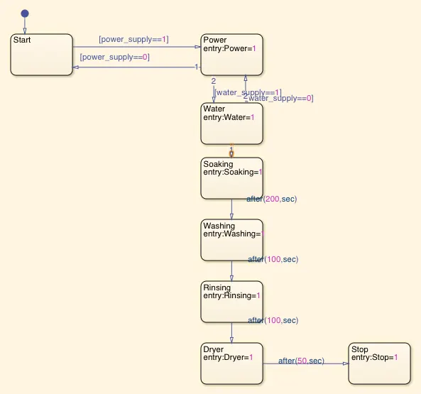
- The inputs to the chart are power_supply and water_supply in the form of ‘0’ or ‘1’.
- ‘0’ representing OFF state and ‘1’ representing ON state.
- When power_supply = 0, the machine will not start and power led will remain red.
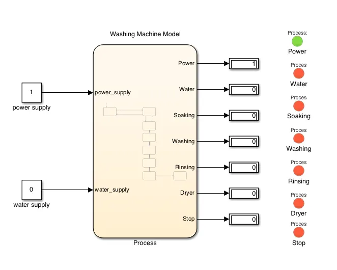
- When power_supply = 1, the process goes to 'Power' block and the value of 'Power' equals 1, then process goes to 'Water' block but since water_supply = 0, the machine will start and turn off because water is not available and water led will remain red.
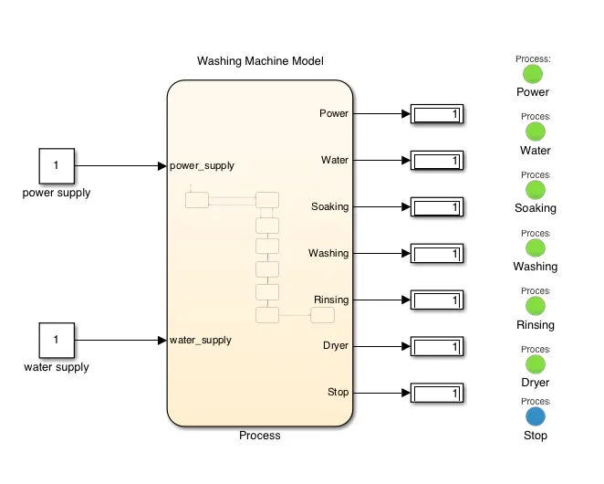
- When power_supply = 1, the process goes to 'Power' block and the value of 'Power' equals 1, then process goes to 'Water' block and since water_supply = 1, the process goes to 'Soaking' block and so on after the designated delays and the machine will turn off after all the processess and stop indicator will turn blue.
Result:
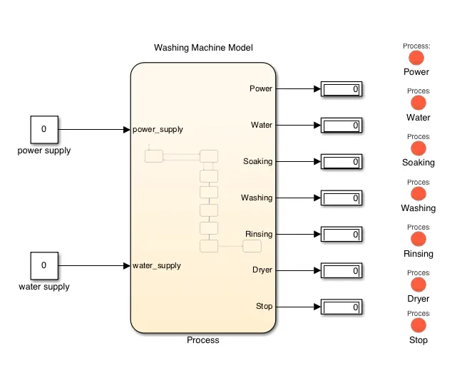
Case 1: When Power supply is OFF.
explanation: The machine did not start and power led remained red.
Case 2: When Power supply is ON & Water supply is OFF.
explanation:The machine starts and turn off because water is not available and water led remained red.
Case 3: When Power supply is ON & Water supply is ON.
explanation: The machine runs and turn off after all the washing process are finished and stop indicator turns blue.
PART-2
AIM: Implement control logic of a “Gear shifter” using Stateflow.
BODY:
Conditions:
The gear should change according to the below given table.
|
Speed Range (kmph) |
Gear |
|
0-15 |
1 |
|
16-25 |
2 |
|
26-40 |
3 |
|
41-60 |
4 |
|
>60 |
5 |
Simulink model:
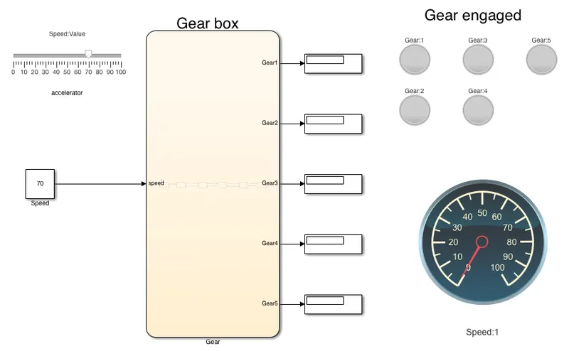
Chart:

Explanation:
1. The input of the model is speed which can take any value between 0-100 and can be changed at any instant with the help of slider.
2. Each Gear can take a value of either '0' or '1'. '0' being not engaged and '1' being engaged and this value is connected to lamp block for each individual gear which indicates which gear is engaged at present.
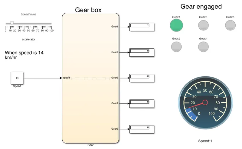
3. When the speed value is less than or equal to 15 kmph the value of 'Gear1' becomes 1 and turns ON the indicator LED.
4. When the speed value is greater than 15 the value of 'Gear1' becomes 0 on exit and the value of 'Gear2' becomes 1 and the indicator LED tirns ON.
5. The process is same for different speeds and their corresponding LED turns ON when that particular Gear is engaged.
Results:
case-1:When the speed is 14 kmph, Gear 1 is engaged.
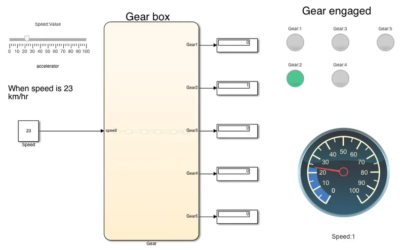
case-2:When the speed is 23 kmph, Gear 2 is engaged.
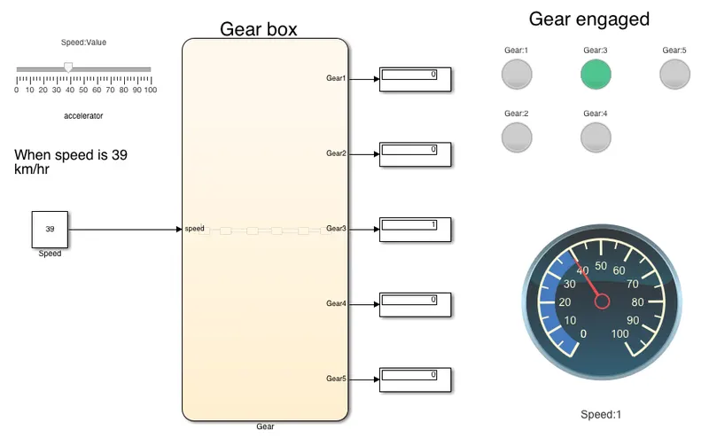
case-3:When the speed is 39 kmph, Gear 3 is engaged.
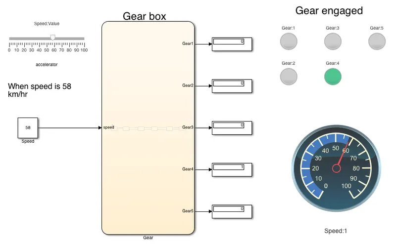
case-4:When the speed is 58 kmph, Gear 4 is engaged.
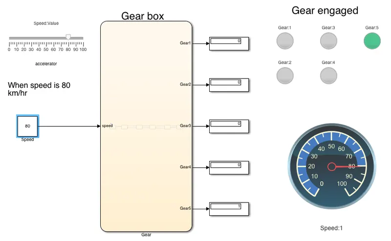
case-5:When the speed is 80 kmph, Gear 5 is engaged.