Week 12 - Validation studies of Symmetry BC vs Wedge BC in OpenFOAM vs Analytical H.P equation
Symmetry Boundry Condition:
The symmetry boundary condition defines a mirror face/surface. It should only be used if the physical object or geometry and the expected flow field pattern of the developed solution are mirrored along that surface. By using this boundary condition, the domain can essentially be halved, reducing the time to achieve a solution.
This boundary condition is used to apply mirror-symmetry conditions to a structure.
It can be applied to faces of a structure and no other user input is needed. If a symmetry plane condition is applied to a face, the displacement of this face is locked in a normal direction but free to slide in tangential directions.
Wedge Boundry Condition:
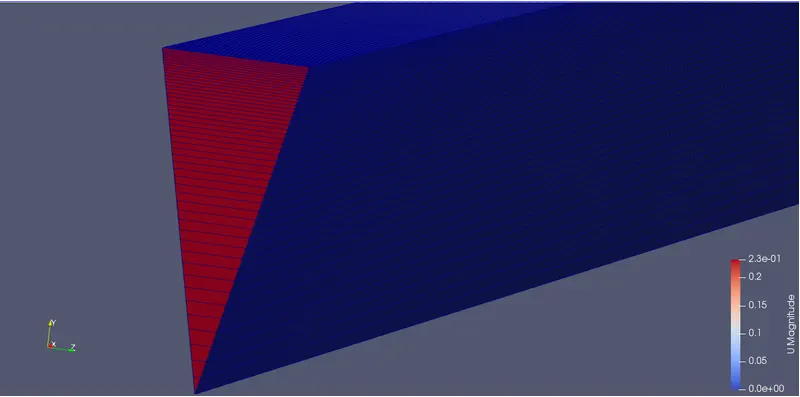
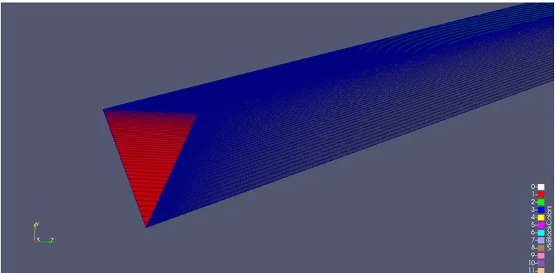
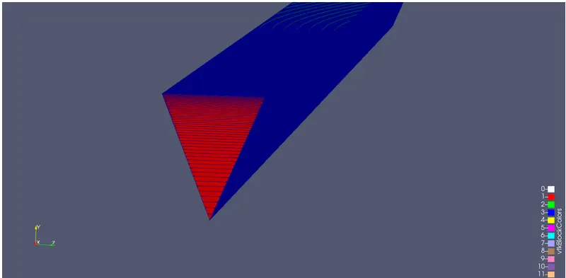
Applied in pairs to 2-D rotationally symmetric cases to represent planes in the swirl direction.
- The patch pair must straddle a co-ordinate plane equally
- Separation between
wedgepatch pairs must be- a single layer of cells
- points should appear collocated when viewed in the mid-plane normal direction
- Particles will be snapped to the mid-plane between pairs of
wedgepatches
Hagen-Poiseulle Equation:
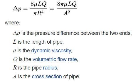
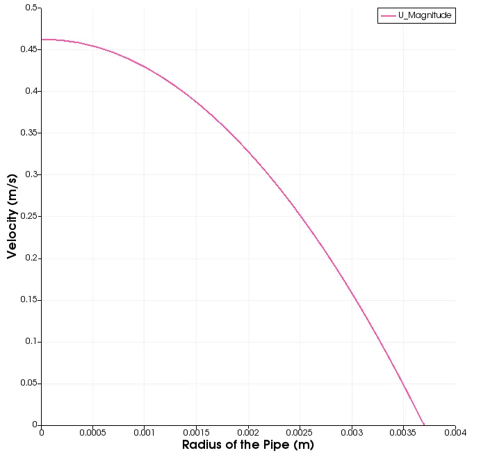
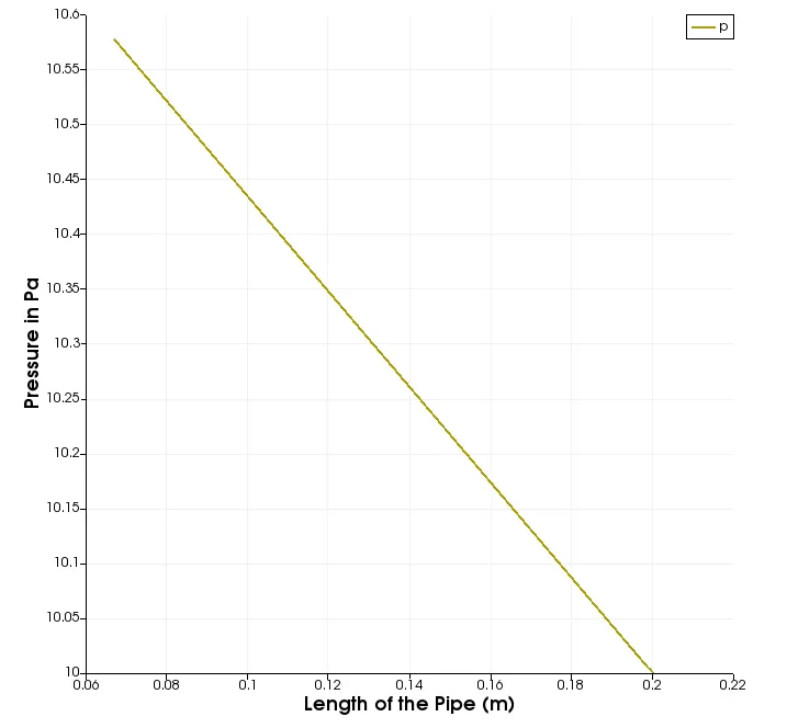
In nonideal fluid dynamics, the Hagen–Poiseuille equation, also known as the Hagen–Poiseuille law, Poiseuille law, or Poiseuille equation, is a physical law that gives the pressure drop in an incompressible and Newtonian fluid in laminar flow flowing through a long cylindrical pipe of constant cross-section.
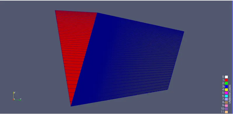
Simulation for 10 angles:
Follows the same flow of steps as in previous challenges:
Tutorial ---> incompressible----->icofoam
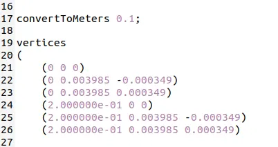
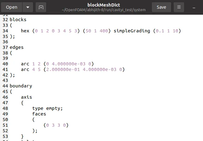
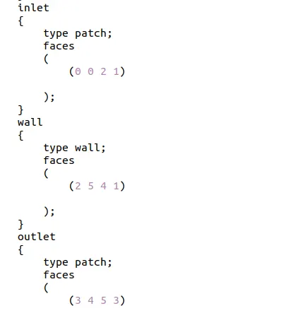
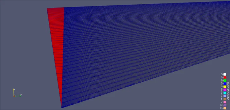
Block Dict File:
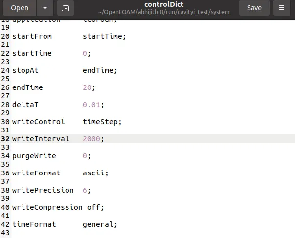
ControlDict File:
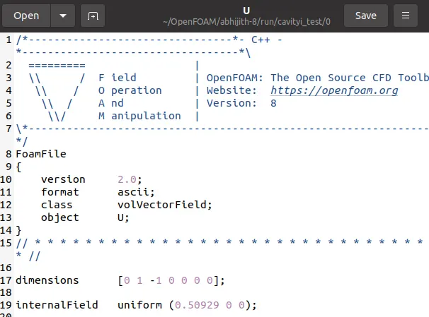
Vector Filed 'U':
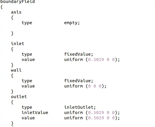
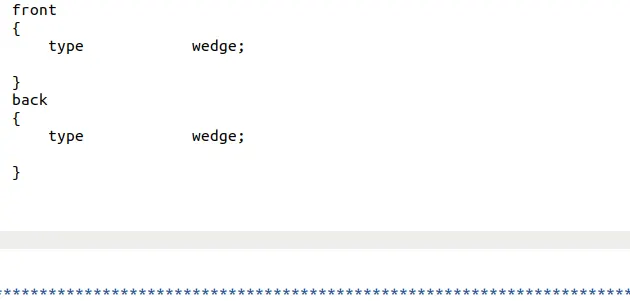
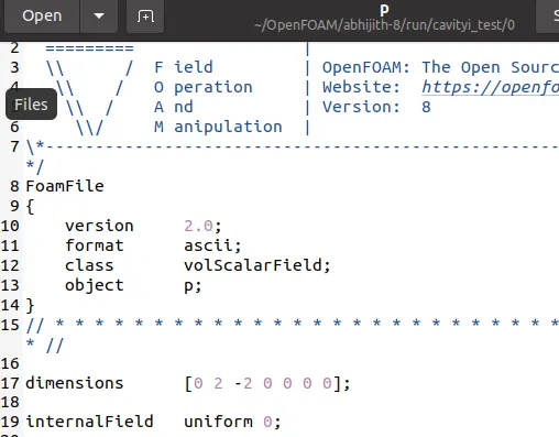
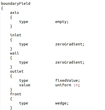
Pressure Feild 'P':
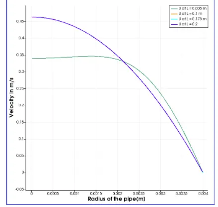
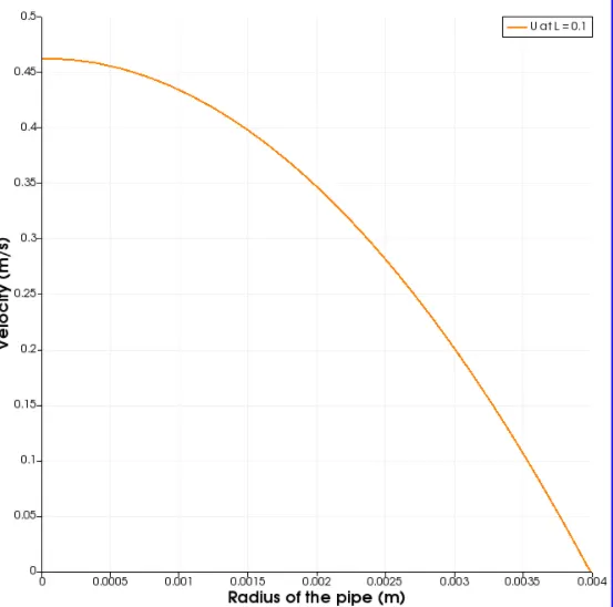
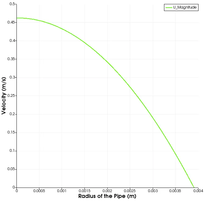
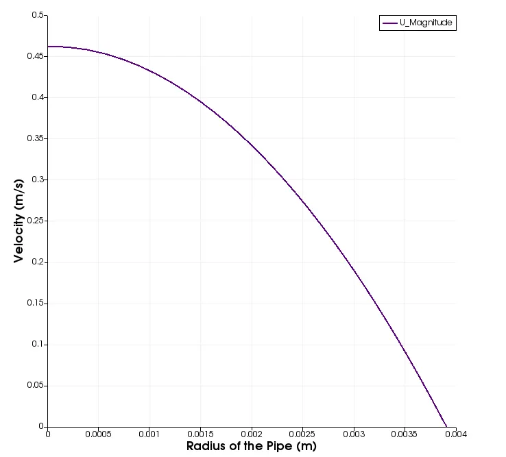
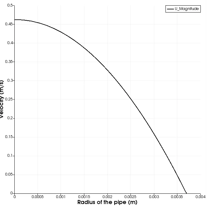
Velocity Variation:
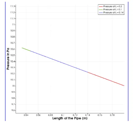
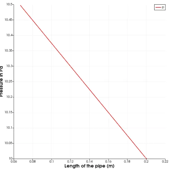
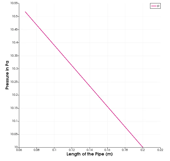
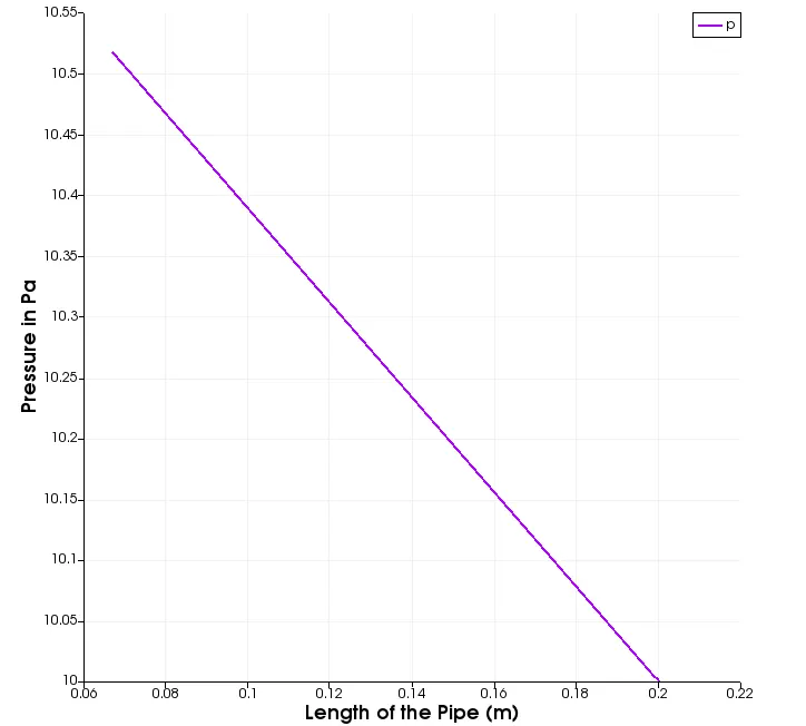
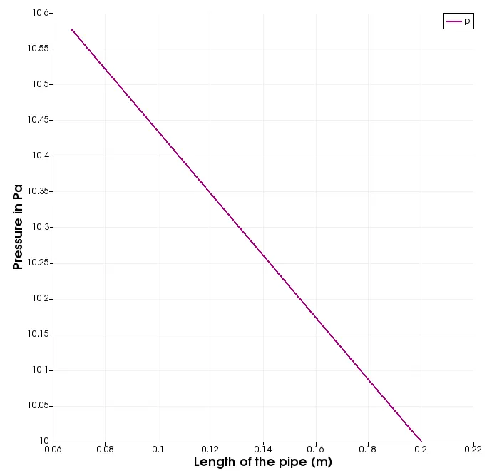
Pressure Variation:
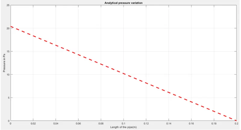
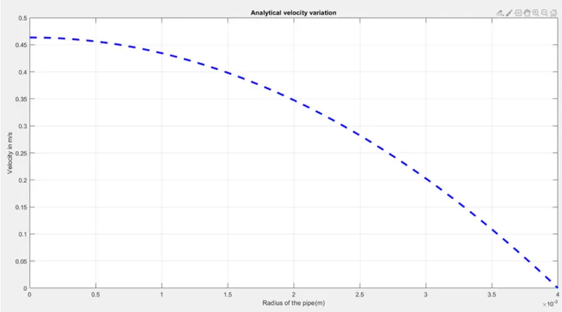
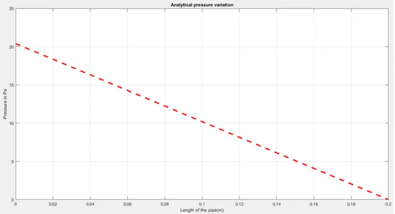
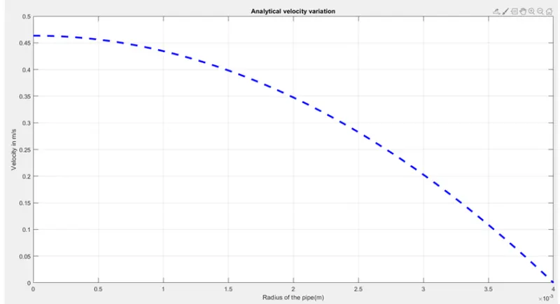
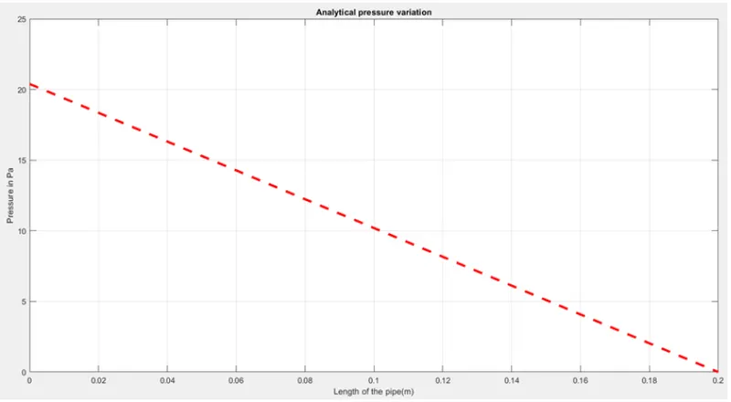
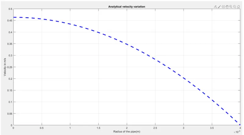
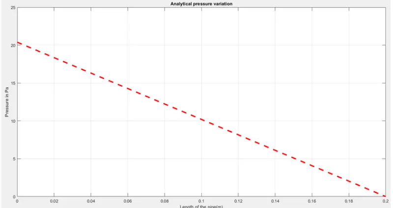
Validation using Matlab:
clear all
close all
clc

Q = 25.6e-6; %@inlet
L = 200e-3; %length of pipe
Re=2100; %reynolds number
D= 8e-3;
theta = 10;%angle of wedge
rho =997; %density
R=D/2;
mu= 8.8e-4; %dynamic viscosity
Lh =0.05*mu*D; %enterance length
nx=50;
ny=1;
nz=400;

file = blockMesh(R,theta,L,nx,ny,nz);
U_avg=(Re*mu)/(rho*D);
U_max=2*U_avg;

%velocity vector
r=linspace(0,R,1001);
U_r=2*U_avg*(1-((r.^2)/R^2));

%pressure vector
l=linspace(0,L,1001);
delta_Pr=(32*mu*l*U_avg)/(D^2);
P_r=fliplr(delta_Pr);
P_r=P_r';

%wall sgear stress
f=64/Re;
tau_wall=(f/4)*((rho*U_avg^2)/2);

%plotting
figure(1)
plot(r,U_r,'--b','linewidth',3);
xlabel('Radius of the pipe(m)');
ylabel('Velocity');
title('velocity variation');
grid on


figure(2)
plot(l,P_r,'--r','linewidth',3);
xlabel('Radius of the pipe(m)');
ylabel('pressure');
title('pressure variation');
grid on
Case 2: Symmetry BC:
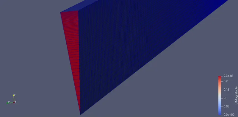
Velocity variation:
Pressure Variation:
Validation:
2) Simulation For 25 angle
Wedge Boundry:
Symmetry Condition:
Validation By Matlab:
3) Simulation of 45 angle:
wedge Boundry:
Symmetry condition:
Validation Matlab: