Week 12- Major Project (CFD Analysis on Combustion in a SCRAMJET engine)
The Scramjet engine design is an extension of the Ramjet. The difference between the two lies in flow state inside the engine. Both are designed to be used for supersonic flight, however a Scramjet allows the flow through the engine to remain supersonic, whereas in a Ramjet the flow is slowed to subsonic levels before it enters the combustor. Up to flight Mach numbers of 3 – 6 Ramjet engines are optimal. After Mach 6 various factors contribute to decreasing the efficiency of the engine. Slowing the flow to subsonic levels becomes unrealistic because this causes the combustor entrance temperature and pressure to become too high and causes the flow to dissociate. Combustion in dissociated flow is extremely inefficient because the heat released by exothermic combustion reactions is negated by the heat absorbed through endothermic dissociation reactions[1]
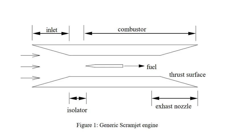
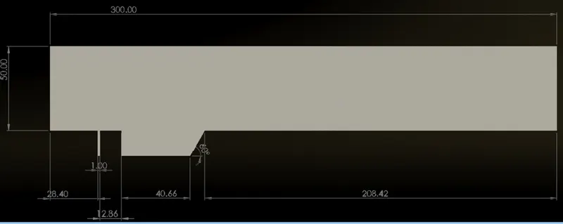
Geometry:
The geometry is created in spaceclaim with appropriate angle of cavity and geometry is converted to surface with pull tool
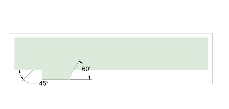
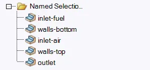
named sections to be:
Mesh:
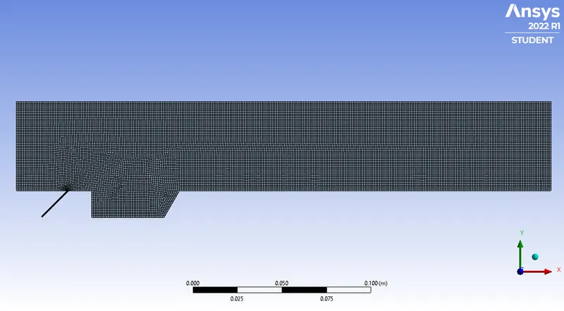
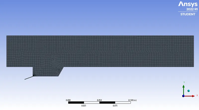
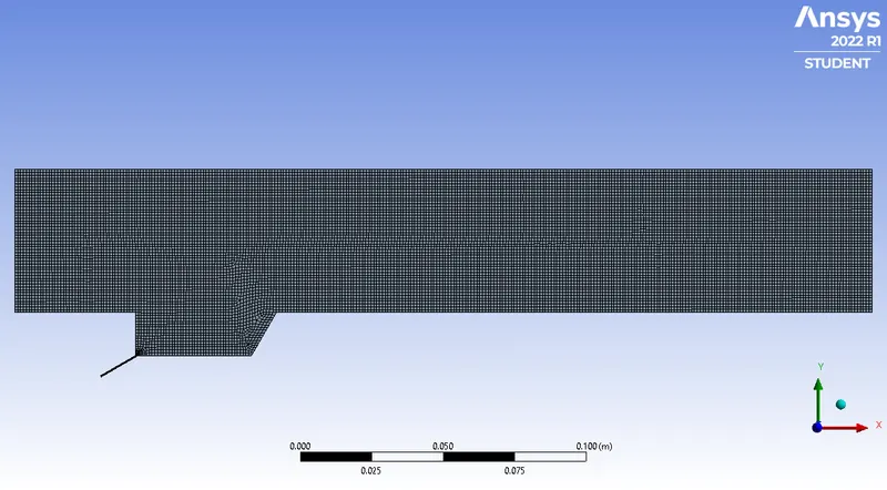
Quadilateral mesh is used because its 2d simulation and mesh is more refined at fuel injector section
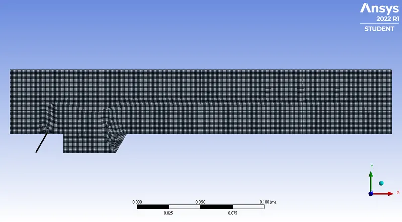
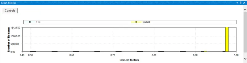
Mesh is good as mesh elements is above 0.8
Setup:
General:
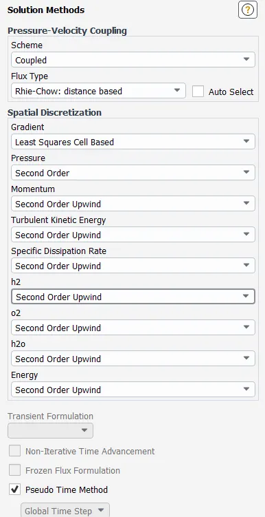
- Pressure based
- staedy state solver
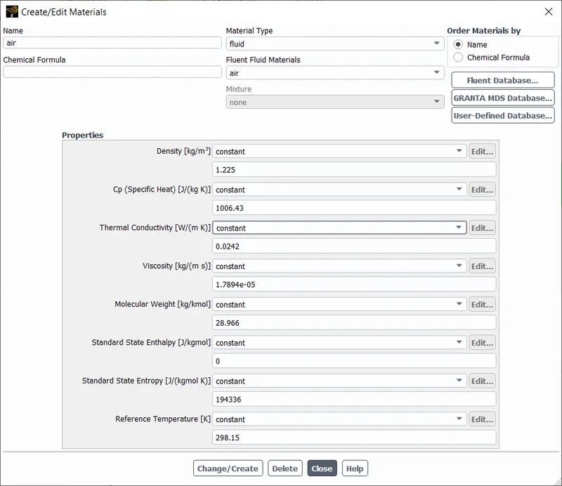
Materials:
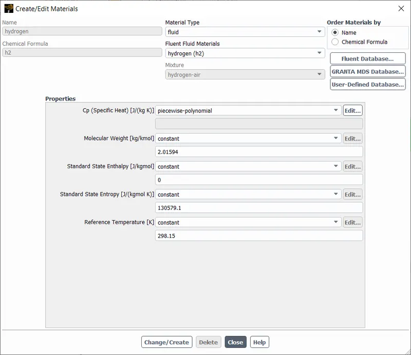
H2,
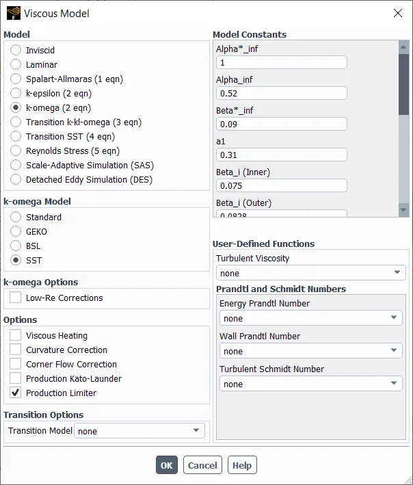
Turbulence Model:
Most used model from LR : K-epsilon and K-omega
But due to flexibility of K-epsilon ,going to apply it in simmulations
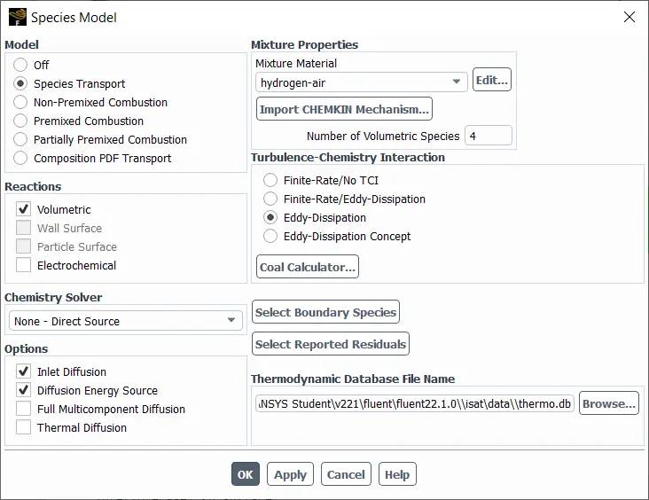
Boundry Conditions[2]:
- inlet-air - velocity-inlet, 1040 m/s velocity, 600K temperature, and O2
with a mole fraction of 0.21 (to simulate atmospheric air).
- inlet-fuel - velocity-inlet, 200m/s
velocity, 500 bar pressure (5×10⁷Pa), and H2O
with a mole fraction of 1 (pure hydrogen).
- outlet - pressure-outlet, 0Pa.
walls-bottom, walls-top - stationary wall.
Boundry Conditions:
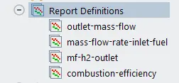
outlet-mass-flow - this report generates the mass flow rate at the outlet.
mass-flow-rate-inlet-fuel - this report generates the mass flow rate of the fuel at the inlet.
mf-h2-outlet - this generates the mass fraction of fuel at the outlet.
combustion-efficiency - this generates the combustion efficiency at the outlet
Results:
QUalitative REsults:
Temperature :
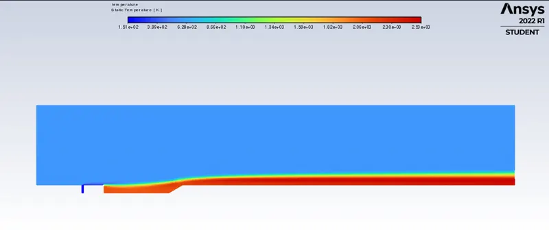
The combustion produces heat, most of the heat is generated in the cavity. This is expected as the cavity is designed for this purpose.
O2 Contour
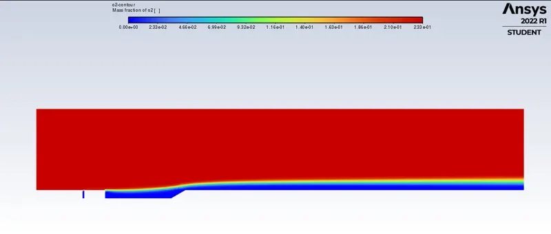
There is no oxygen present in the fuel inlet and in the cavity, this means that combustion has taken place in the cavity. Oxygen is presnet in the gap between fuel inlet and cavity, this also says that fuel does not immediately combust after entering the freestream.
H2 Contour
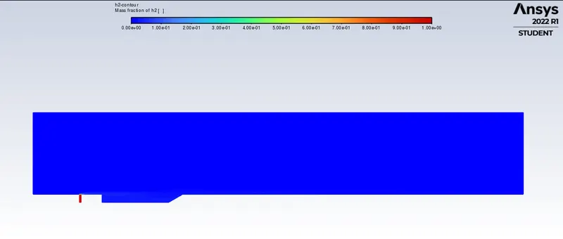
All of the hydrogen fuel dissolves immediately after entering the freestream flow, this is because the fuel ratio is extremely low for this simulation (as only 1 fuel inlet is being simulated). The fuel ratio is about 0.001.
H2O Contour
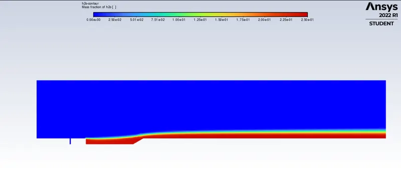
Water is a byproduct of the combustion reaction is so only seen to be generated in the cavity, this confirms that combustion takes place only in the cavity and not anywhere else.
Case 1:
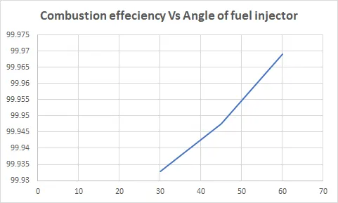
Angle of cavity: 30° Fuel Injector Angle: 90°
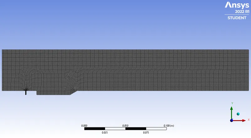
Number of iterations: 115
Combustion Efficiency: 0.99932903
Angle of cavity: 45° Fuel Injector Angle: 90°
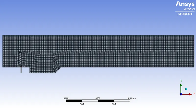
Number of iterations: 167
Combustion Efficiency: 0.99947512
Case 2:
Angle of cavity: 60° Fuel Injector Angle: 20°
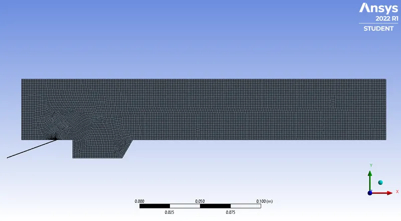
Number of Iterations: 106
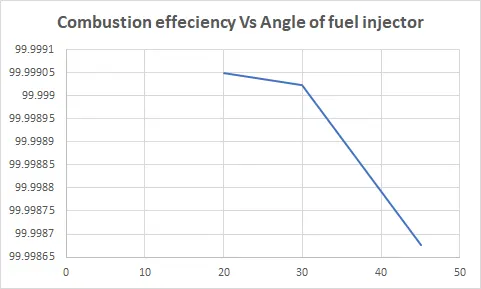
Combustion Efficiency: 0.99999005
Angle of cavity: 60° Fuel Injector Angle: 30°
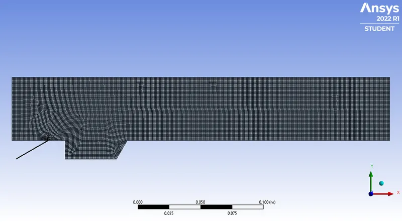
Number of Iterations: 113
Combustion Efficiency: 0.99999022
Angle of cavity: 60° Fuel Injector Angle: 45°
Number of Iterations: 200
Combustion Efficiency: 0.99998677
Case 3:
Angle of cavity: 60° Fuel Injector Angle: 20°
Number of Iterations: 170
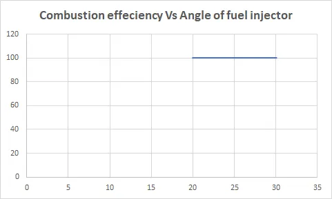
Combustion Efficiency: 1
Mass Fraction of H2 at outlet: 1.1043768e-10
2. Angle of cavity: 60° Fuel Injector Angle: 30°
Number of Iterations: 114
Combustion Efficiency: 1
Mass Fraction of H2 at outlet: 3.4076226e-09
3. Angle of cavity: 45° Fuel Injector Angle: 20°

Number of Iterations: 166
Combustion Efficiency: 1
Mass Fraction of H2 at outlet: 1.0374389e-10
Summary:
Case 1: (Fuel Injector Angle: 90°)
| Angle of Fuel Injector | Combustion% | Iteration |
| 30 | 99.932903 | 114 |
| 45 | 99.947512 | 166 |
| 60 | 99.969113 | 200 |
Case 2: (Angle of Cavity: 60°)
| Angle of Fuel Injector | Combustion% | Iteration |
| 20 | 99.99905 | 106 |
| 30 | 99.999022 | 113 |
| 45 | 99.998677 | 201 |
Case 3:
| Angle of Fuel Injector | Combustion% | Iteration | Angle of Cavity |
| 20 | 100 | 170 | 60 |
| 30 | 100 | 114 | 60 |
| 20 | 100 | 167 | 45 |
COnclusion:
- The simulation was performed according to the objectives
- The efficiency increases as the cavity angle increases, this can be due to increased area during combustion when the angle of cavity is increased.
- The fuel injector angle provides the least resistance to flow/combustion and cavity angle provides the most space for complete combustion
Reference:
[1]: Peter Hyslop, CFD MODELLING OF SUPERSONIC COMBUSTION IN A SCRAMJET ENGINE
[2]: Fuhua & Yang,Dynamic Combustion Characteristics in Scramjet Combustors with Transverse Fuel Injection.