Week 7 - Minor Project
Aim
The major objective of this simulation was to set a simulation over the NACA 2412 aerofoil with different angles of attack(AOA) using Converge CFD and estimating its coefficient of lift and drag.
Introduction:
Airfoil is a structure that provides required Lift force and Drag force depending on profile design i.e. curved surface when an Airfoil structure moved in a fluid medium, it provides the aerodynamic forces. Therefore it is quite important to understand the importance behind the shape of Airfoil. As CFD is a powerful tool used to carry out the simulation by considering the real-life behavior of the fluid. In this study, the main objective is to carry out a detailed study on lift and drag coefficients of NACA2412 Airfoil sections with different AOA. Setting up the simulation in Converge CFD studio, solving it using Cygwin, and post-processing the contour plots using ParaView.
| Angle Of Attack (AOA) | 1∘">1∘1∘ | 5∘">5∘5∘ | 10o">10o10o | 15o">15o15o |
Aerofoil: Terminology and Definitions
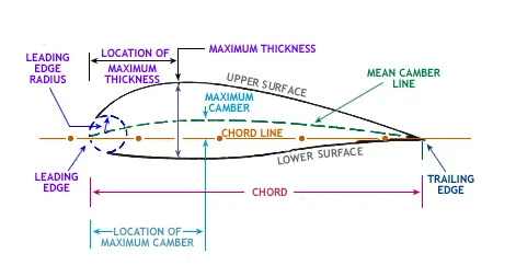
Aerofoil sketch is shown in Figure, which illustrates terminology:
1. Mean camber line- A line drawn halfway between the upper and lower surfaces of the aerofoil.
2. Leading-edge- It is the front edge of aerofoil where maximum curvature can be found.
3. Trailing edge- It is the rearmost edge of an aerofoil.
4. Chord line- It is the connecting line between leading and trailing edge and it is straight.
5. Chord length- It is the length of the chord line.
6. Camber- It is the maximum perpendicular distance between the mean camber line to chord line.
7. Thickness- It is measured either perpendicular to the camber line or perpendicular to the chord line.
8. The angle of attack- It is defined as the angle between the chord line and the relative wind or flight path.
Nomenclature of NACA-4 Digit Aerofoil
The NACA four-digit aerofoil sections define the profile by:
The first digit provides maximum camber which is in the percentage of the total chord length.
The second digit provides the distance of maximum camber from the leading edge in tens of percent of the total chord length.
The last two digits describe the maximum thickness of the aerofoil as a percentage of the total chord length.
For example, NACA 2415 aerofoil has a total chord length of 100 mm. So aerofoil has maximum camber 2mm which is 40mm far from leading edge with 15mm thickness.
Lift coefficient (CL)- It is a dimensionless coefficient that relates the lifting force on the body to its velocity, surface area, and the density of the fluid in which it is lifting.
Lift force - It is a force that is perpendicular to the relative wind.
Lift Force=12⋅Cl⋅ρ⋅A⋅V2">Lift Force=`1/2*C_l*rho*A*V^2`ρ=1.766kgm3
Drag coefficient (Cd)- It is a dimensionless coefficient that relates the dragging force on the body to its velocity, surface area, and the density of the fluid in which it is moving.
Drag force - It is a force that is parallel to the relative wind.
Drag Force=12⋅Cd⋅ρ⋅A⋅V2">Drag Force=`1/2*C_d*rho*A*V^2`μ=0.00001846kgms
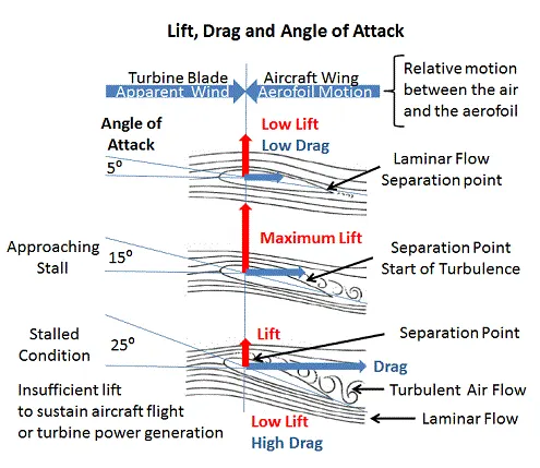
At very low angles of attack, the airflow over the aerofoil is essentially smooth and laminar with perhaps a small amount of turbulence occurring at the trailing edge of the aerofoil. The point at which laminar flow ceases and turbulence begins is known as the separation point.
Increasing the angle of attack increases the area of the aerofoil facing directly into the wind. This increases the lift but it also moves the separation point of laminar flow of the air above the aerofoil part way up towards the leading edge and the result of the increased turbulent flow above the aerofoil is an increase in the drag.
A maximum lift typically occurs when the angle of attack is around 15 degrees but this could be higher for specially designed aerofoils.
Above 15 degrees, the separation point moves right up to the leading edge of the aerofoil and laminar flow above the aerofoil is destroyed. The increased turbulence causes the rapid deterioration of the lift force while at the same time it dramatically increases the drag, resulting in a stall.
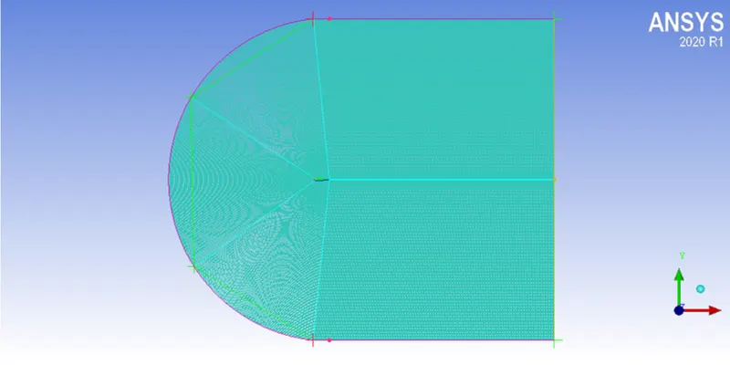
1.Geometry Creation
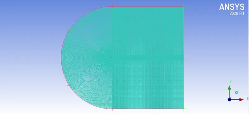
Import the mesh file from ICEM CFD to mesh
- For compressible:
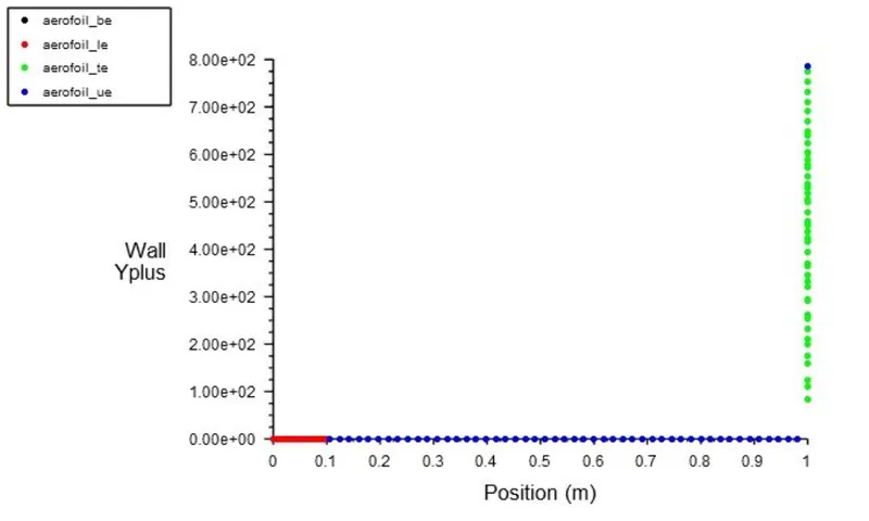
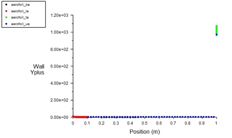
Y plus:
For Incompressible:
Fluent Setup:
General:
- Steady-state, absolute velocity, PRessure based ,planner
Boundries:
Inlet-velocity specifications method:Components
Outlet-0 gauge pressure
Turbulence models:
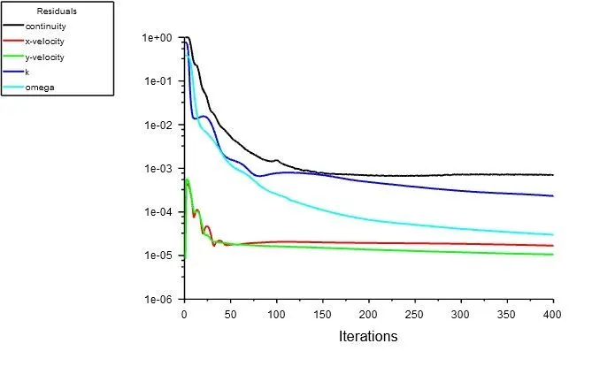
K-omega SSt model
Post Processing:
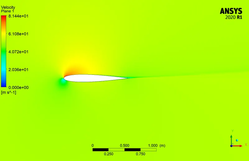
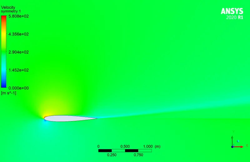
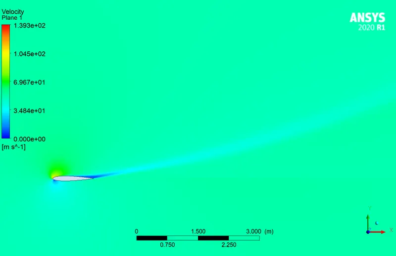
- Velocity Contour
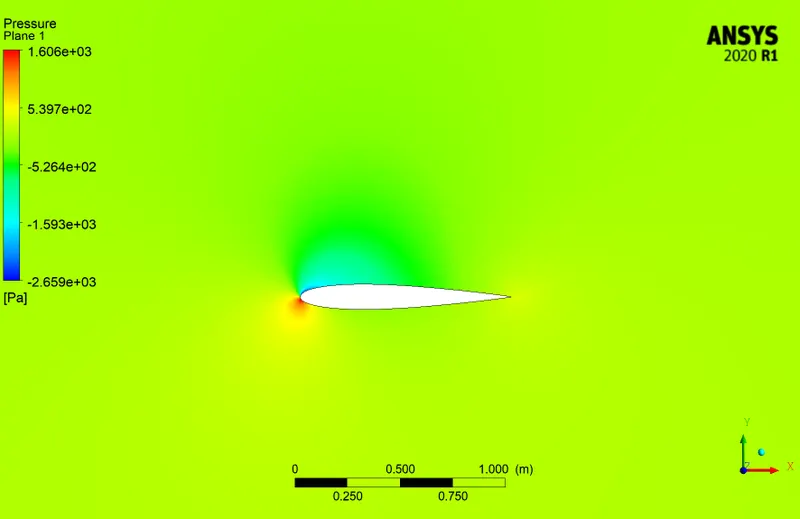
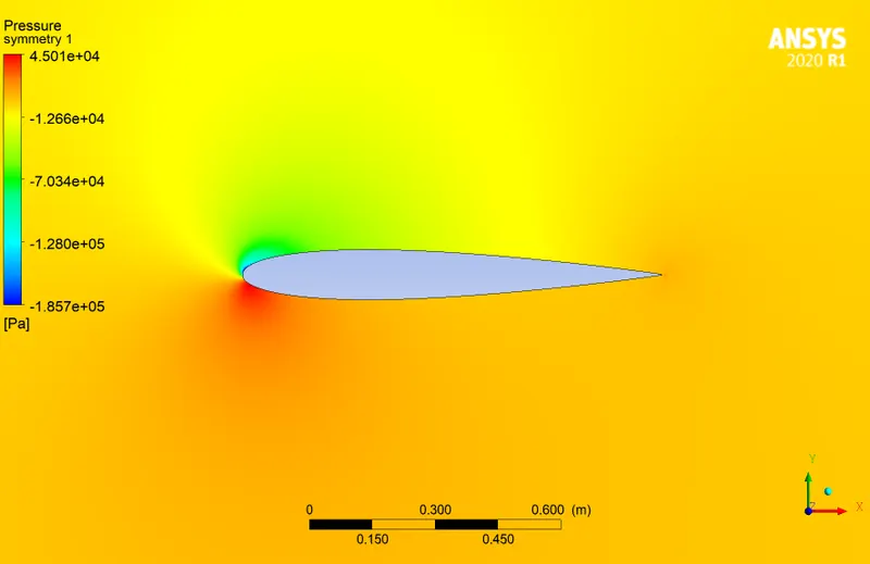
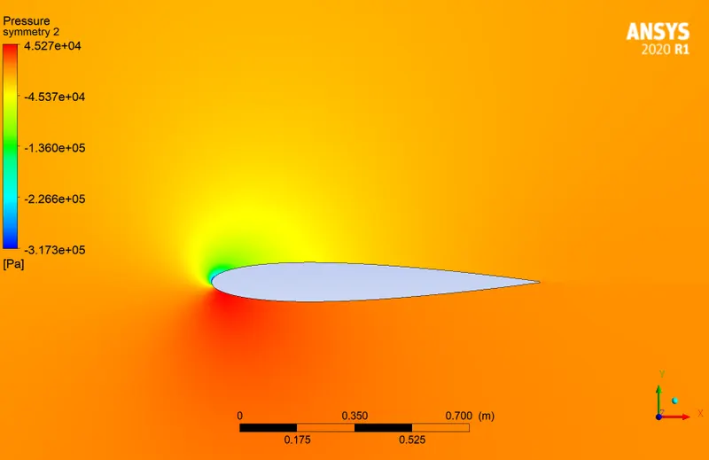
- Pressure Contour
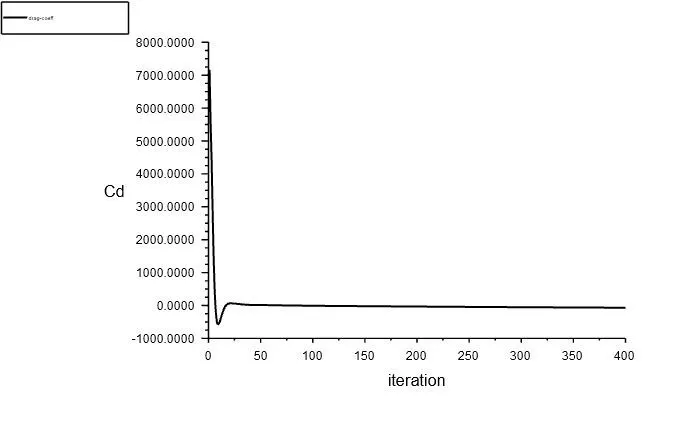
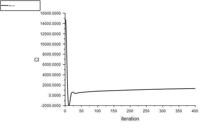
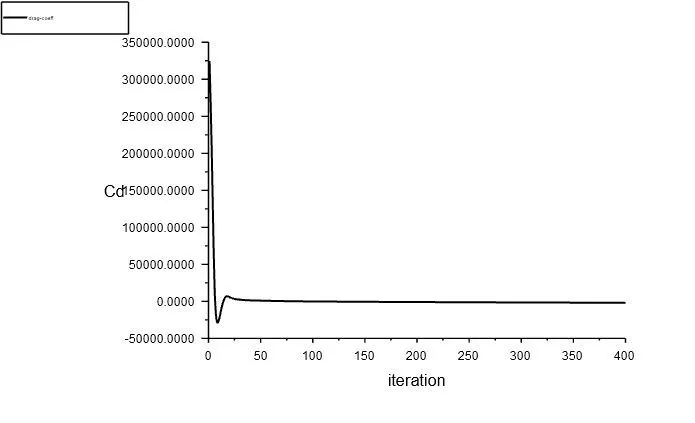
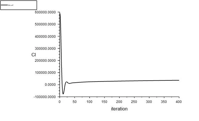
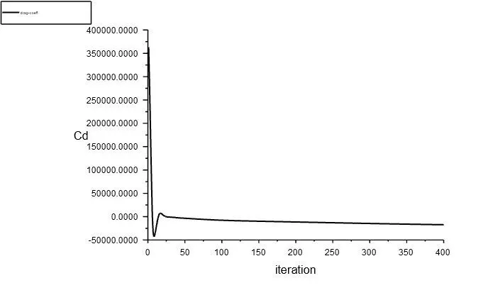
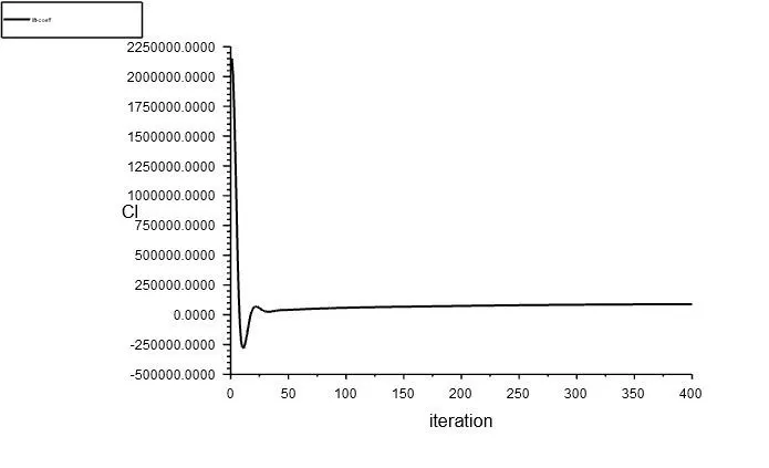
- Coeffecient Of drag and lift
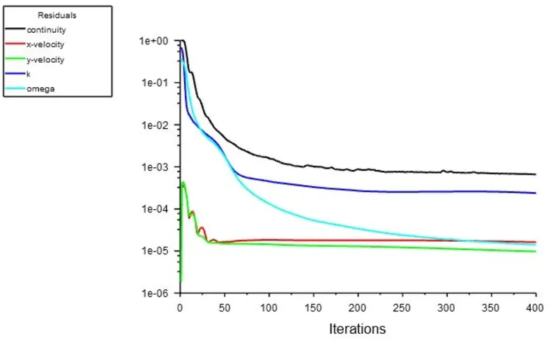
Time step:400 Time step size:1
Result:
1)AOA=5:
1.1).Incompressible
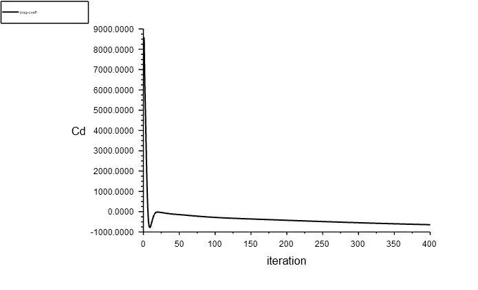
Drag:
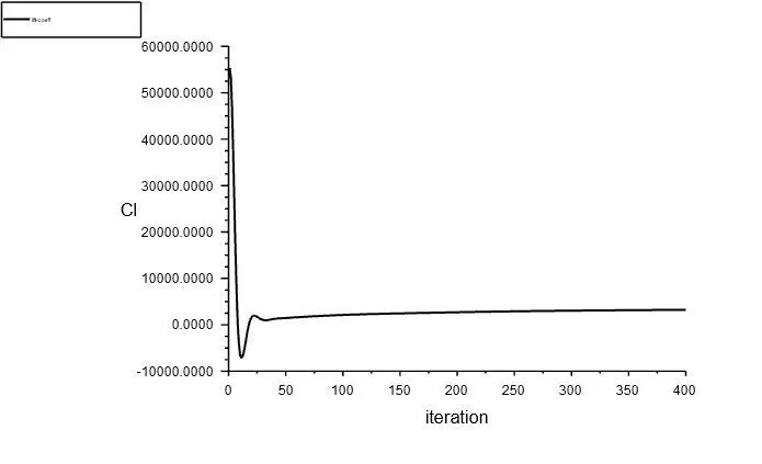
Lift:
1.1) Compressible
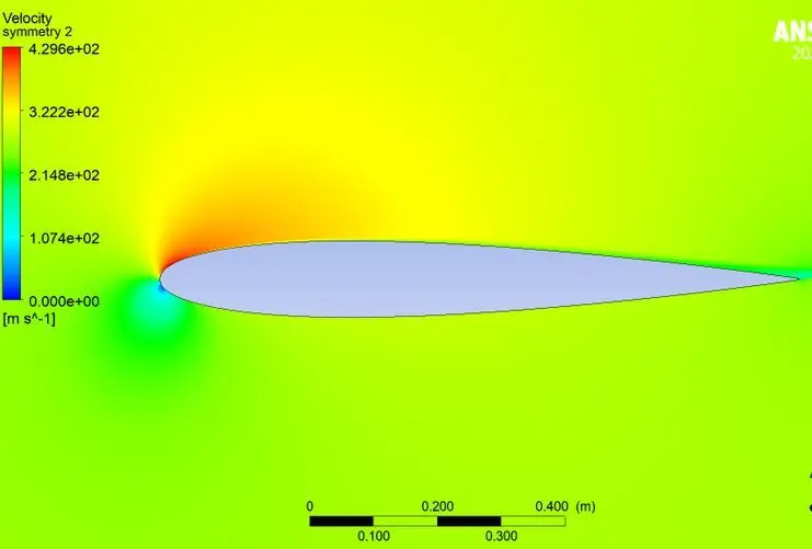
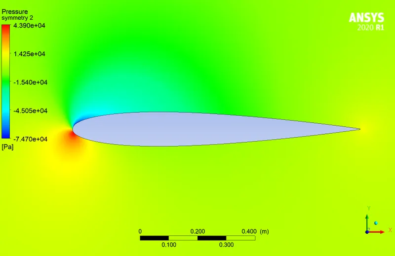
Drag
Lift
2)AOA 10
2.1) Incompressible
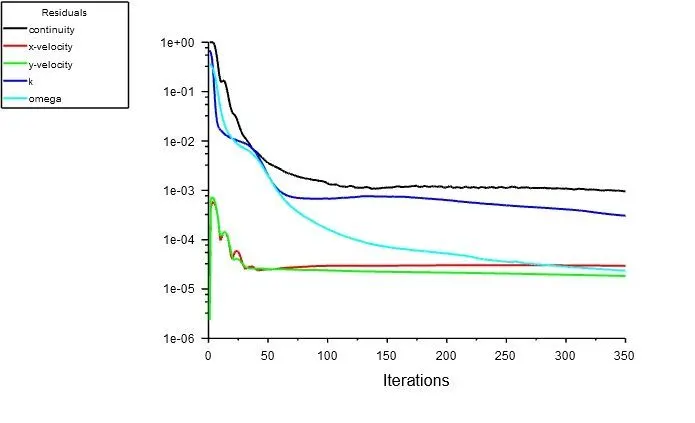
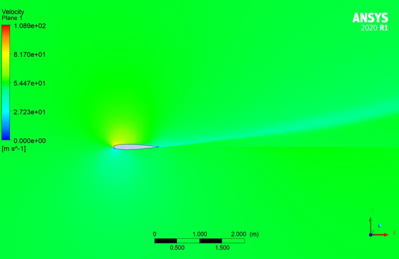
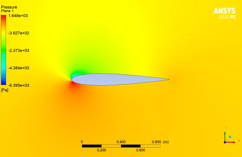
Drag:
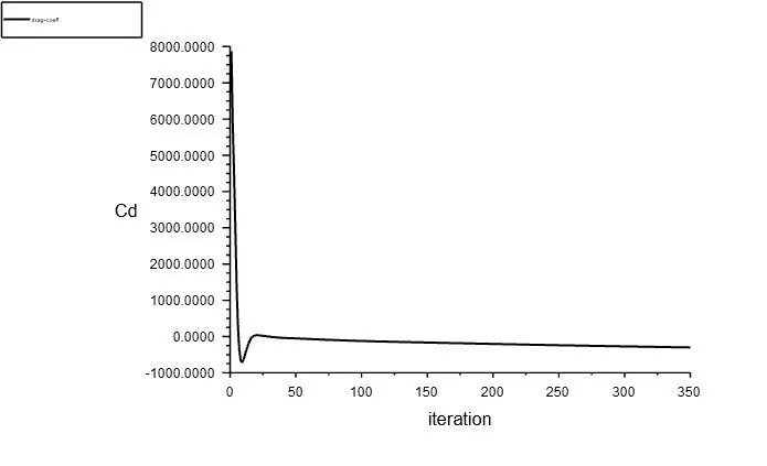
Lift:
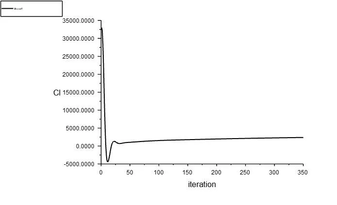
2.2) Compressible
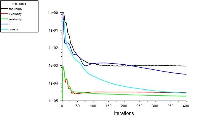
Drag:
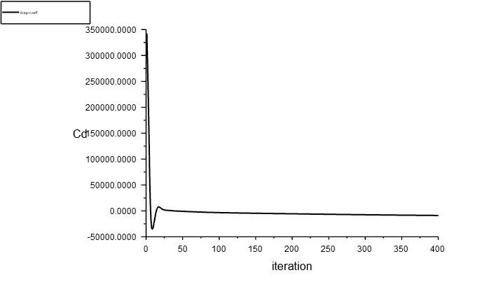
Lift:
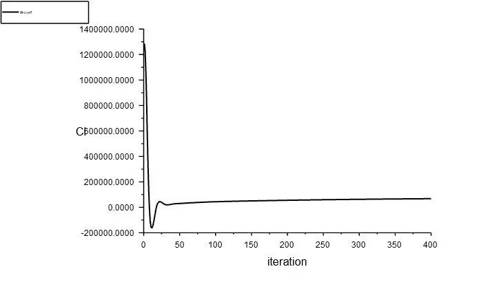
3) AOA=15
3.1) Incompressible:
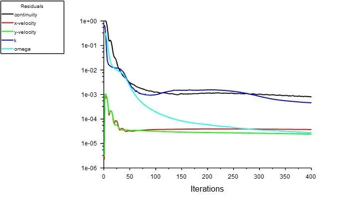
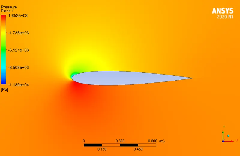
Drag:
Lift:
3.2) Compressible
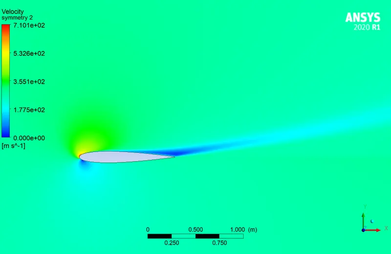
Drag:
Lift:
Conclusion
- At higher speed and maximium AOA 15 ,maximum lift is produced
- Fluid velocity increases over the airfoil
- At slat region maximum velocity is obtained