Week 12- Final project
AIM:To develop the Car Door Trim Panel of a car using CATIA V5 by Using the Class A surface and Master sections as input.Create the Solid body and Design the engineering features like Heatsteak,Locators,Flanges,Doghouse and attach the push pin.
Components in Door Trim panel,
- Arm Rest
- Upper Map
- Lower Map Pocket
- Lower Substrate
INTRODUCTION:
- Car Door panel
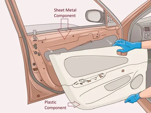
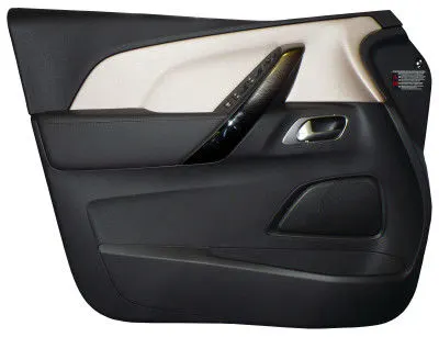
Door panels serve as an interface between the interior of the car and the inner workings of the door, and between vehicle occupants and the door.Modern cars typically have door cards made of plastic, most often using injection moulding, as well as incorporating other decorative materials.They are expected to meet a variety of design specifications regarding safety, aesthetics, and functionality. In addition, they are expected to continue the material theme of the dashboard and pillars while concealing intricate electrical and mechanical components for operating locks, windows, and other features. The door panel has evolved from a simple two-part system of latch and simple winding mechanism to a more sophisticated enclosure. Doors currently have an inner full-width panel consisting of electronic windows, central locking system, and speakers. These panels typically consist of a foamed core covered with either textiles or plastics.
- Role of plastics in the Automotive Industry
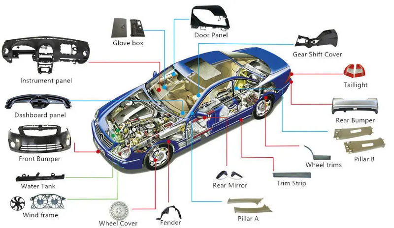
The role of plastic in the design and manufacturing of automotive vehicles has never been more essential, with stringent regulations and changing consumer habits driving demand for more affordable, lightweight, and fuel-efficient vehicles. Fuel efficiency has become one of the most important features in automotive vehicle design due to the rising fuel prices and stricter environmental regulations.There are about 30,000 parts in a vehicle, out of which 1/3 are made of plastic. In total, about 39 different types of basic plastics and polymers are used to make an automobile. More than 70% of the plastic used in automobiles comes from four polymers: polypropylene, polyurethane, polyamides and PVC. Plastic has become one of the key materials required for the structure, performance, and safety of automobiles in recent years, with growth in plastic consumption being driven by light-weighting trends for fuel efficiency and consequently lower greenhouse gas emissions.
- Manufacturing Process:
Injection Moulding:
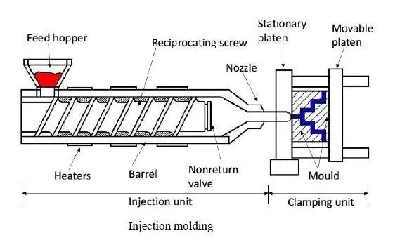
njection moulding is one of the most commonly used production processes for plastics. It offers a viable solution for the mass production of high-quality injection automotive parts from a broad range of polymers. In the automotive industry, where consistency, safety, and quality are of utmost importance, automotive plastic injection moulding is an important manufacturing process.
Plastic injection moulding is the process of melting plastic pellets that once malleable enough, are injected at pressure into a mould cavity, which fills and solidifies to produce the final product.
Tooling Direction
Tooling direction is the direction the mould takes to make the part. It is basically the direction that the mould pulls apart. The mould is built in two separate pieces, a cavity side and the core side. The core pulls apart from the cavity and that is the Tooling Direction.
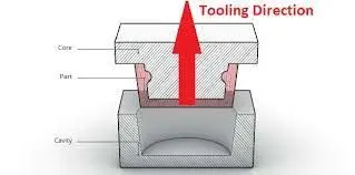
Core is the male part which forms the internal shape of the moulding. Cavity is the female part that forms the external shape of moulding.
Parting line is the line of separation core and cavity.
- Engineering Features:
Heatsteak
Heat steak is used to join the plastic components permanently.Heat staking technology is quite simple in concept. Whenever two or more components need to be attached to one another, and at least one is made of a thermoplastic, a combination of heat and pressure can be used to reform the plastic to the many shapes or profiles to retain or join the parts together.
Locators
Locators are used to restricts motion.
A 2-way locating pin restricts motion along 1 axis (or 2 degrees of Freedom), like a round pin in a slot. Likewise, a 4-way pin restricts 4 degrees of freedom along 2 axes.
Doghouse
Dog house is an engineering feature used in plastic trim design. Dog houses are used as supporting feature. Sometimes other engineering features like snaps; locators etc. are mounded on them to increase their strength.
Flanges
A plastic flange provides the connection between two components.
OBJECTIVE:
- Improve the Class A surface.
- To create a tooling direction.
- To perform draft analysis.
- To design the B-Surface and C-Surface using the given Class-A surface.
- Thicken the component.
- Create the Engineering features while following the given Design Guidelines.
- CLASS A SURFACE
Given Class A surface of DOOR TRIM
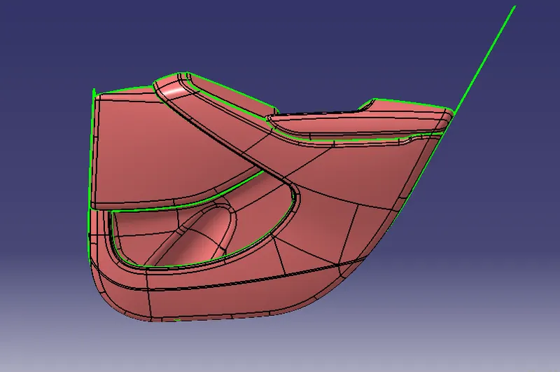
Check the class A surface .If any discontinuity in that improve the class A.Then create Tooling axis ,check Draft analysis and Create Solid Body.
- ARM REST
Class A Surface
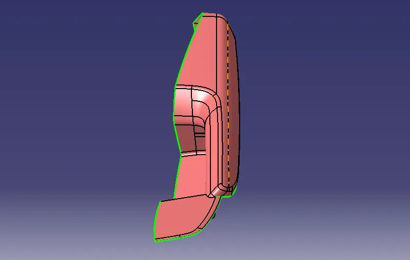
Given class A having some Discontinuity.
Improved Class A
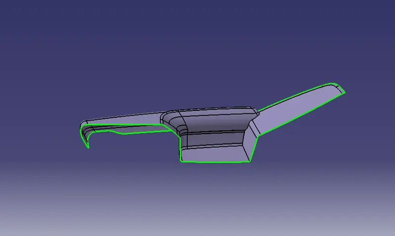
Tooling Axis
observe the given class-A surface and find the proper surface to create Tooling axis,
- Extract and Create a Point on Surface.
- Draw a Point-diraction line through that point along z .
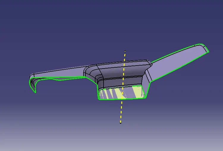
Side core axis
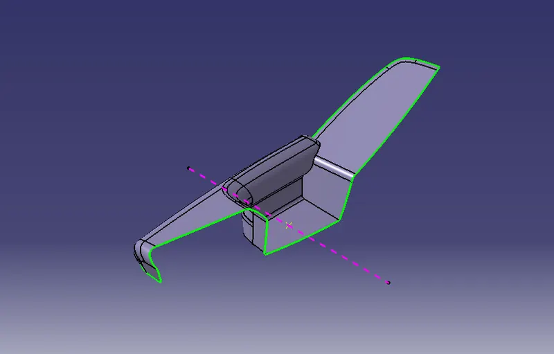
Draft Analysis of Class A
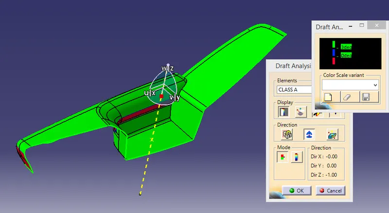
Draft analysis for the given CLASS-A surface,
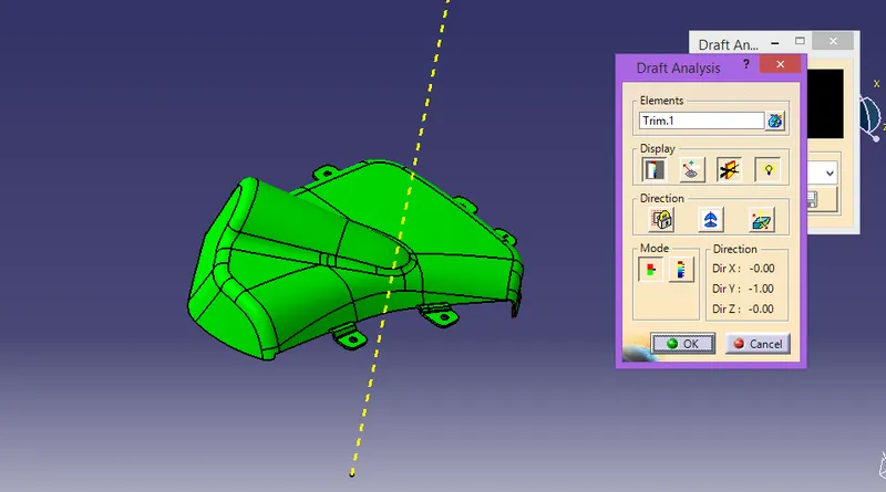
Draft analysis is done after determining the tooling axis, draft analysis is used to check whether the minimum draft (3 degrees) is maintained or not.
- Open the featured draft analysis tool.
- Drag and align the compass on the Tooling axis.
Lock the draft direction and perform draft analysis by clicking on the component
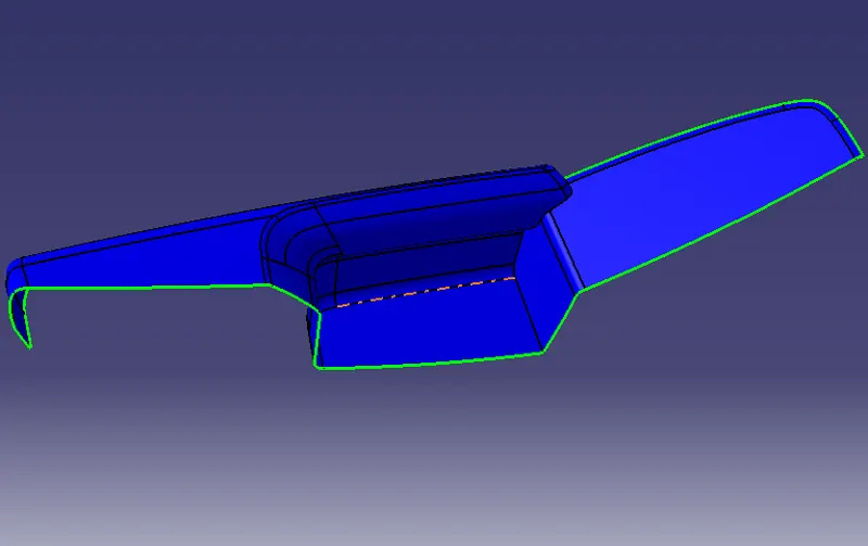
Class B surface
Class B Surface is created With the help Class A Surface
- Offset the class-A surface to 2.5mm inward direction.
- Remove patches and discontinuity of the offset surfaces using the features like extract, multi-extract,Un trim, extrapolate.
- Provide proper Fillets and Join.
To ensure there is no gap in Class-B surfaces ,check the boundary command to find out the boundary
Class C surface
Class C is created with help of A-Surface,The Surface that joins class-A and class-B surfaces.
- Create the Boundary.
- Sweep command with Reference Surface & With Draft Direction.
Extrapulate Edges & Trim.
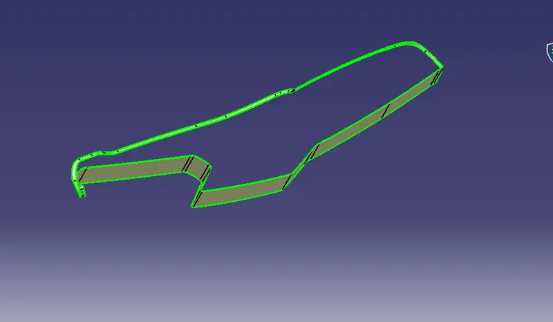
Final Trim
- Join A+C surface
- Trim A+C with B surface.
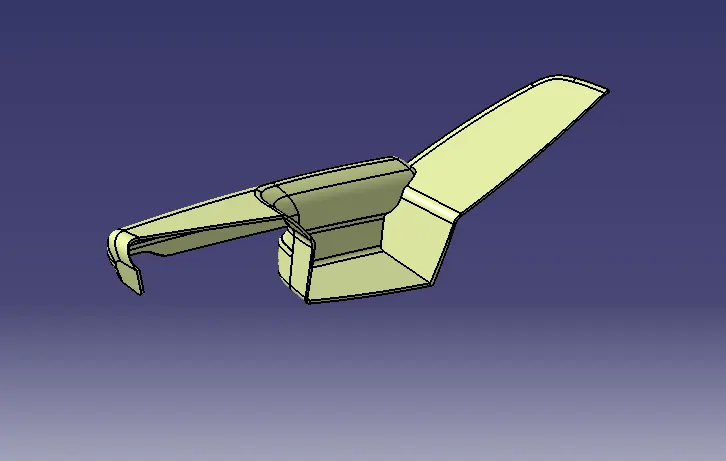
In part design work bench and using the close surface command create the part as solid part body.
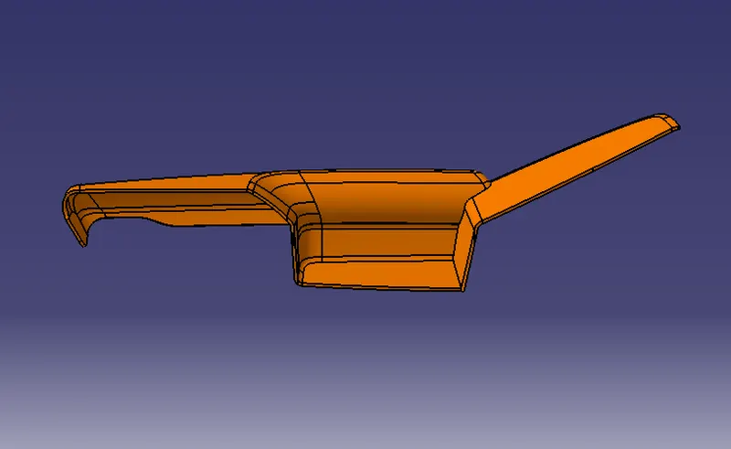
- LOWER SUBSTRACT
Class A Surface
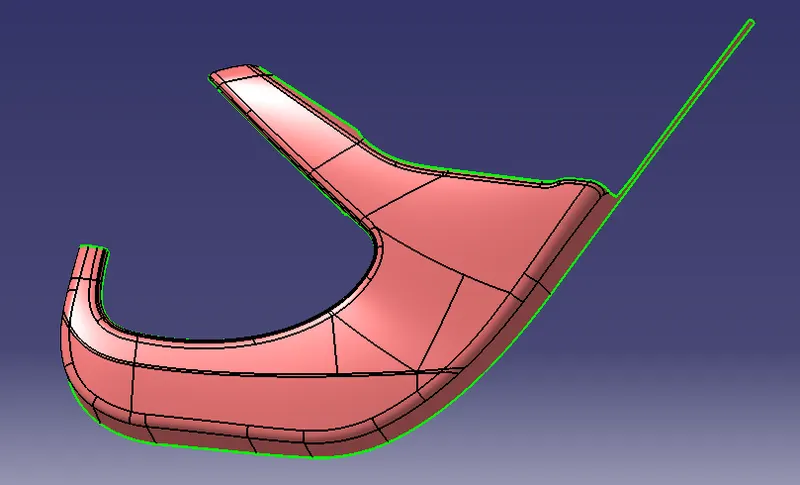
Tooling Axis
observe the given class-A surface and find the proper surface to create Tooling axis,
- Create a point on curve
- Draw a Point-diraction line .
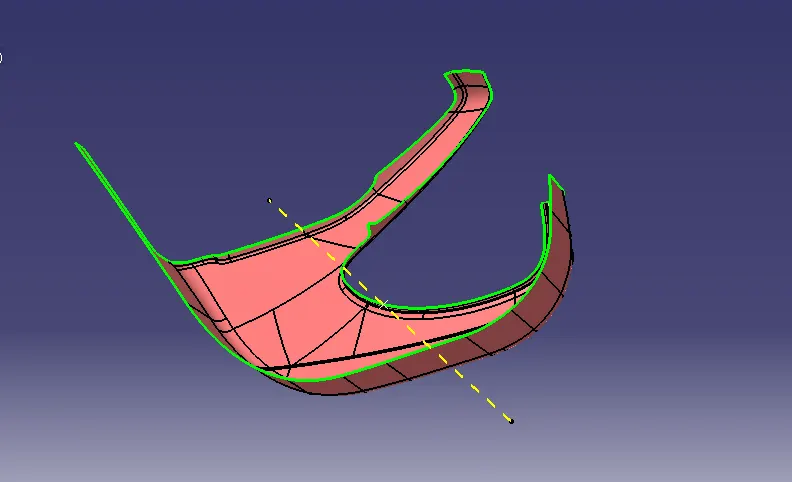
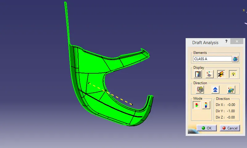
Draft Analysis of class A
Draft analysis for the given CLASS-A surface,
Draft analysis is done after determining the tooling axis, draft analysis is used to check whether the minimum draft (3 degrees) is maintained or not.
- Open the featured draft analysis tool.
- Drag and align the compass on the Tooling axis.
Lock the draft direction and perform draft analysis by clicking on the component
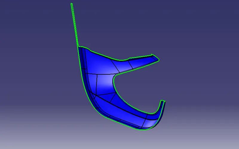
Class B surface
Class B Surface is created With the help Class A Surface
- Offset the class-A surface to 2.5mm.
To ensure there is no gap in Class-B surfaces ,check the boundary command to find out the boundary.
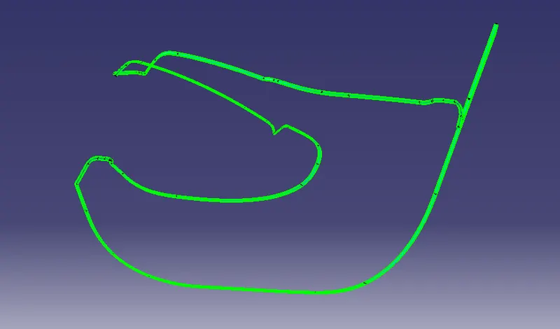
Class C surface
Class C is created with help of A-Surface,The Surface that joins class-A and class-B surfaces.
- Create the Boundary.
- Sweep command with Reference Surface & With Draft Direction.
Extrapulate Edges & Trim.
Final Trim
- Join A+C surface
- Trim A+C with B surface.
In part design work bench and using the close surface command create the part as solid part body.
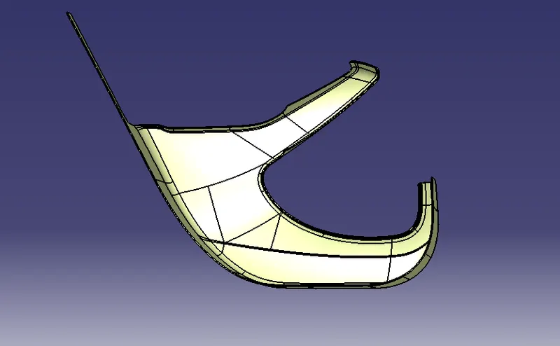
- BOTTEL HOLDER
Class A Surface
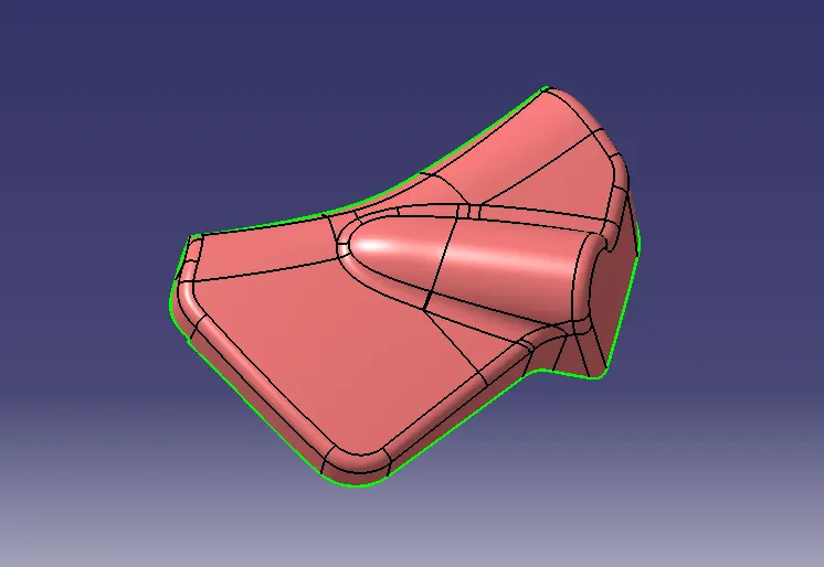
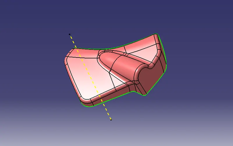
Tooling Axis
observe the given class-A surface and find the proper surface to create Tooling axis,
- Extract and Create a Point on Surface.
- Draw a Point-diraction line.
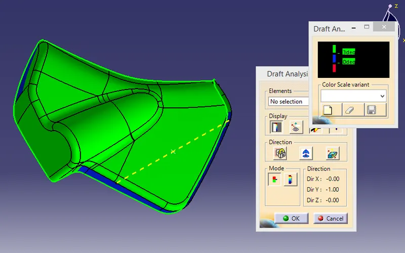
Draft Analysis of Class A
Draft analysis for the given CLASS-A surface,
Draft analysis is done after determining the tooling axis, draft analysis is used to check whether the minimum draft (3 degrees) is maintained or not.
- Open the featured draft analysis tool.
- Drag and align the compass on the Tooling axis.
Lock the draft direction and perform draft analysis by clicking on the component
Class B surface
Class B Surface is created With the help Class A Surface
- Offset the class-A surface to 2.5mm.
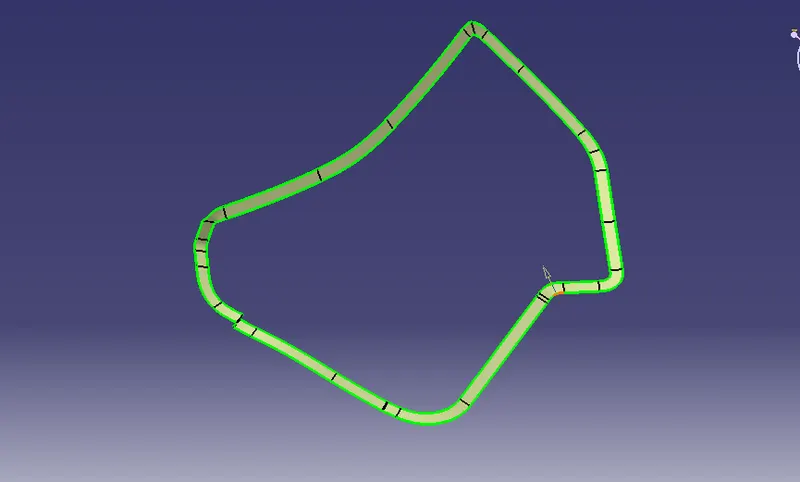
To ensure there is no gap in Class-B surfaces ,check the boundary command to find out the boundary.
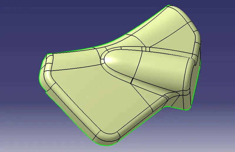
Class C surface
Class C is created with help of A-Surface,The Surface that joins class-A and class-B surfaces.
- Create the Boundary.
- Sweep command with Reference Surface & With Draft Direction.
Extrapulate Edges & Trim.
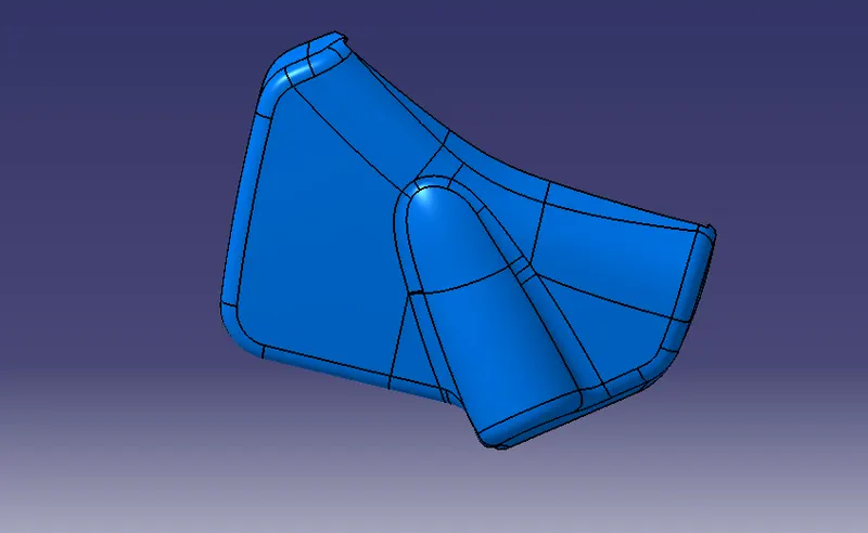
Solid Body
- Join A+C surface
- Trim A+C with B surface.
In part design work bench and using the close surface command create the part as solid part body.
- MAP POCKET
Class A Surface
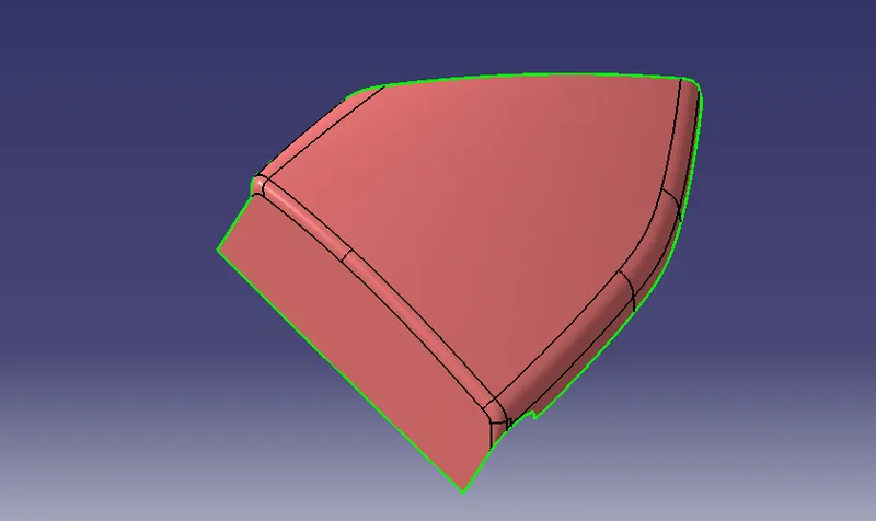
Tooling Axis
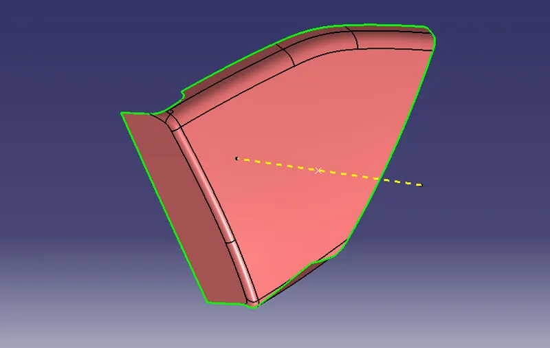
Draft Analysis of Class A
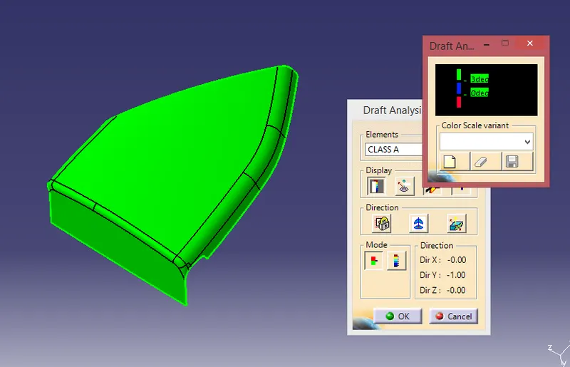
Draft analysis for the given CLASS-A surface,
Draft analysis is done after determining the tooling axis, draft analysis is used to check whether the minimum draft (3 degrees) is maintained or not.
- Open the featured draft analysis tool.
- Drag and align the compass on the Tooling axis.
Lock the draft direction and perform draft analysis by clicking on the component
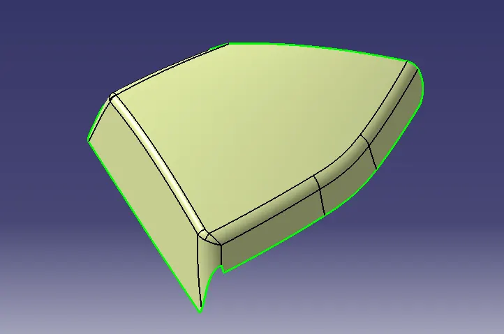
Class B Surface
Class B Surface is created With the help Class A Surface
- Offset the class-A surface to 2.5mm inward direction.
- Remove patches and discontinuity of the offset surfaces using the features like extract, multi-extract,Un trim, extrapolate.
- Provide proper Fillets and Join.
To ensure there is no gap in Class-B surfaces ,check the boundary command to find out the boundary.
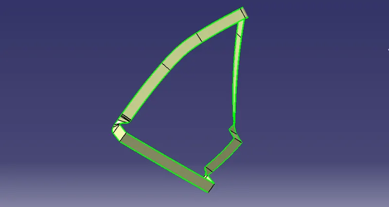
Class C Surface
Class C is created with help of A-Surface,The Surface that joins class-A and class-B surfaces.
- Create the Boundary.
- Sweep command with Reference Surface & With Draft Direction.
Extrapulate Edges & Trim.
Solid Body
- Join A+C surface
- Trim A+C with B surface.
In part design work bench and using the close surface command create the part as solid part body.
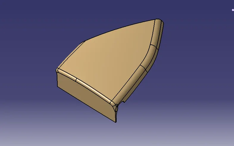
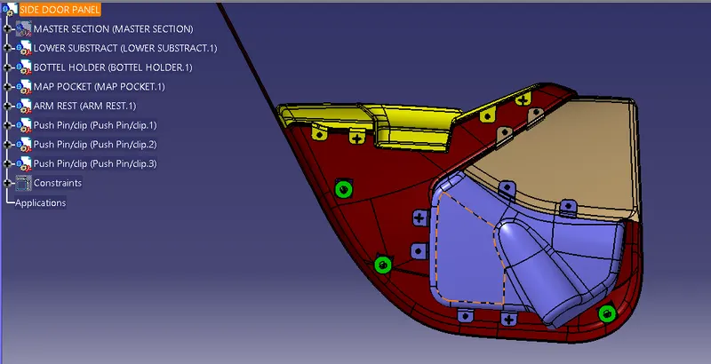
SIDE DOOR TRIM ASSEMBLY:
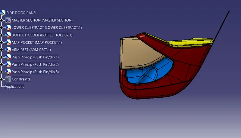
- CREATING B-SIDE FEATURES:
Engineering Features are created as per the master section.
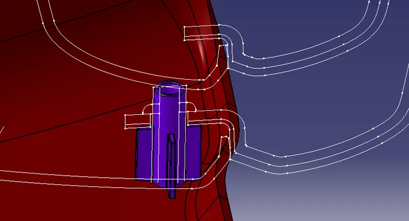
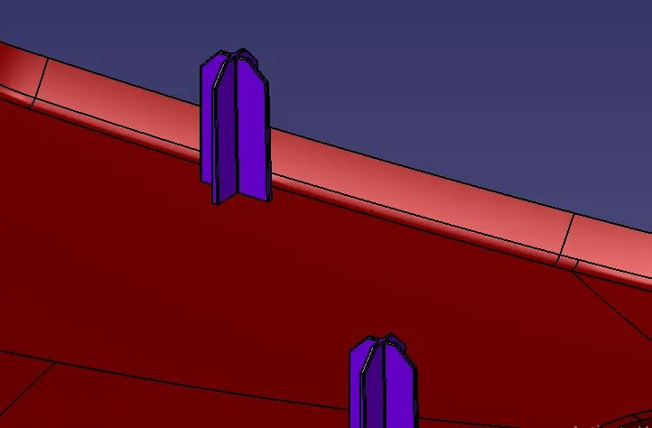
Heat Stake with Ribs
Heatsteak created as per the master section
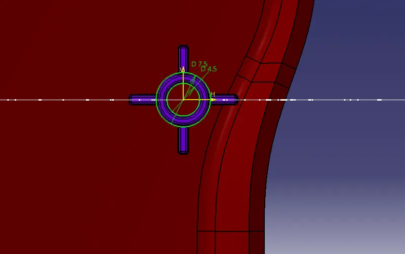
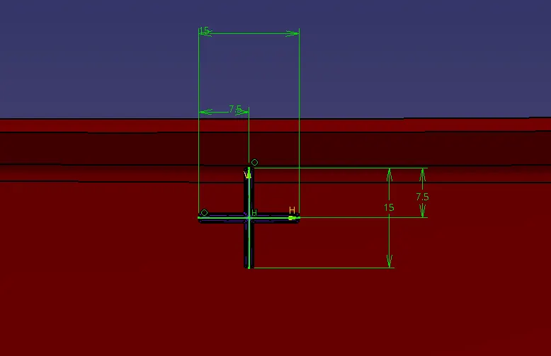
Ribs were added on both sides for strength to the heat stake. 15mm ribs were provided.
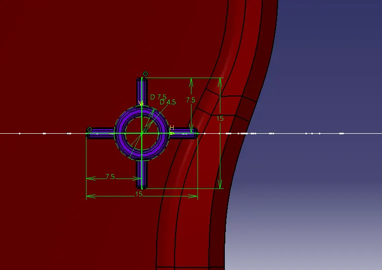
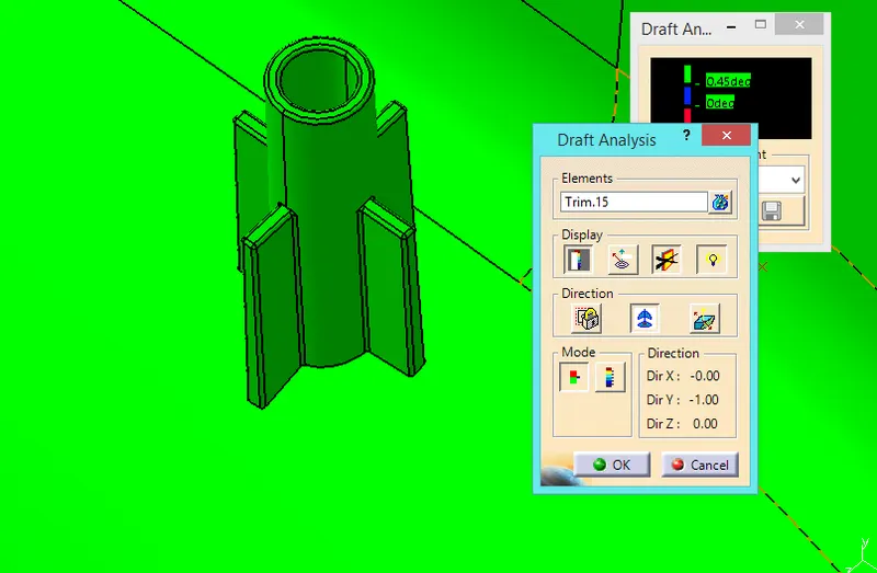
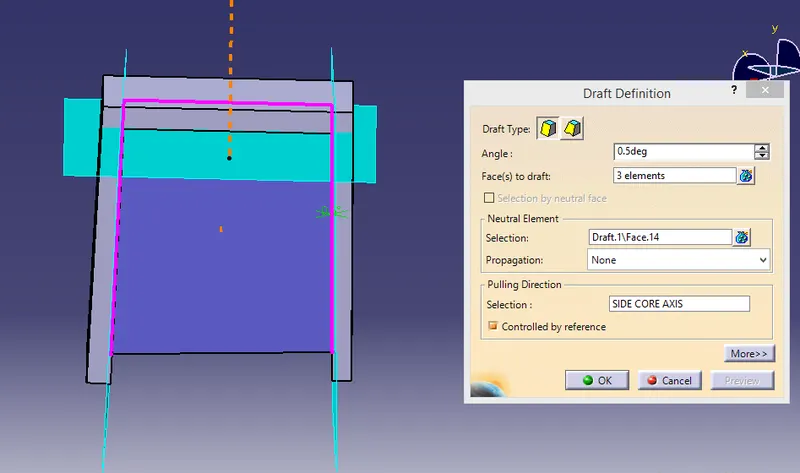
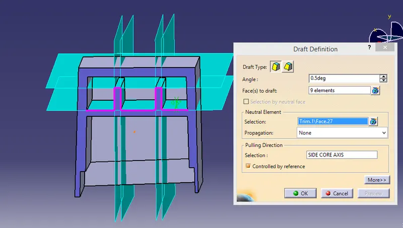
Provide the minimum Draft with main Tooling axis & Fillets.
Draft Anlysis
Transilate Heatsteaks & Uni trim with main body.The minimum gap between two heatsteak is 50 mm.
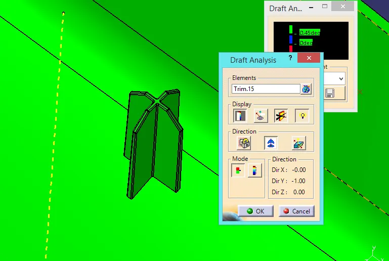
Locators
Locators also created in the Lower substract area to arest the degrees of freedom.Height of the locators should be more than that of the heat stakes.
Provide the minimum draft with main tooling axis,chamfer & Edge fillets
Transilate the Locators & Unitrim with main body
Draft Anlysis
Doghouse
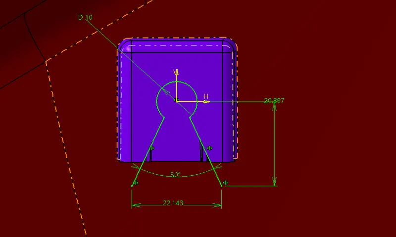
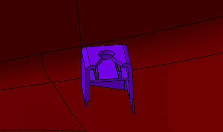
Dog house is an engineering feature used in plastic trim design. Dog houses are used as supporting feature which is created in Lower substract. Push pin assembled in Doghouse.
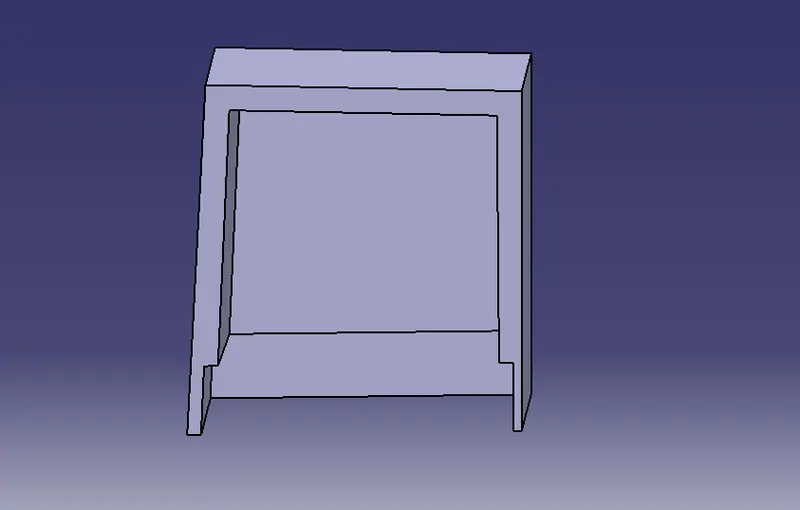
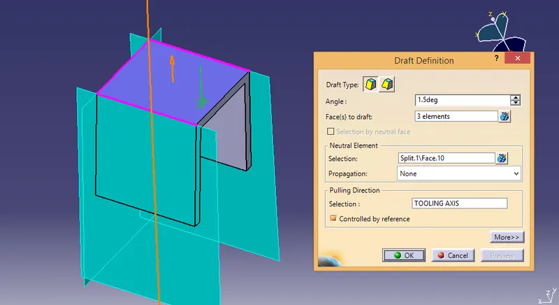
Supporting Rib is Created inside the Doghouse
Create the upper cut of Doghouse
Transilate the Doghouse as we Required and unitrim with main body.
Draft Analysis on Doghouse
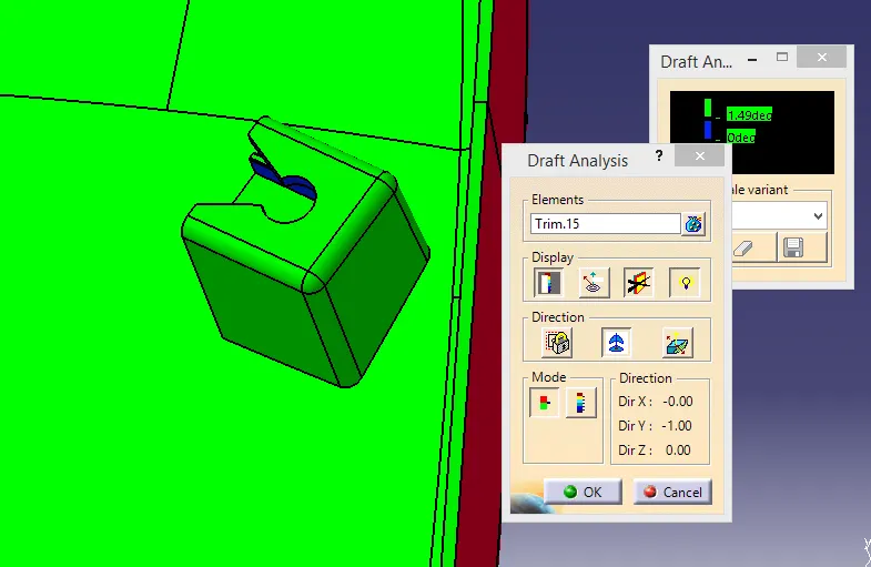
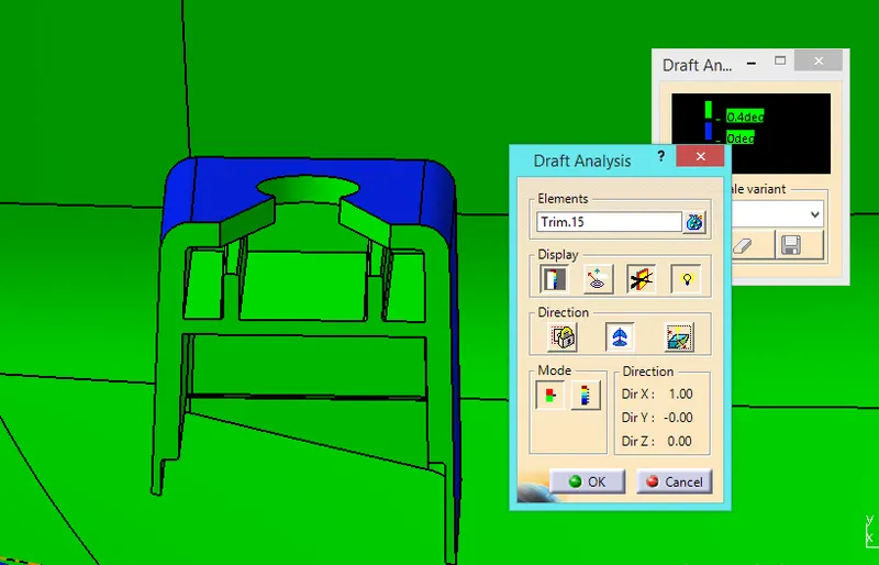
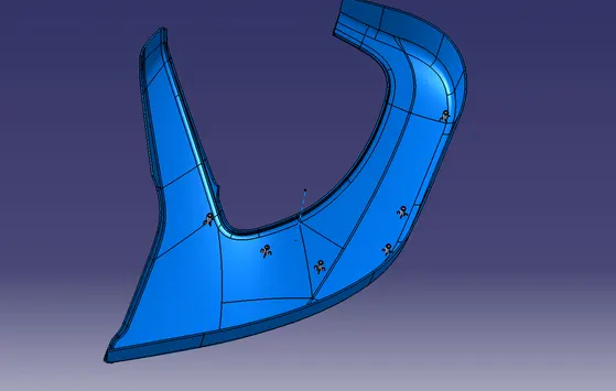
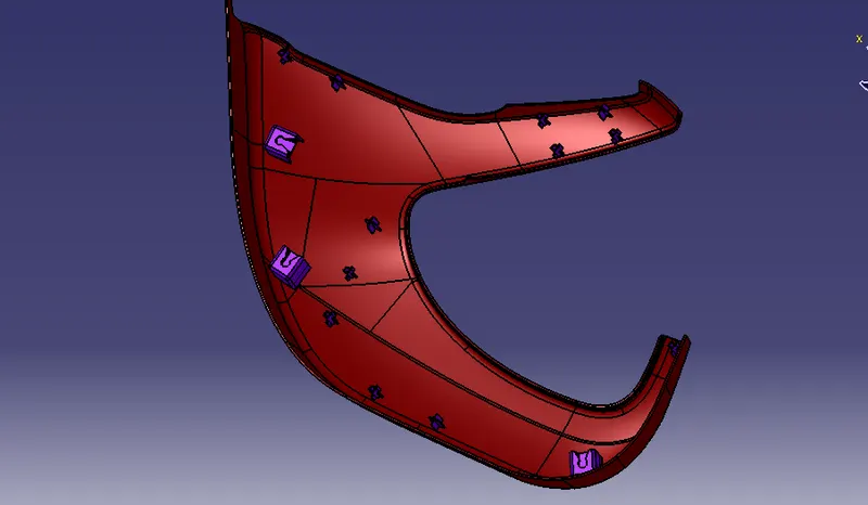
Final output of all B side features on the Lower substract.
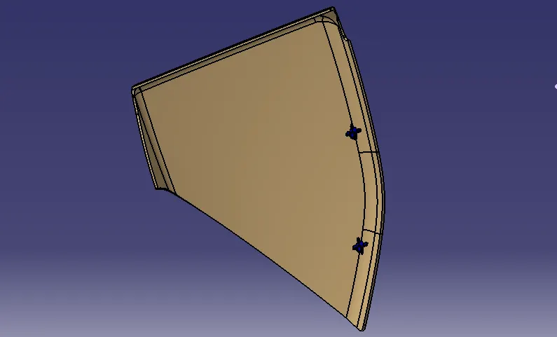
Final output of all B side features on the Map Pocket.
Flanges
Flanges are used to connect two part with each other,
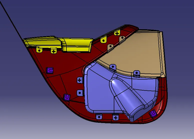
Now we need to make flanges for the Bottle holder,Map pocket and Arm Rest. The flanges surround the Heatsteaks and locators. The clearance b/w flange and Heatsteak should be 0.5mm and that b/w heatsteak and locator be 0.1mm.
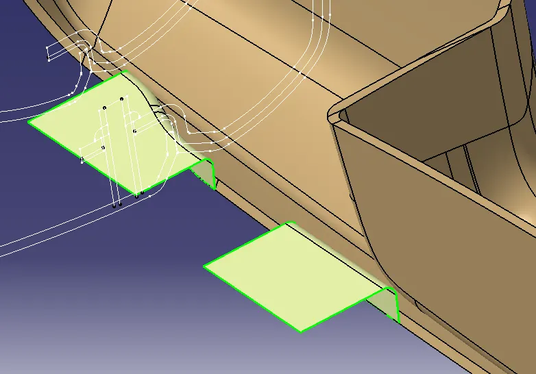
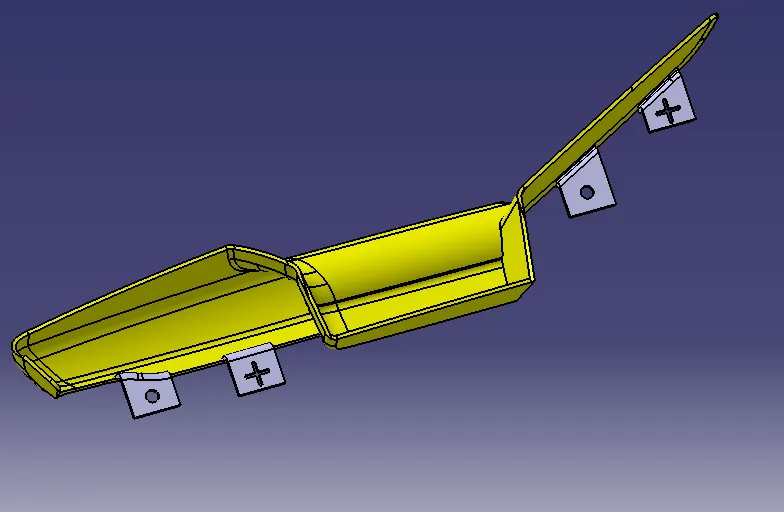
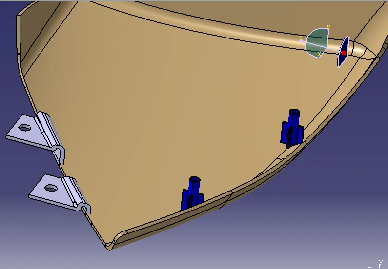
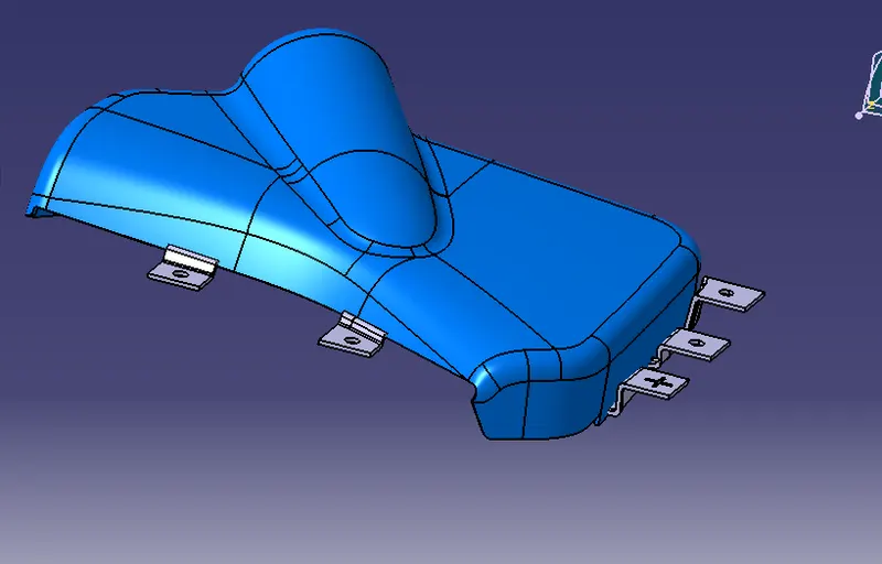
Give the Minimum draft & Edge fillet as per the master section.
All flanges have been provided now.
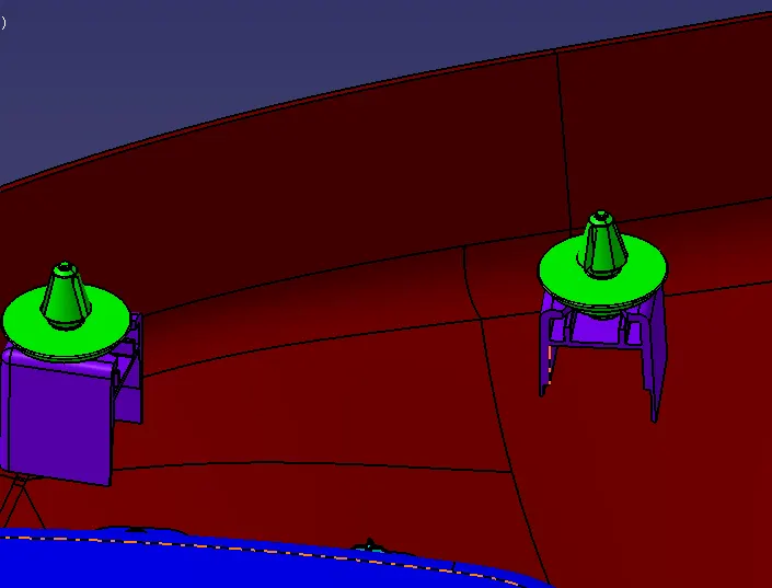
Push Pin Assembly
push pins have to be placed on top of all 3 doghouses.
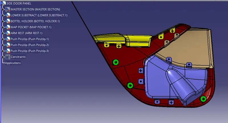
The push pins have been placed by assembly design using coincidence and surface constraints.
FINAL ASSEMBLY:
DRAFT ANALYSIS OF PLASTIC COMPONENTS:
Draft Analysis for Lower Substract
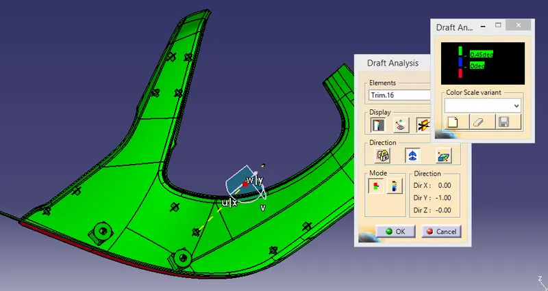
Draft Analysis for Arm Rest
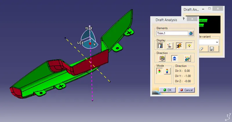
Draft Analysis for Map Pocket
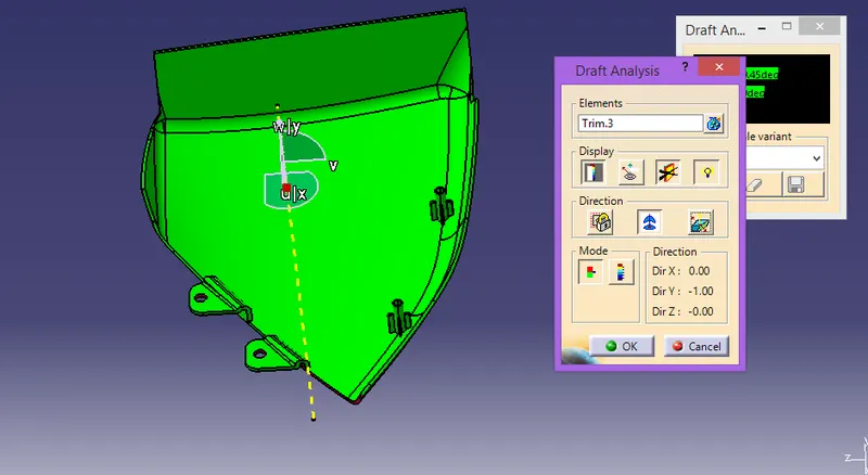
Draft Analysis for Bottle Holder
FINISHED PART
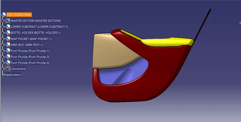
CONCLUSION: Hence the solid body of various parts of the door trim was made successfully with all necessary B-side features following all the design rules and guidelines.