DussehraFestive scholarship on Skill-Lync courses, this week onlyFestive scholarship is openOffer ends Wed, 21 Oct, 11:59 pm IST.
Dussehra 2026

Start your next chapter this Dussehra

Tell us where you want to work. A counsellor will match you to the right course and confirm the festive scholarship you qualify for.

  • Festive scholarship on course fees, confirmed on your call
  • Free 20-minute call to map the right course to your goal
  • Real industry projects and placement support with every course

Offer ends Wed, 21 Oct, 11:59 pm IST

3,905 engineers placed since 2019 · 1,277 hiring companies

By submitting you agree to our Terms and Privacy Policy.

You're on the list

Browse courses
Mechanical · PG program

Post Graduate Program inPre-Graduate Program in Engineering Design

A comprehensive program covering various aspects of engineering design exclusively for pre-graduate mechanical engineers

Duration
16 weeks
Content
56 hours
Courses
4
Projects
10
Mode
Online
Overview

What you'll
be able to do.

  • This program includes four different courses covering various aspects of engineering design.
  • The learners will have an understanding of the basic concepts employed while designing components.
  • They will get to know about the standards and trends followed in the industry for designing plastics and fixtures.
  • They will also gain exposure to standard practices followed in engineering drawing and GD&T.
  • This program also makes them gain hands-on experience in design tools like CATIA.

Why this program

  • After the completion of this program, the learners will be able to
    • Use CATIA for basic sketching operations to advanced surface designs
    • Design different BIW fixtures
    • Understand all the concepts, rules, symbology, conventions and principles related to the creation of engineering parts and assembly drawings
  • Job opportunities in top companies as design engineer
  • Job opportunities as an inspection engineer who can work on high-end measuring machines like CMM.
Tools you'll use
CATIA V5
Curriculum

4 courses,
39 modules.

  1. 01Automotive Plastic Design using CATIA V515 modules
    1. Design Overview In Automotive IndustryW01
      • In this session, you will learn
        • Product Life Cycle
        • Design Life Cycle
    2. Plastics in Automotive IndustryW02
      • In this session, you will learn
        • Types of plastics (Thermoset Plastics, Thermoplastic)
        • Engineering plastic Materials
        • Manufacturing Process
        • Injection Molding
    3. Introduction to CATIAW03
      • In this session, you will learn
        • Basic commands and operation
        • Save feature, pan feature, rotate feature, etc
    4. Sketcher workbenchW04
      • In this session, you will learn the following
        • Commands
        • Rules to follow
        • Working in exercise
    5. Part Design WorkbenchW05
      • In this session, you will learn
        • Pad and pocket
        • Working on exercise
    6. Advanced part designW06
      • In this session, you will learn
        • Boolean operations
        • How to work on a Boolean exercise
        • How to work on After Tool Go modification on Automotive components. (OEM Working procedures)
    7. 2D Drawing creationW07
      • In this session, you will learn to
        • Create a PCB Bracket using Boolean operations
    8. Basic Surface Design WorkbenchW08
      • In this session, you will learn the following
        • Commands (Types of Sweep)
        • Working on exercise
        • Draft analysis
        • How to work on a surface exercise
    9. Advanced Surface Design WorkbenchW09
      • In this session, you will learn the following
        • Commands
        • Creation of Closed body, Thickened body
        • A parting line and parting surface
    10. Creation of Door Switch Bezel and adding thickness to itW10
      • In this session, you will learn
        • How to create tooling direction and do the draft analysis to ensure the part can be taken out of the tool?
        • Adding the right thickness to the part and solving the issues.
        • Create the parting line for the bezel.
    11. Tooling FeasibilityW11
      • In this session, you will learn
        • What is a mounting feature?
        • How to create a locator and dog house?
        • Integrating the mounting features to the base part with Boolean operations
    12. Modeling ExerciseW12
      • In this session, you will learn
        • The Clip mounting feature is in Plastic design.
        • Design considerations for creating this feature
        • Tooling analysis for the clip feature
    13. Drafting WorkbenchW13
      • In this session, you will learn
        • Drafting workbench
        • Creation of detail drawing for the Components
        • Views creations (basic view & section views)
        • Application of GD&T in drawings
        • Template settings
    14. Mold Design ConsiderationsW14
      • In this session, you will learn
        • Creation of Paring line
        • Creation of Tooling axis
        • What is undercut and how to solve it
    15. Complex Mold Design ParametersW15
      • In this session, you will learn
        • Creation of simple mold for the Rear quarter trim Cupholder
        • What are core and cavity
        • Stripper, ejection, and system
        • Draft analysis
      • Designing a mold gives a good working understanding of the molding aspects of a component
  2. 02Automotive BIW Fixture Design using CATIA V510 modules
    1. Introduction to BIW-FixtureW01
      • In this session, you will learn
        • Definition of BIW, Jigs, & Fixture
        • BIW-Nomenclature
        • Types of Fixtures & their applications
        • BIW stations & their uses
        • Basic terminologies
    2. BIW-Fixture BasicsW02
      • In this session, you will learn
        • Project activities
        • Different welding processes
        • 3-2-1 Principle
        • Body planes
    3. Pre-Design ProcessesW03
      • In this session, you will learn
        • Design methodology
        • Structuring a design tree
        • Different types of fixture units
    4. Units Design-1W04
      • In this session, you will learn
        • Different types of Pin Unit Design
        • Different types of Clamp Unit Design
        • Different types of Rest Unit Design
    5. Units Design-2W05
      • In this session, you will learn
        • Dump Unit Design
        • Slide Unit Design
        • Base Unit Design
    6. Finishing of the designW06
      • In this session, you will learn
        • 3D-finish
        • Rough locators
        • Pneumatic routing
        • Valve banks & selection
        • Gun study
        • Sensors & selection
    7. 2D-Detailing Basics W07
      • In this session, you will learn
        • Drawing templates
        • Angles of projection
        • Basic GD&T used in fixturing
        • Scaling & views
        • Various detailing patterns
    8. 2D-Detailing W08
      • In this session, you will learn
        • Key Sheet detailing
        • Unit detailing
        • Child parts detailing
    9. 2D-Detailing - Child Part & BOMW09
      • In this session, you will learn
        • Child parts detailing
        • Material selection
        • BOM Preparation
    10. Documentations, Sequence Sheet & Process SheetsW10
      • In this session, you will learn
        • Creation of BOM sheets
        • Creation of BOP sheets
  3. 03Engineering Drawing7 modules
    1. Week 01 Engineering Drawings BasicsW01
      • This week, we will learn about
        • Workbench centre
        • First and third-angle projection
        • Auxiliary Views
        • Partial Views
        • Cut Section Views
        • Cutting Plane
        • Hatching or Section Lines
        • Section View
        • Broken out Sections
        • Offset Section
        • Revolved Section
        • Cross-Hatching Section Views
        • Sectioning Conventions
        • Section through Ribs
        • Sections through Bolt and Stud in Assembly
        • Sections through Drilled and Tappered Blind Holes
        • Feature Rotation
        • Convention for Long Parts
    2. Week 02 DimensionsW02
      • This week, we will learn about
        • Dimension
        • Extension Lines
        • Drawing Notes
        • Fundamental Drawing Requirements
        • Implied Geometric Form
        • Oblique Extension Lines
        • Grouping Dimension Lines
        • Staggered Numerals
        • Limited Area or Length Indication
        • Leader Lines
        • Minimizing Leader Lines
        • Dimensioning Long Parts
        • Reference Dimensions
        • Dimensioning Features
        • Diameter Dimensions
        • Dimension of Circular Arcs
        • X Symbol in times and by
        • True Dimension
        • Dimensioning Slotted Hole
        • ASME Hole Depth Symbol, Countersink Symbol, Spot-facing, Chamfers
        • Dimensioning Non-Circular Line and Knurling,
        • Rectangular Coordinate Dimensioning
    3. Week 03 TolerancingW03
      • This week, we will learn about
        • Introduction to Tolerancing
        • Unilateral and Bilateral Tolerances
        • Limit Dimensioning
        • Comparison of Millimetre and Inch Unilateral Tolerances
        • Comparison of Millimetre and Inch Bilateral Tolerances
        • Comparison of Millimetre and Inch Limit Tolerances
        • Chain Dimensioning
        • Baseline Dimensioning
        • Direct Dimensioning
        • Tolerancing Angle
        • Form Dimensioning
        • Specifications of Flat Taper
        • Tolerancing angle
    4. Week 04 Limits and FitsW04
      • This week, we will learn about
        • Terms used in Fits
        • Material Conditions
        • Envelope Condition, Go, and No Go Guage
        • Fits between Parts
        • Fits between Fits
        • Clearance, Transition, and Interference Fits
        • Types of Fits
        • Deviations
        • Machine Process and Tolerance Grades
        • Tolerance Grades
        • ISO Tolerance Grades
    5. Week 05 Fundamental Dimensioning and Tolerancing RulesW05
      • This week, we will learn about
        • Fundamentals of Dimensioning and Tolerancing Tools
        • Drawings Explanation of Different Parts of a Lathe
        • Rules for Fundamental Dimensioning and Tolerancing
        • Drawing Checklist
    6. Week 06 Surface TopographyW06
      • Surface Topography
        • Roughness
        • Form Error
        • Waviness
      • Symbols for Representation
      • Methods of Placing Surface Roughness Symbols
      • Surface Roughness Measurement
        • Skid
        • Skidless
      • Selection of Cut-Off Length
      • Drawing Indication of Surface Lay
      • Welded Joints
      • Types of Welds
      • Welding Symbols
      • Weld Supplementary Symbols
      • Finish and Contour Symbols
      • Welding Symbol
    7. Week 07 Layout of a Rectangular Sheet Metal BoxW07
      • Sheet Metal Box
      • Sheet Metal Materials
      • Dimensioning Sheet Metal Part
      • Sheet Metal Design Guidelines
        • Plastic Parts
        • Corner Radii
        • Uniform Wall Thickness
        • Sink in Plastic Molding
        • Ribs and Gussets
        • Draft Angle
        • Bosses in Plastic Parts
        • Dimensioning Holes
        • Surface Finish of Plastic Parts
  4. 04Geometric Dimensioning and Tolerancing7 modules
    1. Introduction to GD&TW01
      In this module, you will study GD&T and its uses. After your first class, you will be able to understand the basics such as:
      • Difference between traditional dimensioning and GD&T
      • Benefits of GD&T
      • How to read a feature control frame
      • Technical standards- ASME Y14.5M-2009
      • Different symbols used in GD&T, cover, and feature of size
    2. Rules, Symbols, and Form TolerancesW02

      In this module, you will learn about the governing rules of GD&T. After this class, you will have an understanding of:

      • Rule No. 1 (i.e. Taylor principle a.k.a envelope principle)
      • Rule No. 2 (Regardless of feature size)
      • 14 symbols used in GD&T
      • Flatness, straightness, cylindricity, and circularity tolerances
      • MMC, LMC, and RFS conditions
      • Various examples for form tolerances
    3. Datums, Modifiers, Virtual ConditionW03

      In this segment, you will study the following topics:

      • What are datums and how to apply datums to parts
      • Datum reference features
      • Datum feature modifiers
      • How to calculate virtual condition
      • Conjugated datums
    4. Orientation Tolerance and Profile ToleranceW04

      At the beginning of this section, you will have built a good base for learning complex tolerances. In this section you will learn:

      • Profile of a surface and profile of a line
      • Perpendicularity tolerance, parallelism tolerance, and angularity tolerance
      • Composite profile tolerance
      • Various examples for orientation and profile tolerances
    5. Position ToleranceW05

      Position tolerance is the most widely used tolerance in GD&T.

      In this section we will go through:

      • Understanding true position
      • Projected tolerance
      • Composite tolerances
      • Tolerance zones- cylindrical, rectangular, spherical
      • Examples of position tolerance
    6. Co-axiality, Symmetricity, Run-outsW06

      By now, you will have enough knowledge to read an entire GD&T drawing and understand it. In this section, you will learn about some tolerances that are not widely used in the industry but are mentioned in the ASME standard

      You will learn:

      • Coaxiality
      • Symmetricity
      • Circular and Total Run Outs
      • Examples
    7. Understanding GD&T DrawingW07

      In this part, you will study complex GD&T drawings and understand every individual tolerance and the message the tolerance conveys.

Industry projects

10 projects
you'll ship.

Our projects are designed by experts in the industry to reflect industry standards. By working through our projects, Learners will gain a practical understanding of what they will take on at a larger-scale in the industry. In total, there are 10 Projects that are available in this program.

Design of Coin Holder
Automotive Plastic Design using CATIA V5

Design of Coin Holder

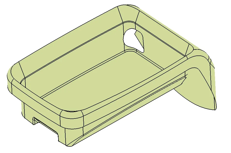
In this project, you will design a coin holder plastic trim part from the given Class-A surface. Check if the product is manufacturable.
Design of Heat Staking
Automotive Plastic Design using CATIA V5

Design of Heat Staking

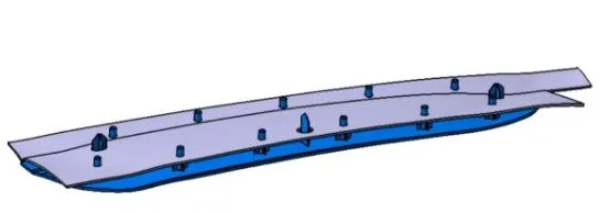
In this project, the students will design heat stakes for joining the plastic door. The students will apply the 3-2-1 principle for designing the plastic applique.
Design of Switch Bezel
Automotive Plastic Design using CATIA V5

Design of Switch Bezel

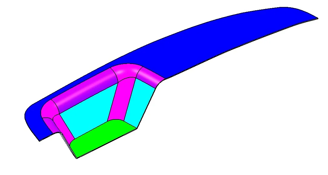
This project is about the development of a car side door switch bezel. You will be creating the CAD model of the switch bezel from the given inputs.
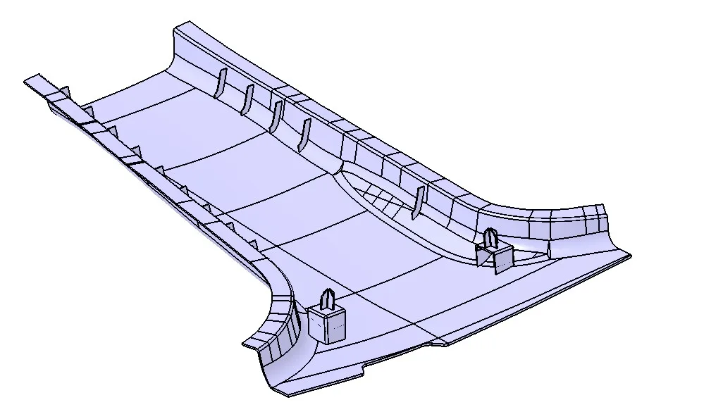
Design of B-pillar Cover
Automotive Plastic Design using CATIA V5

Design of B-pillar Cover

The project deals with the design of a B-pillar cover. The students will create a Plastic B pillar trim from the given class-A surface.
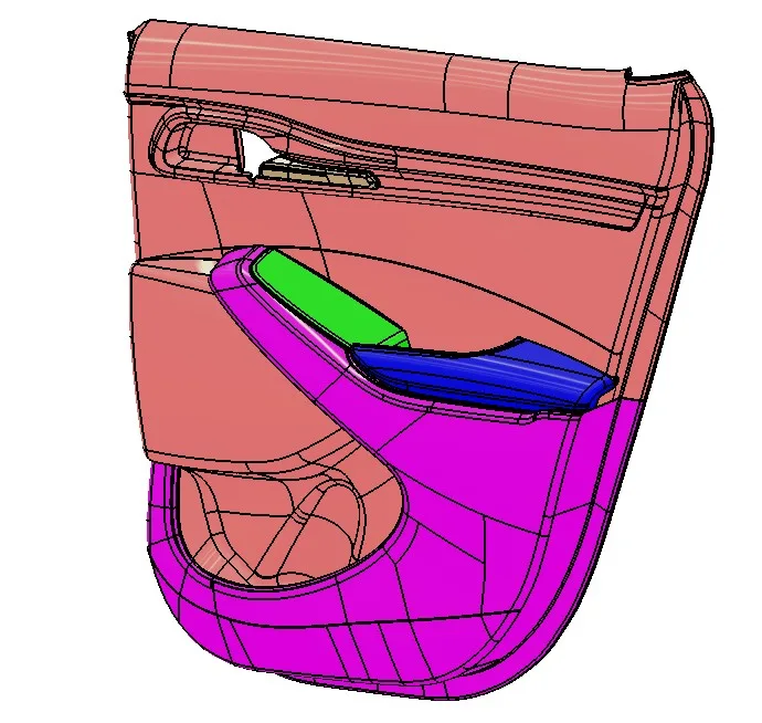
Design of Side door Panel
Automotive Plastic Design using CATIA V5

Design of Side door Panel

In this project, you will create a complete side door panel. You will design all the sub-assemblies like the armrest, map pocket, and the lower substrate.
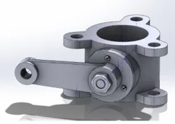
Butterfly Valve Design
Geometric Dimensioning and Tolerancing

Butterfly Valve Design

In this project, you will learn about GD&T and its application for Butterfly valve assembly.
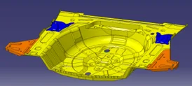
Designing a Robot Welding Fixture
Automotive BIW Fixture Design using CATIA V5

Designing a Robot Welding Fixture

In this project, the students will be working on the design and development of a robotic welding fixture. Here, the students will create the assembly and child-part drawings for th…
Designing a Manual Welding Fixture
Automotive BIW Fixture Design using CATIA V5

Designing a Manual Welding Fixture

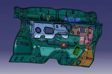
In this project, the students will be working on the design and development of a manual welding fixture. The students will also create the assembly and child-part drawings for the …

09
Engineering Drawing

Assembly Drawing

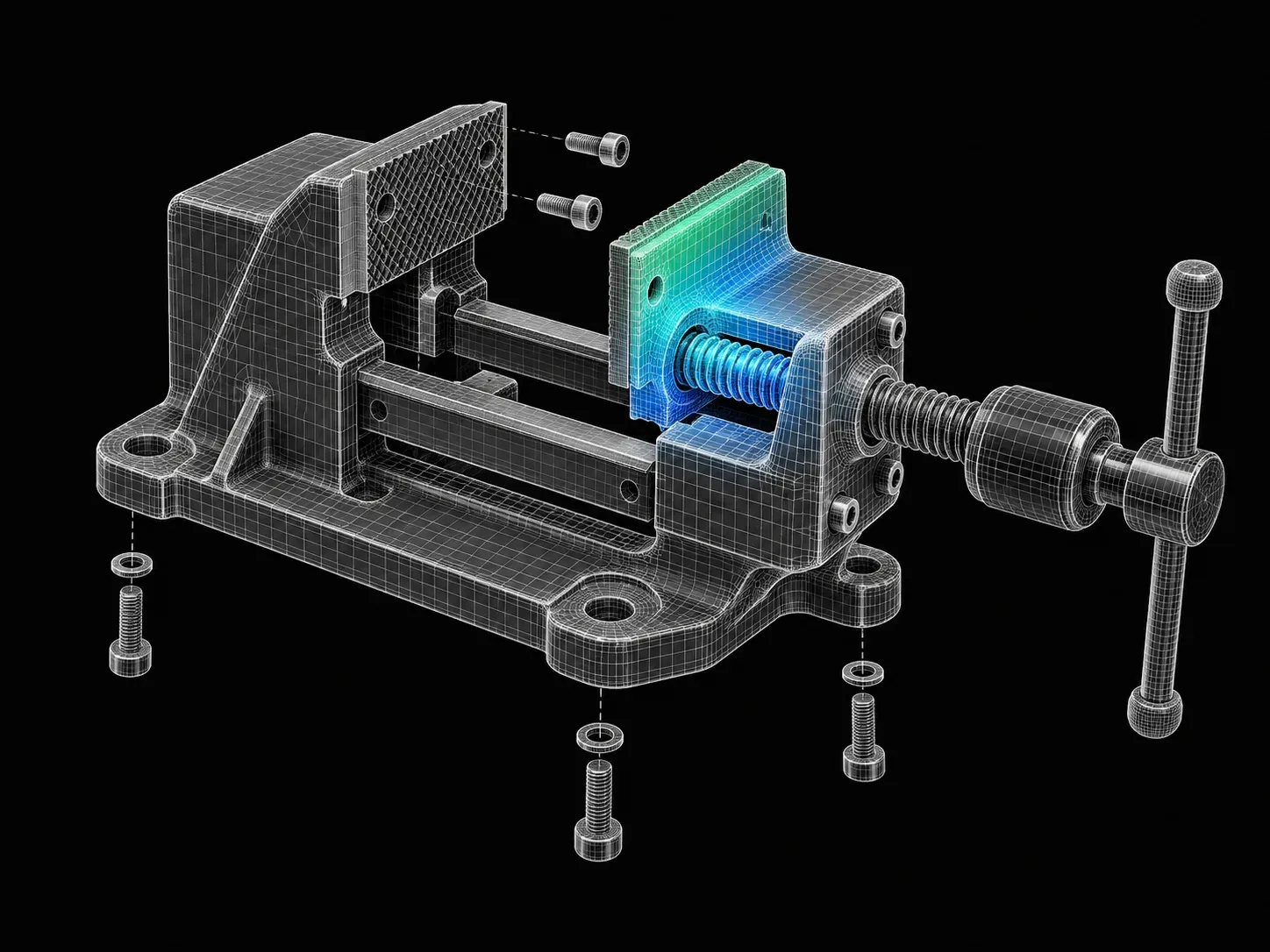
In this project, you will be provided with the assembly drawing and an STP file for the assembly of the parallel vice. You will be tasked to create the child part drawings for all …

10
Engineering Drawing

Grinding Machine Table

This project will include a 2D drawing of a Grinding Machine Table with the tolerances applied to it.

Fee

One fee.
Everything included.

Become job ready with our comprehensive industry focused curriculum for freshers & early career professionals

Premium
₹1,50,000
Inclusive of all chargesEMI from ₹7,841/month
  • Career Service Assurance
  • Personalized Career Services Mentorship
  • 1 Year Access
  • Personalized Page
  • Live Individual & Group Sessions
  • Personalized & Hands-On
  • Job-Oriented Industry Relevant Curriculum
Check eligibility →
Next step

Not sure it's
the right fit?

A counsellor will walk you through the syllabus, projects and fee options — and tell you honestly if another course suits you better.

Get the syllabus + a call back

We'll email the full syllabus and call within one working day.

By submitting you agree to our Terms and Privacy Policy.

Call usEnquire

Talk to a career counsellor

Free 20-minute call. We'll map the right course to where you want to work.

By submitting you agree to our Terms and Privacy Policy.