Week 10 - Challenge 3 - Door Trim Lower with Engineering Features
AIM:To create a solid body of 'Door Trim Lower' with the help of the closed surface method by using the 'Generative shape design' workbench. Performing the 'Draft Analysis' on the solid part body of the Door trim.Create the Heat Stakes and the locators considering the design rules.
OBJECTIVE:
- To create a tooling direction.
- To perform draft analysis for given Class A-Surface .
- To design the B-Surface and C-Surface using the given Class-A surface.
- Take the Thickness of the component to be 2.5 mm.
Create the Heat Stakes and the locators considering all the design rules.
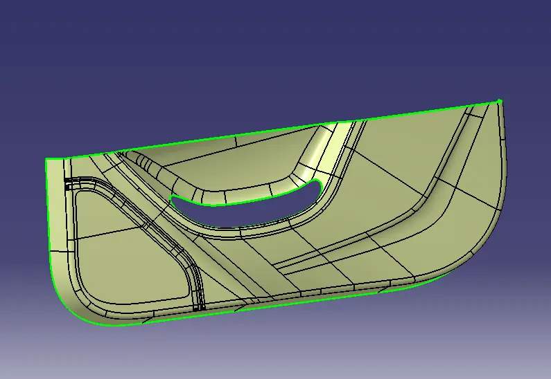
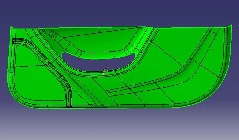
- CLASS A SURFACE
Given Class A Surface
TOOLING AXIS:
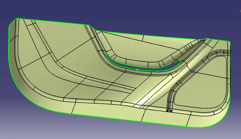
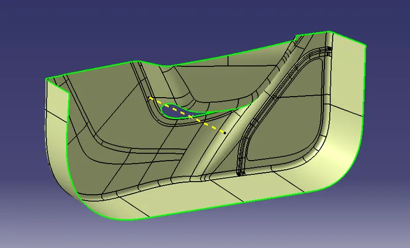
observe the given class-A surface and find the proper surface to create Tooling axis,
- Create a Point on curve.
- Draw a Point To diraction line through that point along Y component.
DRAFT ANALYSIS:
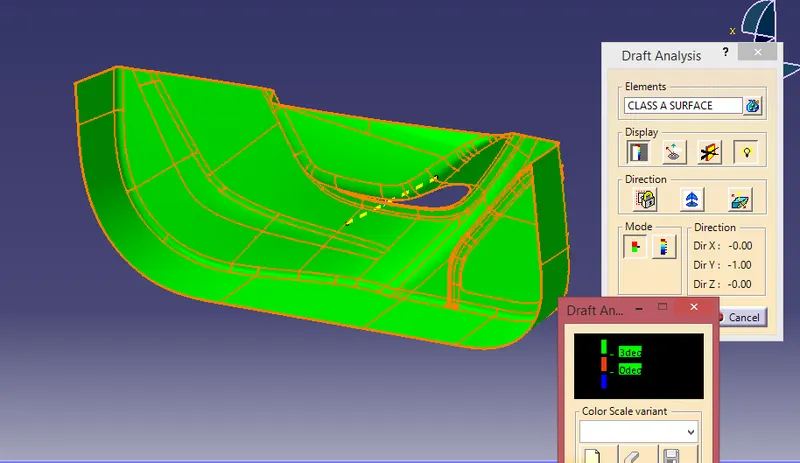
Draft analysis for the given CLASS-A surface,
Draft analysis is done after determining the tooling axis, draft analysis is used to check whether the minimum draft (3 degrees) is maintained or not.
- Open the featured draft analysis tool.
- Drag and align the compass on the Tooling axis.
Lock the draft direction and perform draft analysis by clicking on the component
- CLASS B SURFACE
Class B Surface is created With the help Class A Surface
- Offset the class-A surface to 2.5mm inward direction.
- Remove patches and discontinuity of the offset surfaces using the features like extract, multi-extract,Un trim, extrapolate.
- Provide proper Fillets and Join.
To ensure there is no gap in Class-B surfaces ,check the boundary command to find out the boundary
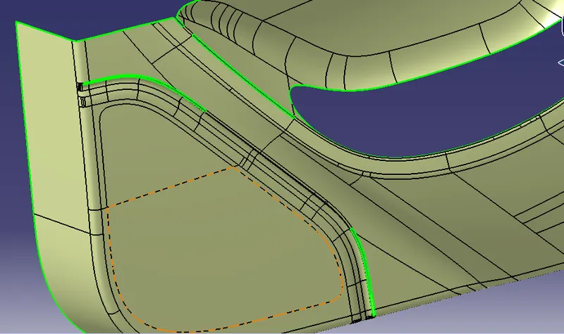
Class B Surface
- CLASS C SURFACE
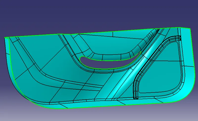
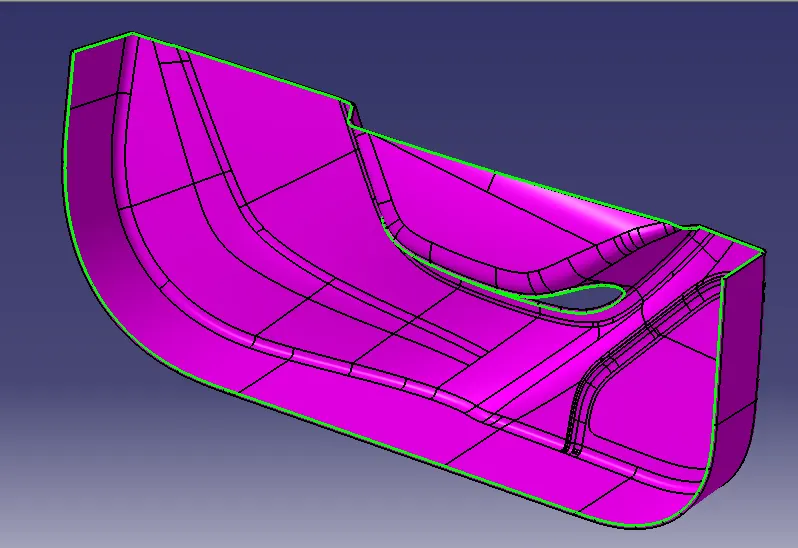
Class C is created with help of A-Surface,The Surface that joins class-A and class-B surfaces.
- Create the Boundary
- Sweep 4mm at 90 degree,With reference surface.
- Extrapulate edges & Trim.
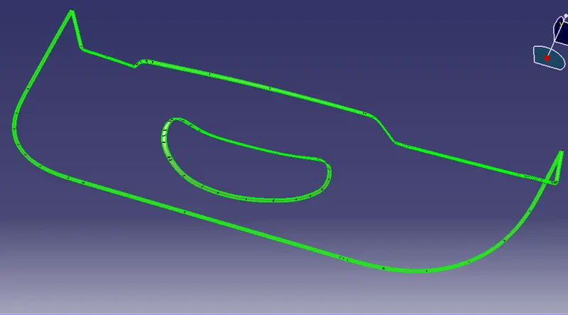
JOIN CLASS C WITH CLASS A
A+C Surface
- FINAL TRIM
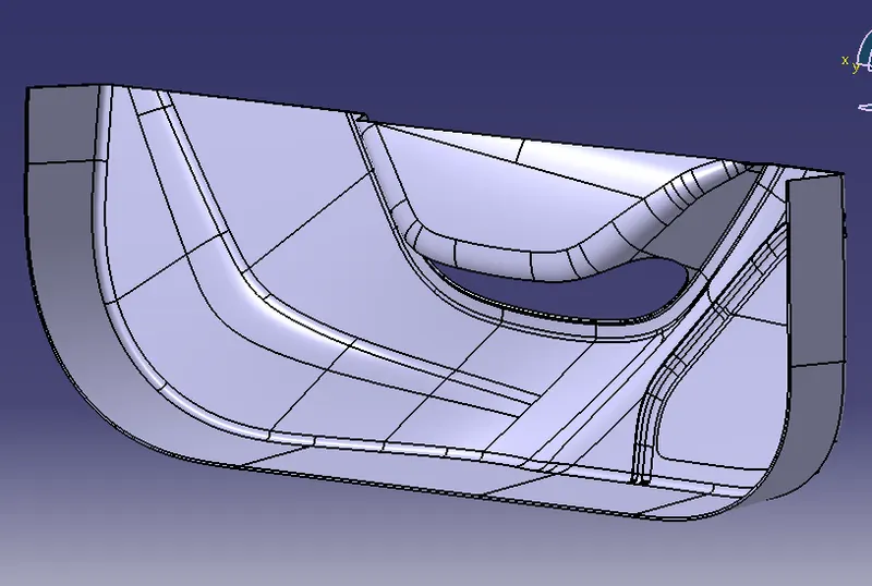
Trim the Joined surface with CLASS-B surface to achieve the final Out put.
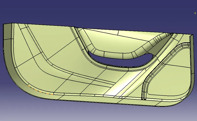
In part design work bench and using the close surface command create the part as solid part body.
CREATION OF LOCATORS:
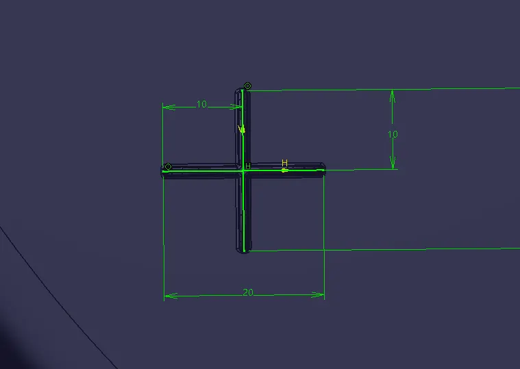
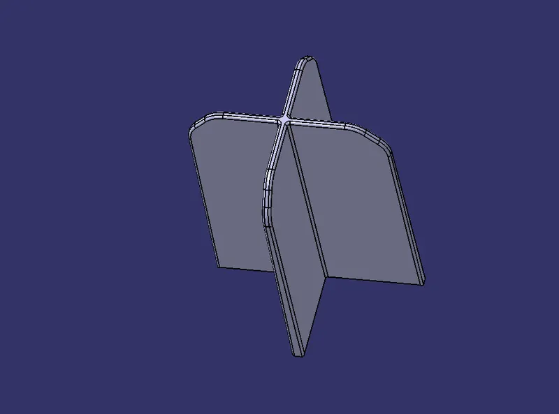
- 4-WAY LOCATOR
- To create a sketch on the body.
- Pad it 20mm in height and thicken it to 1.3mm.
- drafted it with 0.5deg in the direction of the tooling axis.
- Provide 3mm of chamfer with 45deg of inclination and fillet of 0.3mm radius.
- 2-WAY LOCATOR
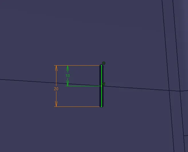
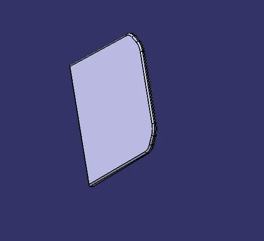
- HEAT STAKES
- To draw a sketch on the surface.
- Pad it to 15mm.
- To gave a draft angle of 0.5deg on both sides (inside and outside).
- Give fillet with a 0.25mm radius.
After creating the RIB for supporting purposes.
- Draw a sketch and padded it to 6mm in height and 1mm in thickness.
- Drafted 0.5deg in the tooling asix direction.
- filleted it with a 0.25mm radius.
Finally,Union trim the ribs with a heat stake to remove the ribs which are present inside the heat stakes.
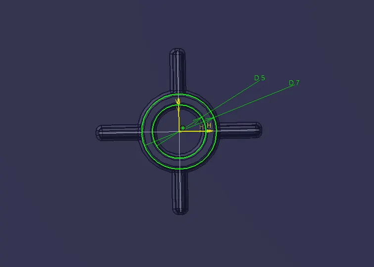
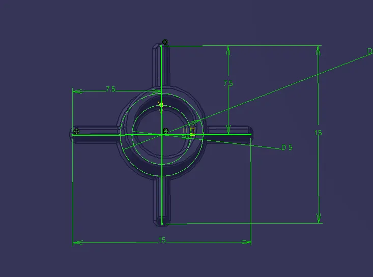
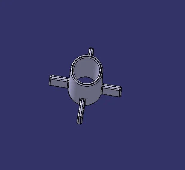
Translated the heat stakes by copy-pasting them in the part body according to the requirement.
Final part body with 4-way and 2-way locators including all the Heat stakes with supporting ribs.
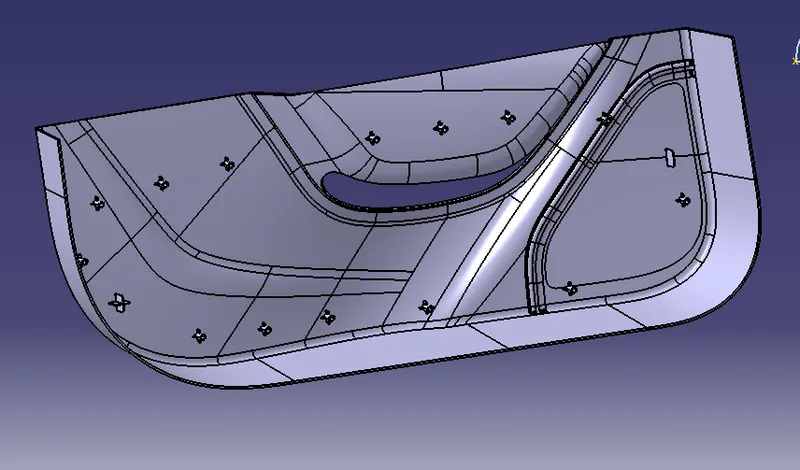
DRAFT ANALYSIS FOR PART BODY:
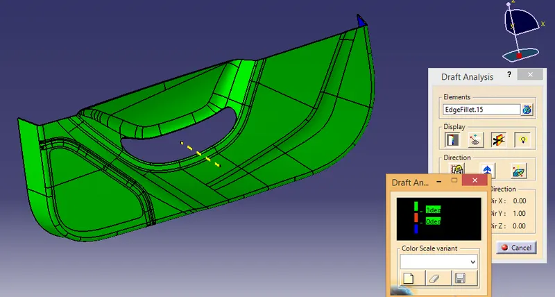
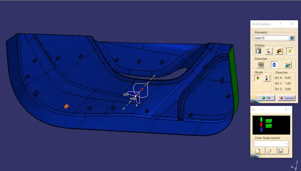
Some faces are not cleared properly, this is due to the curvature and inclinations on the class A surface
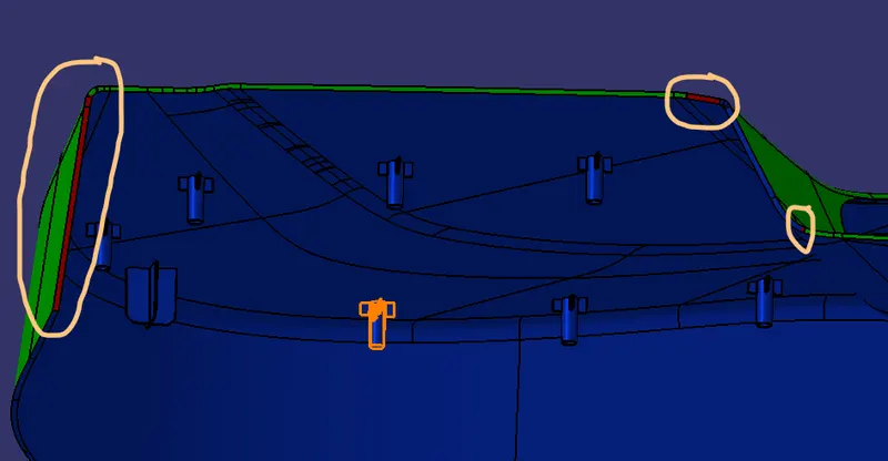
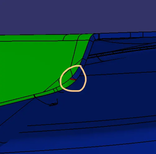
- Draft analysis for Heat stakes and Locators:
The draft angle for heat stakes and locators is 0.5deg.So 0.48 is give to check Draft.
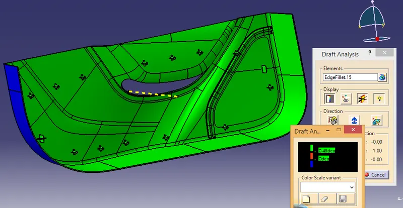
RESULT:Thus the solid body of 'Door Trim Lower' is created and the Heat Stakes and the locators are created considering the design rules.