Week 14 challenge
AIM:To Assemble and apply GD&T to the butterfly valve assembly drawing.
OBJECTIVE:
- To design of Butterfly Valve in appropriate dimension with the application of GD&T
- To assemble all the parts of the butterfly valve by assigning suitable constraints.
- To understand the concept of geometric tolerance and dimensioning.
INTRODUCTION:
BUTTERFLY VALVE
A butterfly valve is a valve that isolates or regulates the flow of a fluid. The closing mechanism is a disk that rotates. A butterfly valve is from a family of valves called quarter-turn valves. In operation, the valve is fully open or closed when the disc is rotated a quarter turn. The "butterfly" is a metal disc mounted on a rod. When the valve is closed, the disc is turned so that it completely blocks off the passageway. When the valve is fully open, the disc is rotated a quarter turn so that it allows an almost unrestricted passage of the fluid. The valve may also be opened incrementally to throttle flow.
Parts of Butterfly Valves
- Butterfly valve body
- Shaft
- Disc Plate
- Lever
- Retainer
- Nut
- Screw
DESIGN & METHODOLOGY:
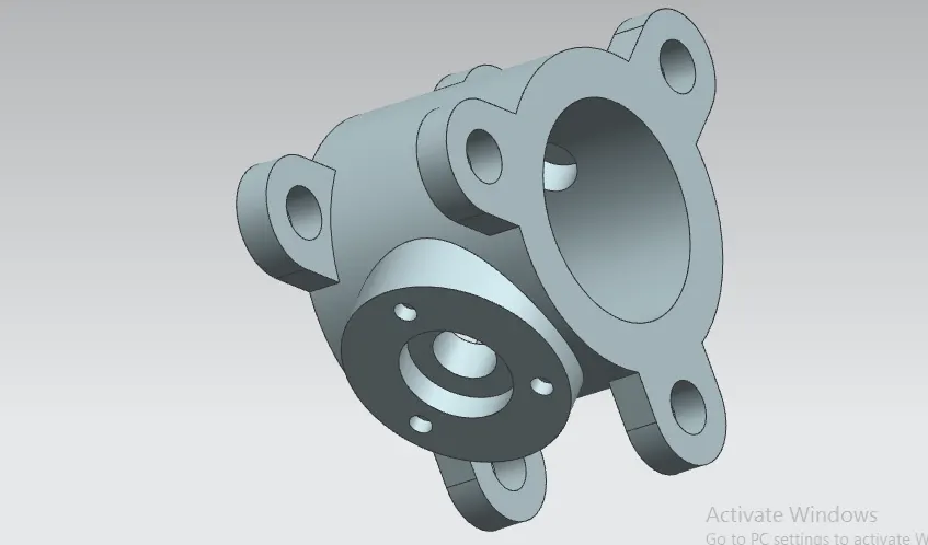
- Butterfly valve body
The body is the housing for the internal components and it is the main part of the butterfly valve. The body connects to two pipes on its two sides and it regulates to flow.
The model is created in Nx.
Features used to create the Butterfly Valve :
- Sketch
- Extrude
- datum plane and coordinate
- counterhole Bore
- unite
- Shaft
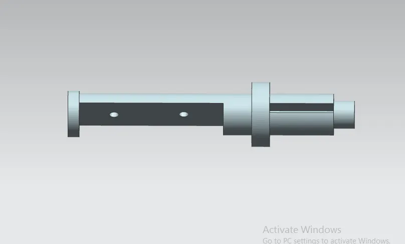
It inserts into the body of the valve and sits perpendicular to the direction of flow. It holds the disc inside the body and is clamped with the lever outside the body. It is created using simple features like revolve and extrudes features in the NX modeling environment.
Features used to create Shaft :
- Sketch
- Revolve
- Datum plane
- Extrude
- chamfer
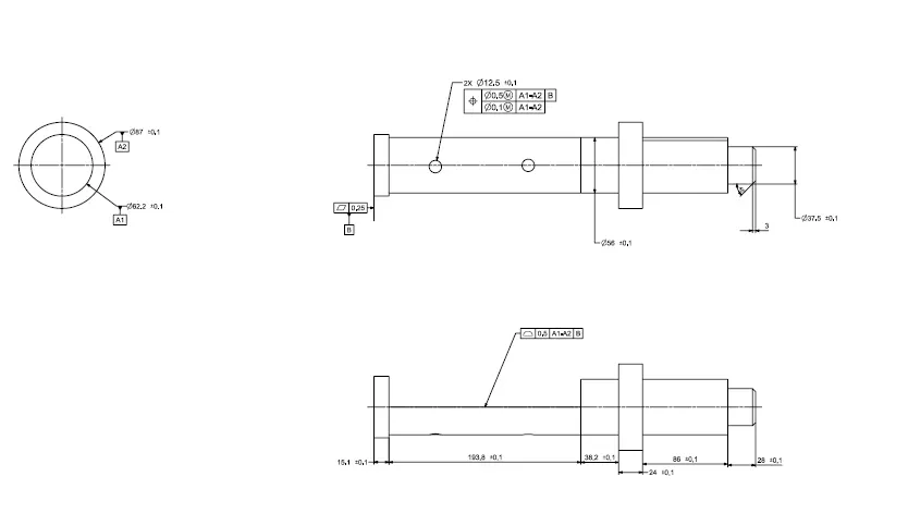
Drafting Methodology :
GD&T is applied using the features of NX.
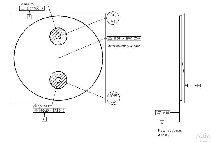
- Disc Plate
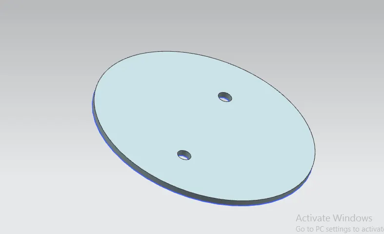
This disc plate is the main component of the butterfly valve which regulates the flow in the valve. The orientation of this disc determines the flow rate of the fluid. It is not perfectly circular, rather it is elliptical in profile. The holes in it help to position it properly on the shaft created earlier.
Features used to create Shaft :
- Sketch
- Extrude
Drafting Methodology :
GD&T is applied using the features of NX.
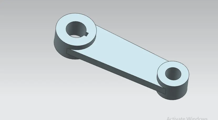
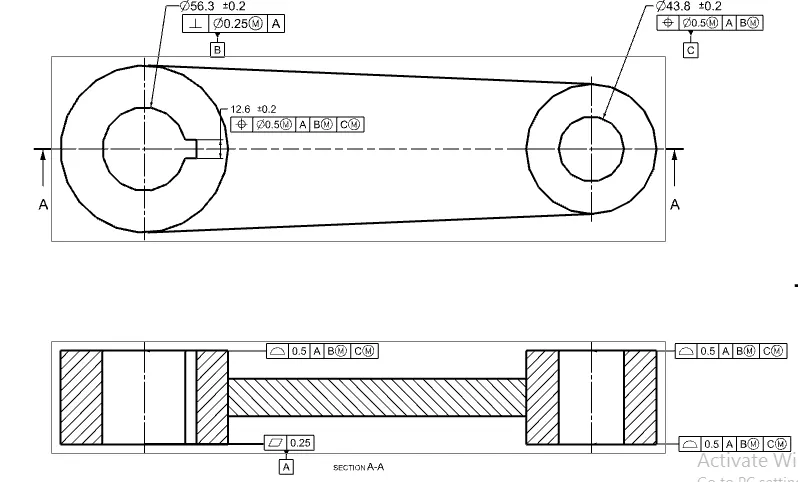
- Lever
A lever is a handle that is used to rotate to regulate the flow. It is attached to the shaft with the help of a key to fixing it in position concerning it. So when it is rotated, the shaft rotates which in turn rotates the disc and regulates the flow inside the pipe.
Features used to create Lever :
- Sketch
- Extrude
Drafting Methodology :
GD&T is applied using the features of NX.
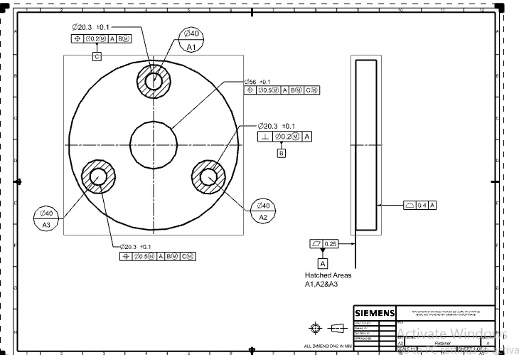
- Retainer
This part helps to retain or to fix the shaft with the body of the butterfly valve. It prevents the shaft from coming out of the body and keeps it in position for the proper functioning of the disc inside the body.
Features used to create Retainer :
- Sketch
- Extrude
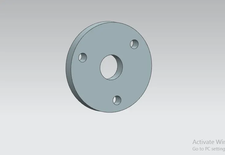
Drafting Methodology :
GD&T is applied using the features of NX.
- Nut
This part that helps to fix the lever in position with the stem. It allows to keep it in position or to disassemble whenever required.
Features used to create Nut:
- Sketch
- Extrude
- Revolve
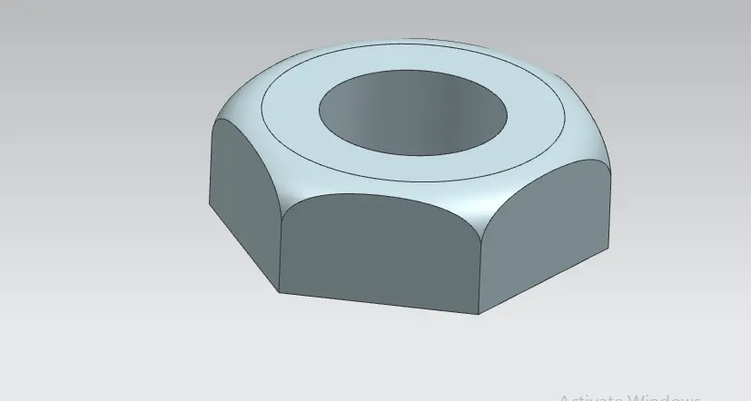
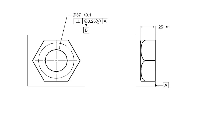
Drafting Methodology :
GD&T is applied using the features of NX.
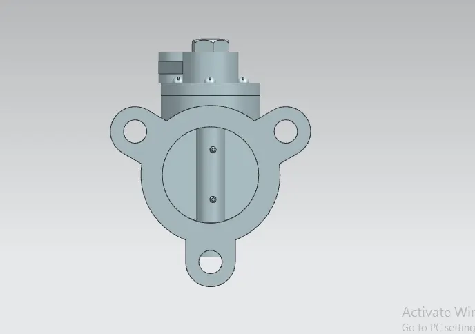
ASSEMBLY OF BUTTERFLY VALVE:
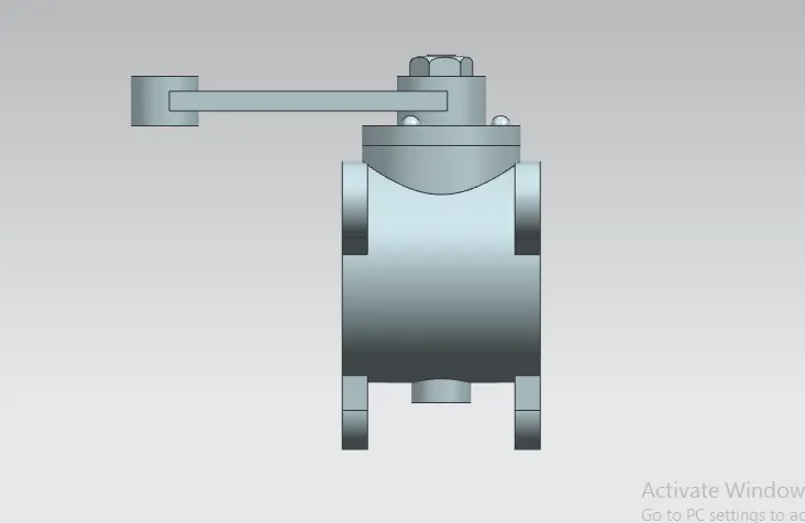
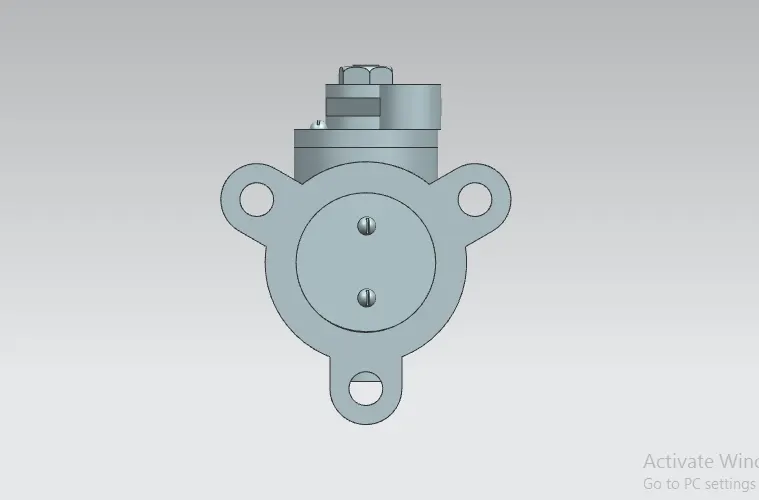
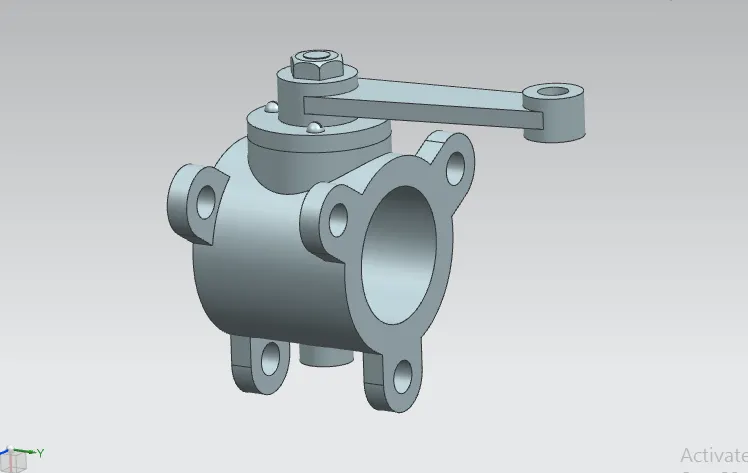
After the design, all the models should assemble with appropriate constraints.
First, the shaft and disc are joined together with the screws in place to create a sub-assembly which is then joined to the body in position. The retainer plate is then mated with the body and screws are used to fix them. After that, the lever is mated to the shaft in a position that is then fixed after the nut is mated with the shaft.
Features used to Assembly
- Infer Axis/center
- Touch Align
- Concentric
- Move Component
Drafting Methodology
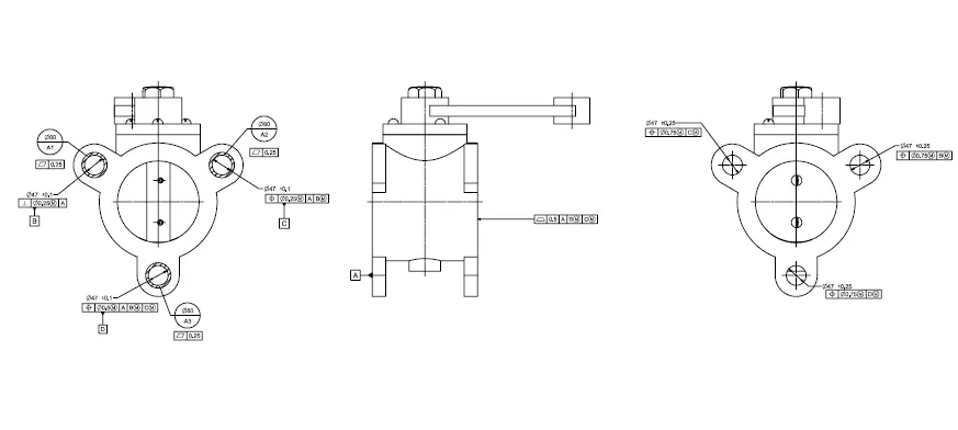
- Datum target area A1,A2 and A3 is given to the ears of the butterfly valve.
- Datum target area A2 and A3 is given with perpendicular tolerance and Position tolerance respectively.
- Sub datum D is given to the third ear.
- Finally, other tolerances are given to the surfaces and features of the Butterfly Valve.
RESULT:Thus the Butterfly valve is designed and assembled in NX CAD software& applied GD&T .