Week 10 - Challenge 3 - Door Trim Lower with Engineering Features
Step 1: Tooling Axis
The Tooling Direction is basically the direction that the mold pulls a part. The mold is built in two separate pieces, basically. You have a Cavity side and you have the Core side. The Core pulls apart from the Cavity and that's the Dye line or the Tooling Direction.
- Check the best possible tooling direction by manually adjusting the compass.
- By analysing it is found that the y axis as tooling direction would clear most of the faces without any difficulties.
- Now extract any surface and create a mid-point on it.
- Then create a dummy axis creating a line on the point and direction along the y-axis.
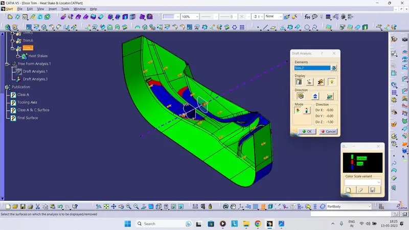
- Perform draft analysis to Now extract any surface and create a mid-point on it find whether the given axis clears the draft analysis. If not create a new tooling axis.
Tooling Axis
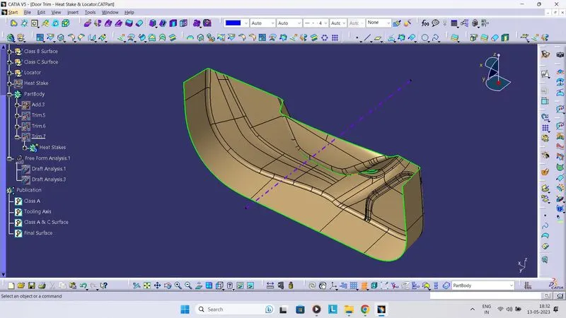
Step 2: Draft Analysis
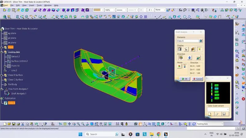
The Draft Analysis command enables you to detect if the part you drafted will be easily removed. This type of analysis is performed based on colour ranges identifying zones on the analyzed element where the deviation from the draft direction at any point, corresponds to specified values
- Before going to draft analysis go to customized view parameter >under mesh >check material and then click ok.
- Now for draft analyses go to insert » analysis » feature draft analysis.
- Use the compass to define the draft direction.
- In the colour scale change the draft angle to 3 degrees.
- If the component changes to green it indicates of passing draft angle.
- Use running point to check the angle on the component.
- The Draft Analysis is complete now.
Draft Analysis
Step 3: Creation of Class B Surface
- Offset the Class A Surface for 2.5 mm.
- Complete the Class B Surface using sweep and trim command.
- Apply fillets to the model after creating the entire surface.
Step 4: Creation of Class C Surface
- Extract the boundary from the Class A Surface using boundary command
- By using Sweep command create C Surface.
- After getting sweep then trim the output with class B surface to get final output.
- Now open part design workbench and using close body surface create a solid of the component.
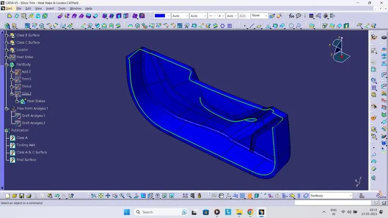
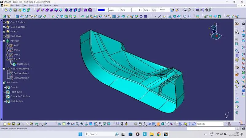
Final Surface
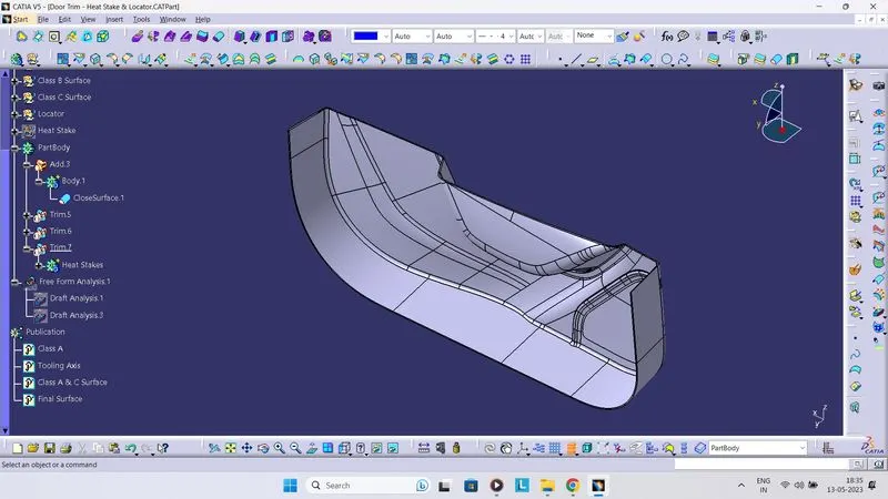
Step 5: Creation of Four Way Locator
- Create a 4-way locator using a sketch on the body and give proper constraints to make it Iso-constraint.
- After creating the sketch, pad it 20mm in height and thicken it to 1.3mm.
- Draft it with 0.5deg in the direction of the tooling axis.
- Give 3mm of chamfer with 45deg of inclination and a fillet of 3mm radius on chamfer. Give fillet of 0.5mm on all faces.
- Union trim the four way locator with the main surface defining the face to keep/ face to remove.
Four Way Locator Drawing
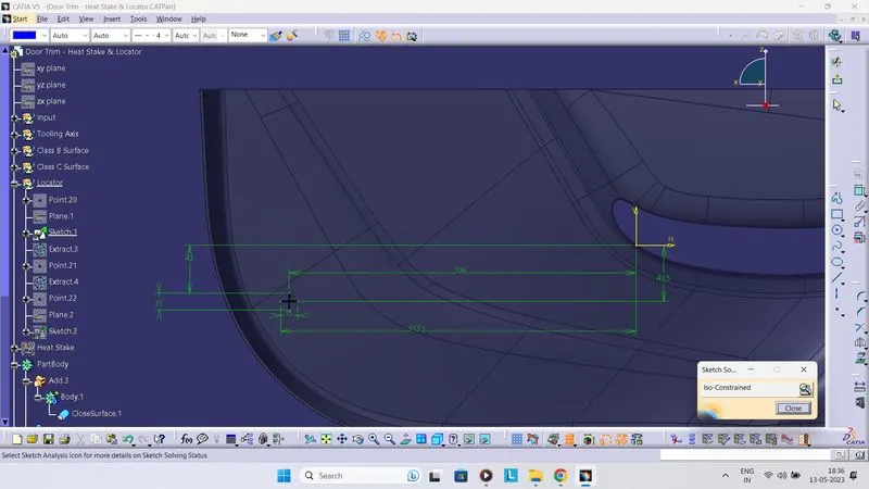
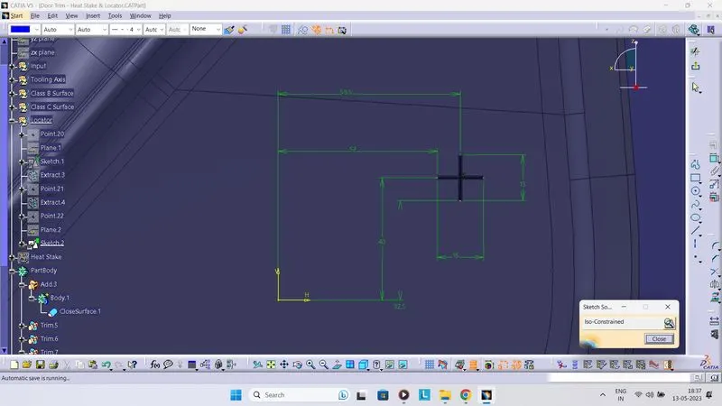
Four Way Locator
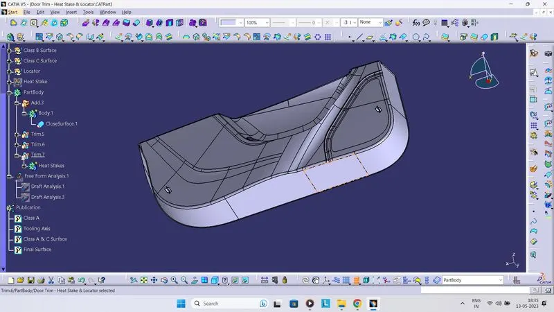
Step 5: Creation of Heat Stakes
- Create a heat stake using a sketch on the body and give proper constraints to make it Iso-constraint.
- After creating the sketch, pad it 15mm in height.
- Draft it with 0.5deg in the direction of the tooling axis.
- Translate the heat stake on all the given points.
- Union trim the heat stake with the main surface defining the face to keep/ face to remove to get the final output.
- Perform draft analysis with draft angle as 0.490.
Heat Stakes Drawing
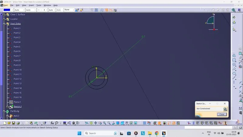
Heat Stakes
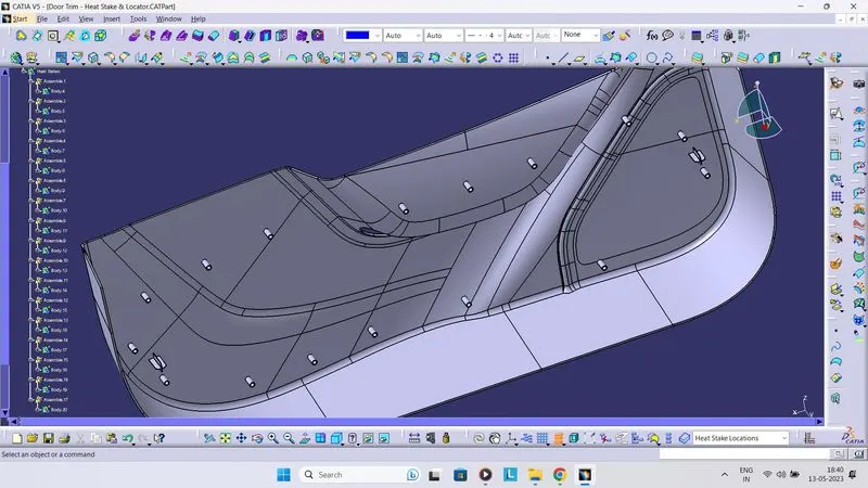
Isometric View
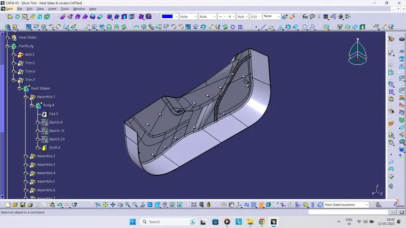
Multi View
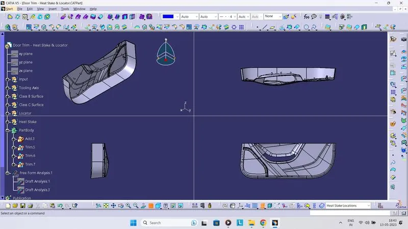
Draft Analysis for Final Surface