Hood design-Week 2
Introduction
Hood is main component of a car at the front portion. It is used to decorate the car & add luxurious look. The shape of the bonnet is made aerodynamic in order to minimize the air effect.
Hood Design Consideration
The hood of a car is considered as the frontal BIW enclosure component. Bonnets are designed to reduce air resistance as the air flows around the car. Apart from this, bonnets are also designed to meet several other requirements. They serve a great deal of purpose in protecting the passengers inside the car & the pedestrians in the event of an accident. It also acts as the cover for the engine.
- <!--[endif]-->The European New Car Assessment Programme (Euro NCAP) is a European car safety performance assessment program which has developed test specifications & rating systems for assessing pedestrian injuries during impacts with the front of vehicles such test includes a series of tests using impacts designed to bio-mimic a collision at speed of 40 km/h.
- <!--[endif]-->They describe a situation in which a pedestrian is situated laterally & a car first hits one of his legs. Test are conducted on the leg, upper leg & most importantly the head, as head trauma is most commonly responsible for casualties.
- <!--[endif]-->So, to avoid severe injuries to the head, the high impact area for adults & children are subjected to less thickness. Also, no reinforcement should be provided in that area as during head collision, the hood will absorb the head impact energy leading to collapse of the hood & thus protecting severe head injury.
Data to be used:
Hood Thickness Information
- <!--[endif]-->Outer Panel Thickness = 0.75mm
- <!--[endif]-->Inner Panel Thickness = 0.75mm
- <!--[endif]-->Reinforcement Thickness = 1.5mm
Parts provided for working
- Hood Skin Data
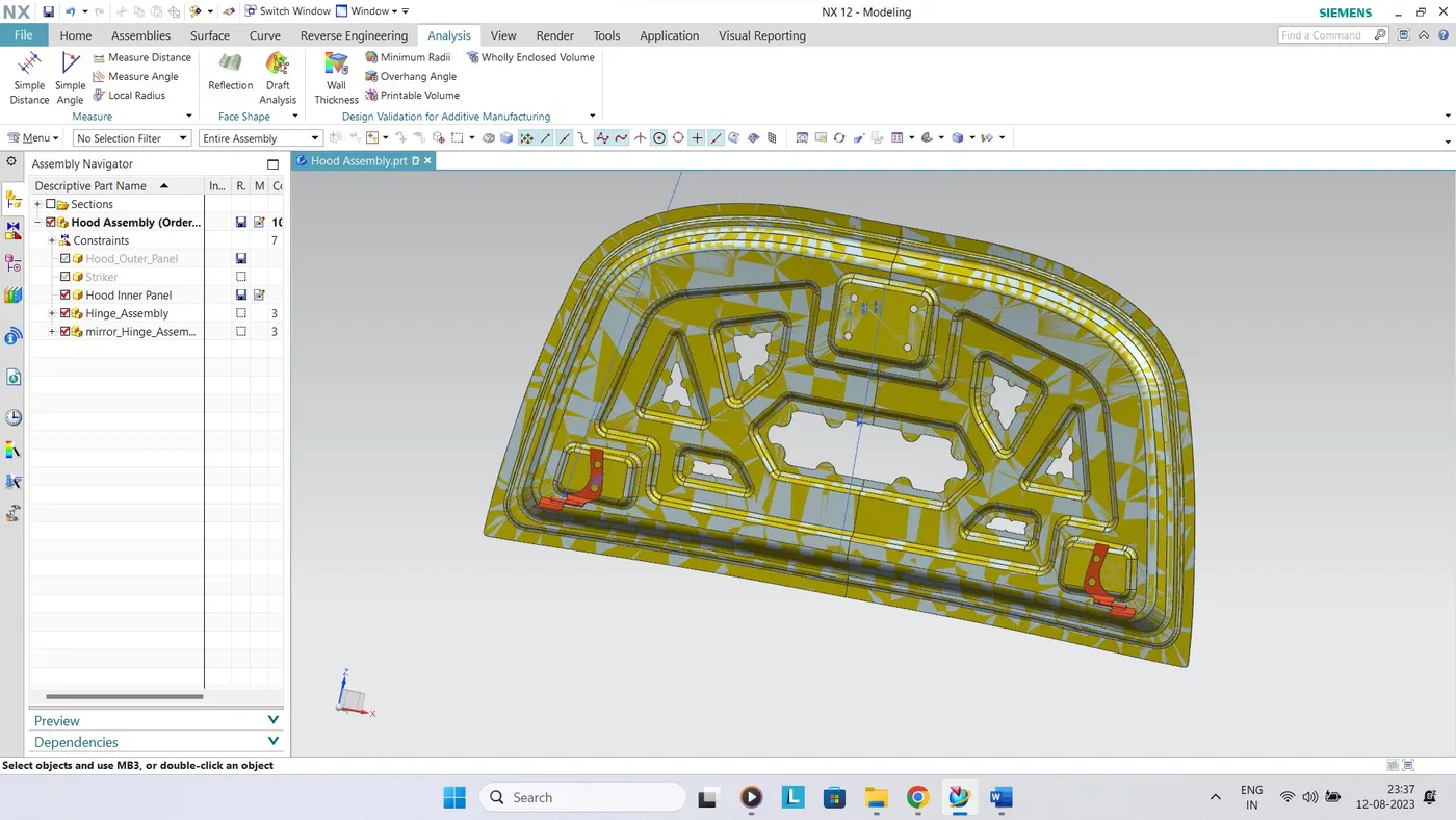
- Hinge Assembly
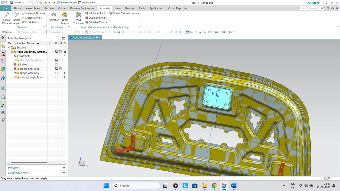
- Striker
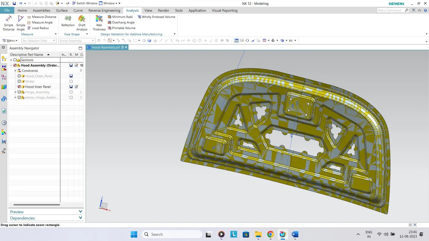
Inner Panel
In the inner panel only, we can research & implement the safety of pedestrians & as well as the driver. In this panel only we can attach the reinforcement, embossed, mastic points etc. It is an object of the present invention to provide a hood inner panel capable of reduction of a reaction force of the hood inner panel even if a level of deformation of a hood of a vehicle increases, & ensuring a sufficient energy absorption capacity.
Construction of Inner Pannel
- <!--[endif]-->Assembly was used to start the Hood.
- <!--[endif]-->Inner panel was named and by using Wave Geometry Linker the Inner panel was achieved.
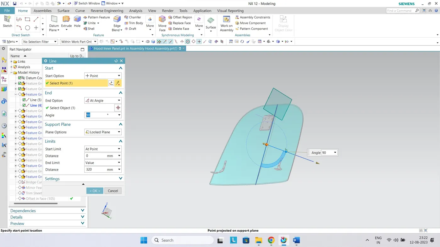
- <!--[endif]-->Tooling Axis was made which will be used later for other commands for giving direction.
- <!--[endif]-->Using Offset Command different flanges were made.
- <!--[endif]-->Using Through Curves the flanges were given the surface and by using sew all surfaces were joined.
- <!--[endif]-->By using Edge Blend all the surfaces were made smooth.
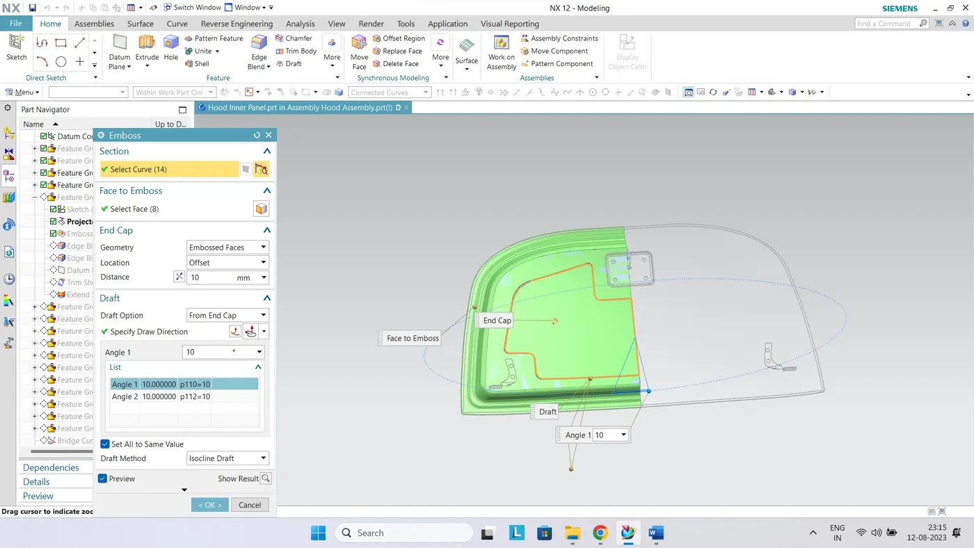
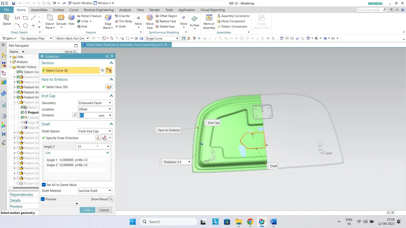
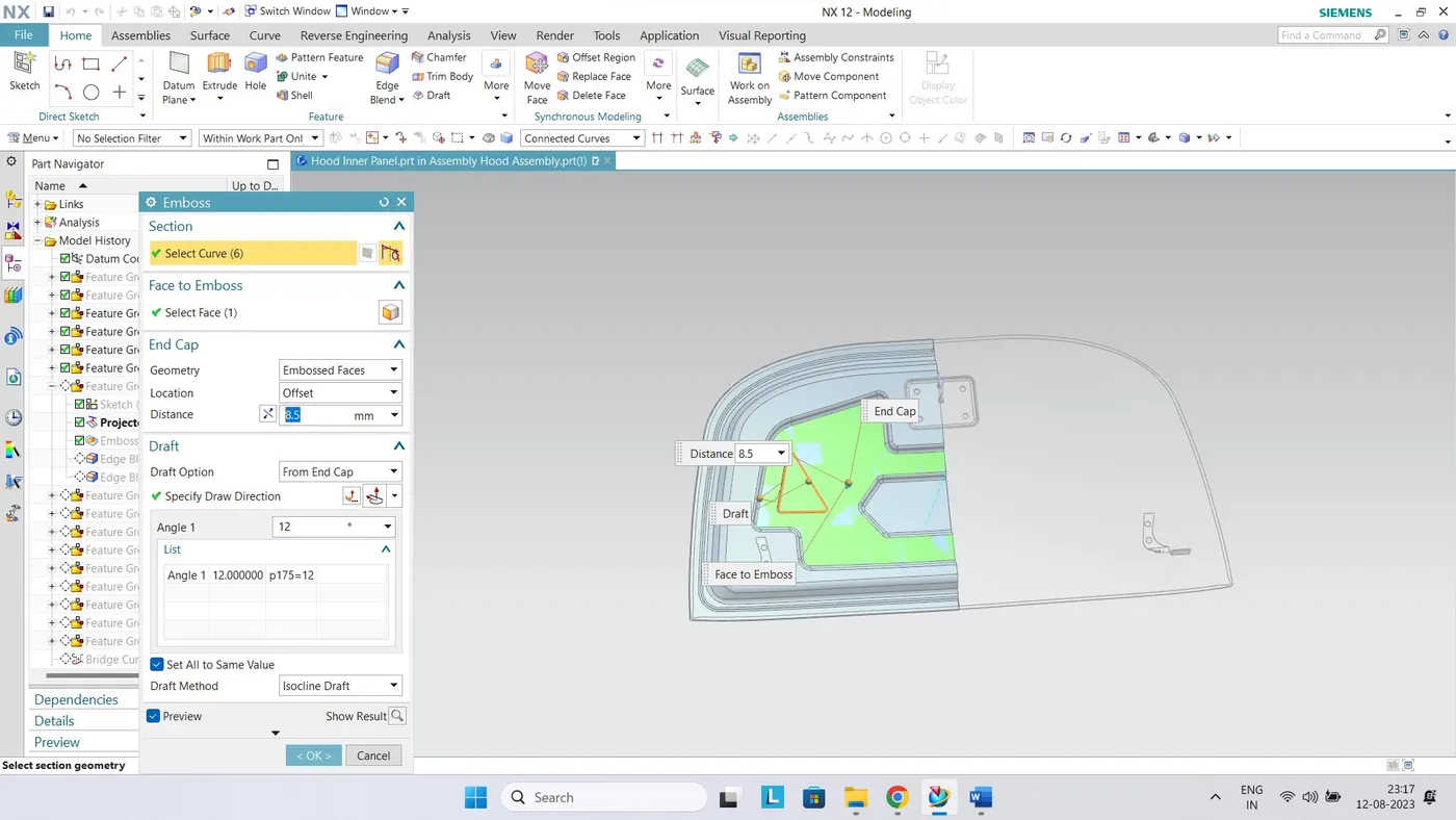
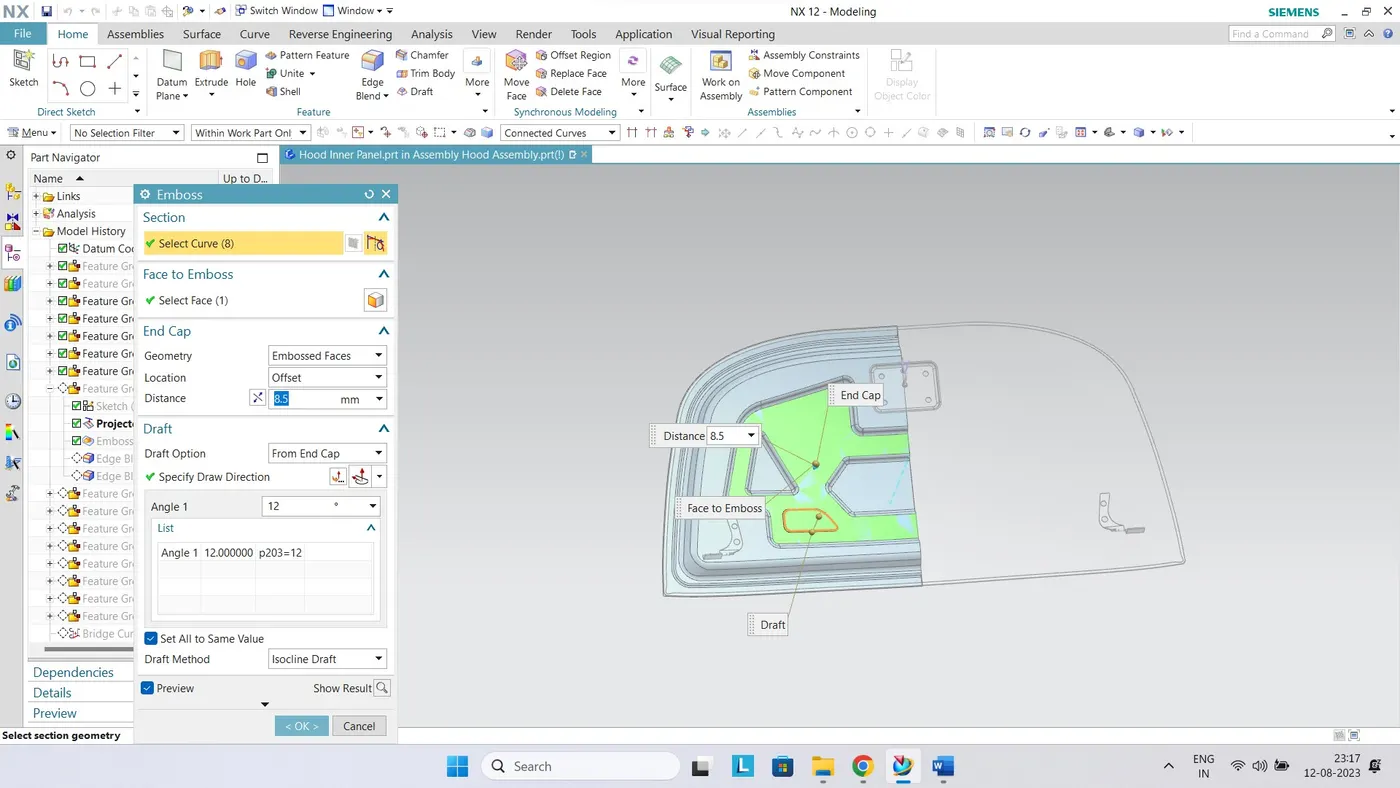
- <!--[endif]-->By using Emboss command for projected curve for the sketch emboss was made in tooling direction for 10mm at a 120.
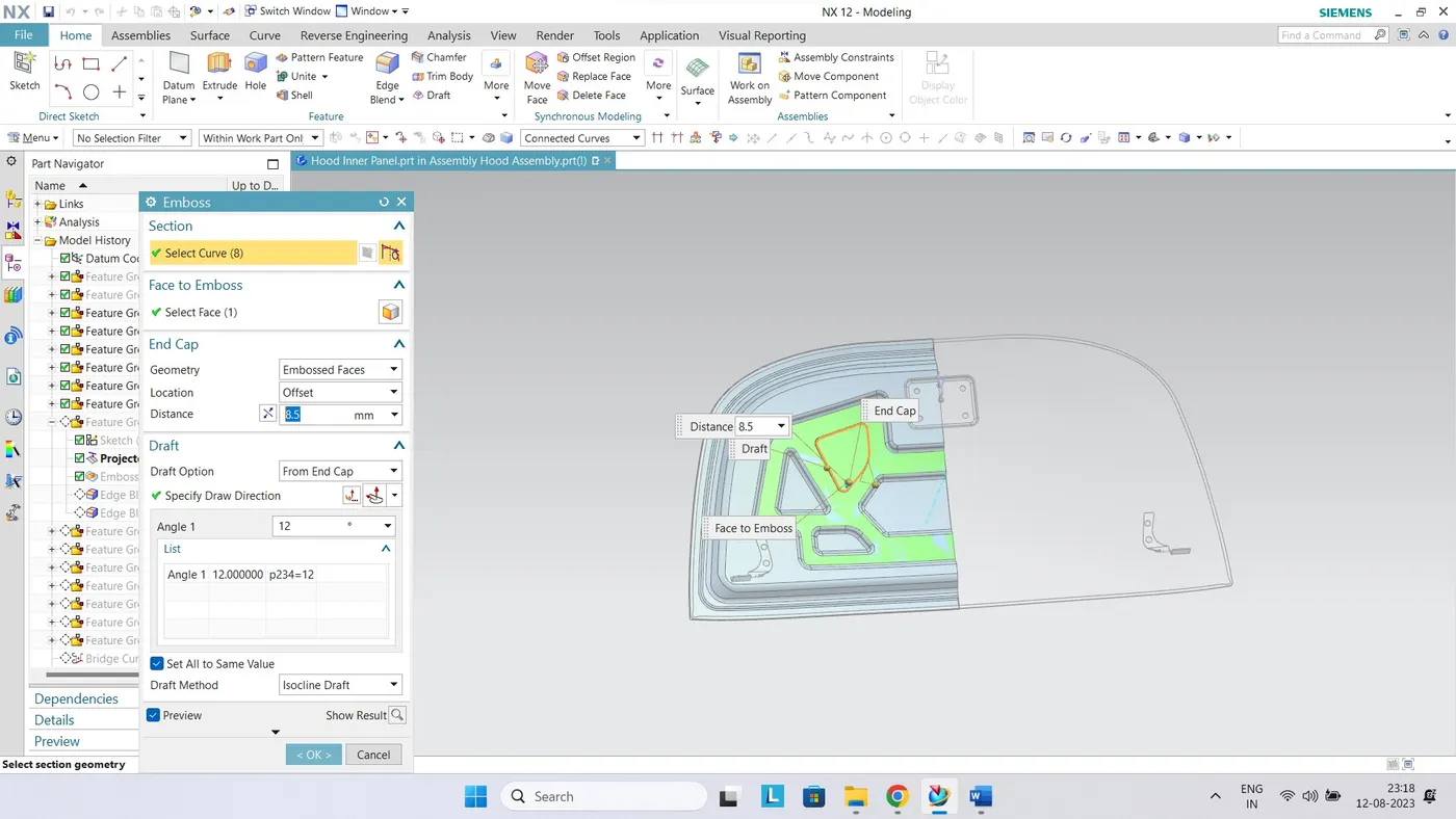
- <!--[endif]-->By using Emboss command again other emboss for projected curve for the sketch emboss was made in tooling direction for 8.5mm at a 100.
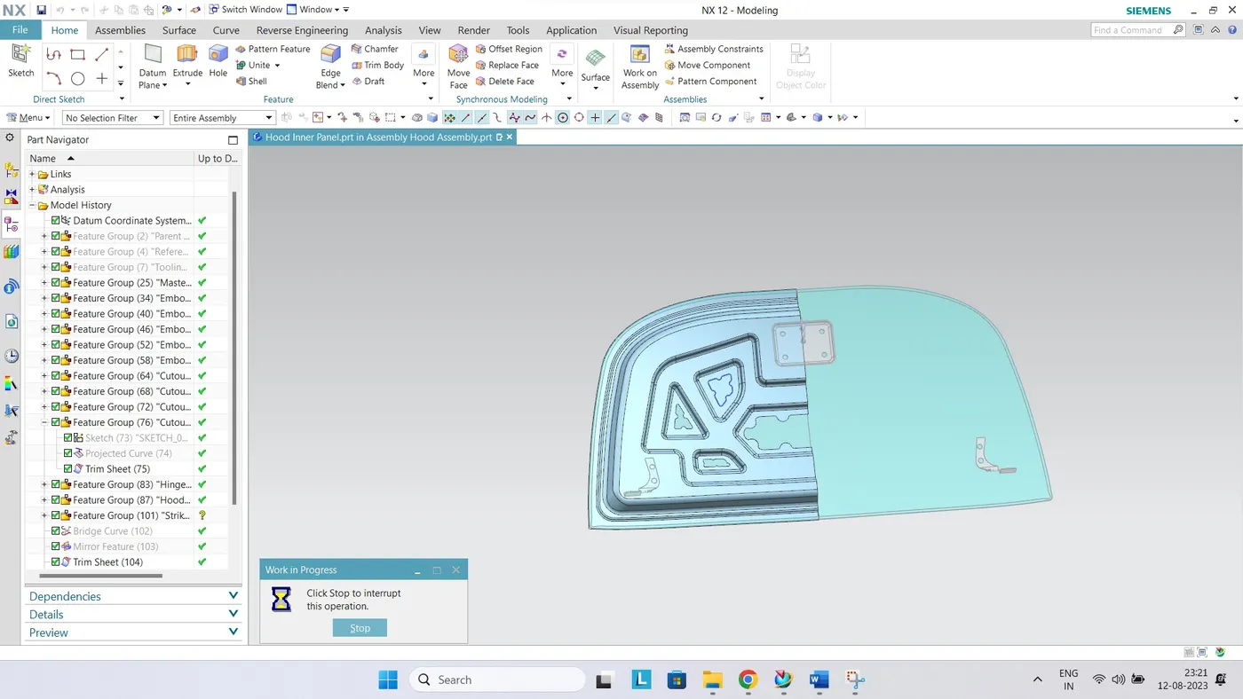
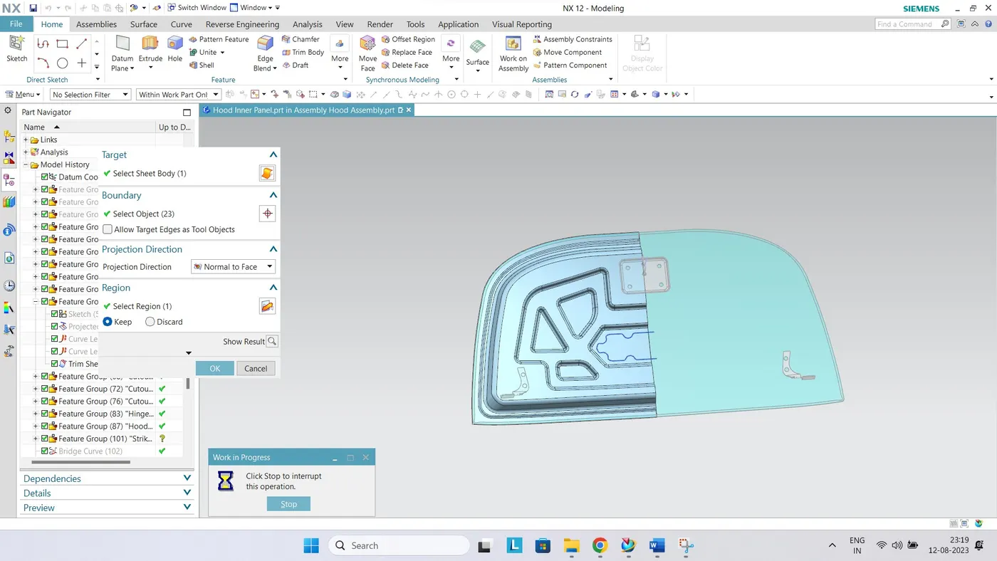
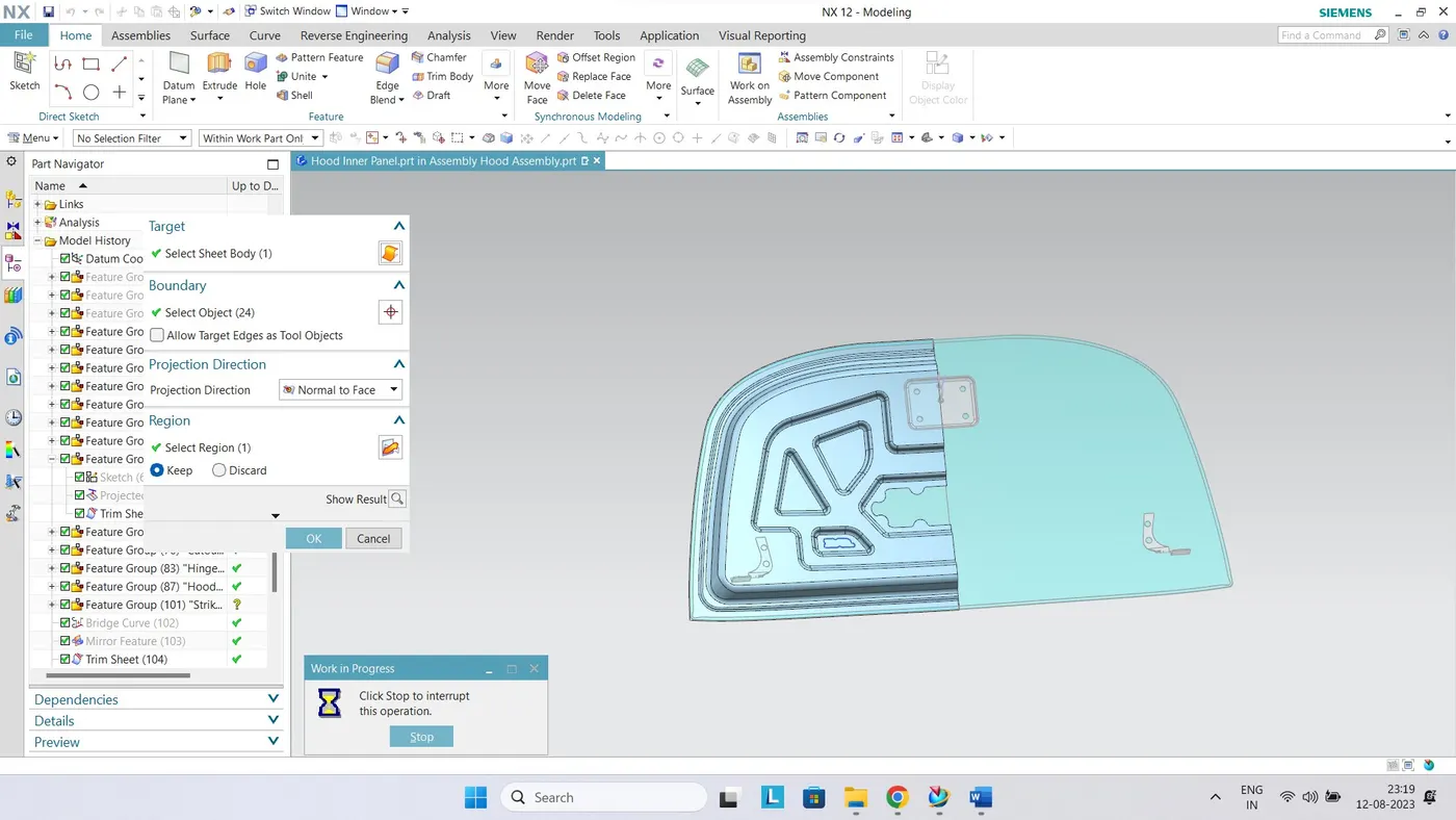
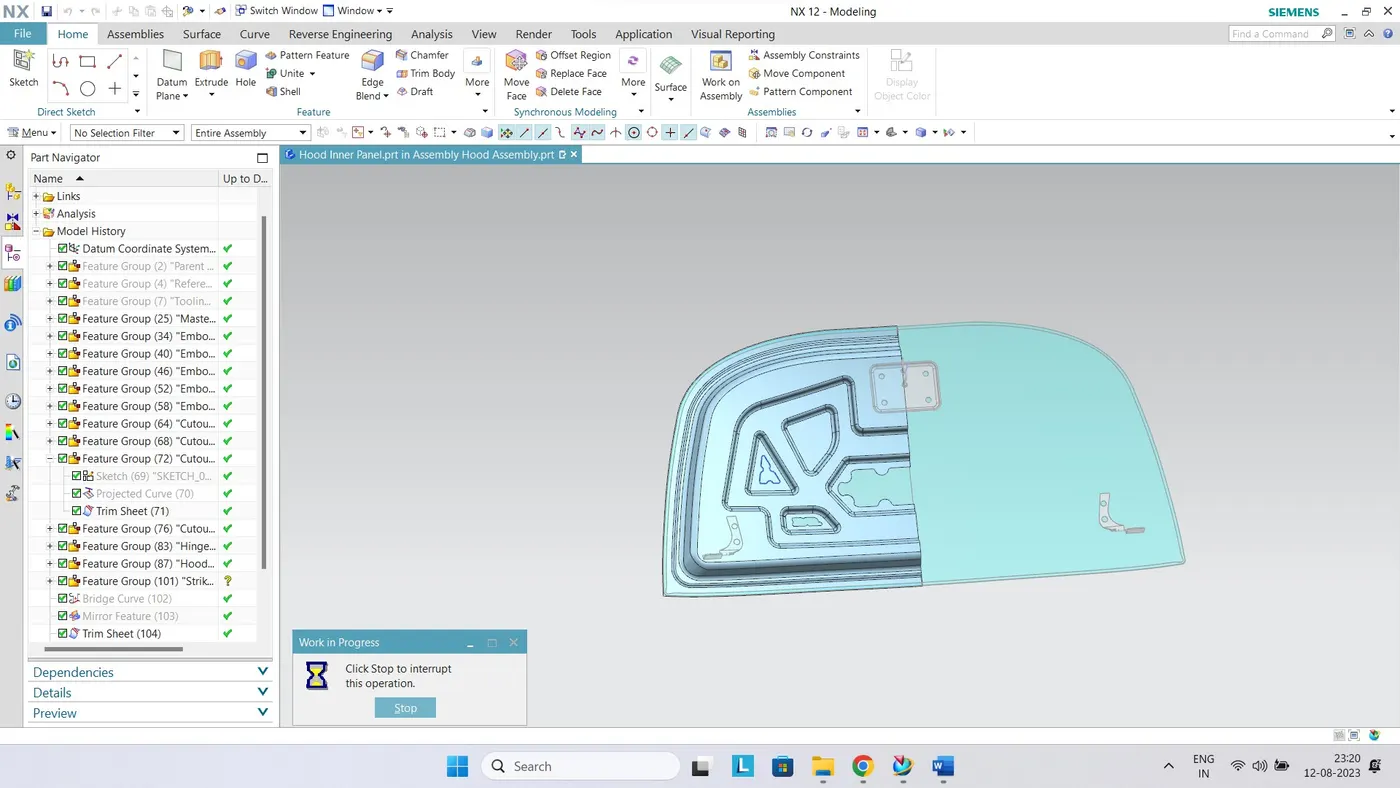
- <!--[endif]-->Cutouts are made for emboss using Project Curve and Trim Sheet command.
- <!--[endif]-->For Hinge assembly the mount is made using Emboss command.
- <!--[endif]-->Sheet is completed using sew command.
- <!--[endif]-->Using Assembly constraints and Mirror Assembly the Hinge Assembly was mounted on Hinge Mount.
- <!--[endif]-->Striker was mounted on striker mount using Linked Face, Law Extension and Trim sheet and Face Blend.
- Finally Thicken command is used to thicken for 0.75mm and completing the Inner Panel.
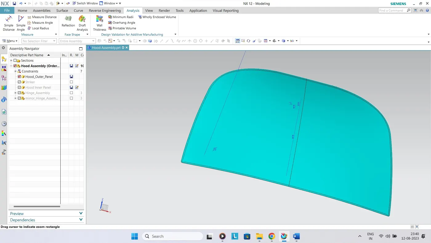
Outer Panel
We can also call it as cover of inner panel. It is the part, which gives luxurious look to the hood or bonnet. Outer & inner panel cannot join by any welding process like spot welding or rivet, which spoil the outer look of a car. The outer panel is generally extracted model from the prototype design. It is joined by hemming process.
Construction of Outer Pannel
- <!--[endif]-->Using Trim Sheet Command, the surface was trim in half for easy working.
- <!--[endif]-->Offset surface was used to achieve next surface for hemming.
- <!--[endif]-->Law extension was used to achieve the next perpendicular surface.
- <!--[endif]-->Using Three Face Blend the three surfaces were joined together into single surface.
- <!--[endif]-->Hem relief was given on the edges by using Curve on Surface and Trim Sheet command.
- <!--[endif]-->Using Mirror Geometry, the surface was complete in whole.
- <!--[endif]-->The Thicken command was used the thicken the component for 0.75mm.
Hinge Assembly
Hinge is a component that fixes the hood to the fenders of the car. The latch must be fixed perpendicular to the hinge axis so that the hood opens or closes properly.
Striker
Latch & striker is used for locking the hood with the car. It is usually placed on the space provided on the inner panel.
Process used for manufacturing of hood are:
<!-- [if !supportLists]-->· <!--[endif]-->Embossing
Sheet metal embossing is a stamping process for producing raised or sunken designs or relief in sheet metal. This process can be made by means of matched male and female roller dies, or by passing sheet or a strip of metal between rolls of the desired pattern. It is often combined with foil stamping to create a shiny, 3D effect.
<!-- [if !supportLists]-->· <!--[endif]-->Deep Drawing
The deep drawing process is a forming process which occurs under a combination of tensile and compressive conditions. A flat sheet metal blank is formed into a hollow body open on one side or a hollow body is formed into a hollow body with a smaller cross-section.
<!-- [if !supportLists]-->· <!--[endif]-->Punching
Sheet metal punching is a cutting process that involves applying sufficient shearing force to a sheet of metal to remove material. CNC punching can be used to produce a variety of holes and cut out shapes and sizes. The die has a cutout in the form of the desired function and is placed underneath the sheet. Punches move through the sheet metal, while dies on the other side of the metal piece act as a support, ensuring that the metal does not crack and that punches create precise and error-free holes.
<!-- [if !supportLists]-->· <!--[endif]-->Blanking
Blanking is a metal production process, during which a metal workpiece is removed from the primary metal strip or sheet when it is punched. The material that is removed is the new metal workpiece or blank. The process can be performed on any type of sheet metal where, due to punches and dies, metals are to be separated. During the metal blanking operation, the punches and dies work differently depending on the material and the tool steel ability to cope with the stresses that arise on the cutting edges.
<!-- [if !supportLists]-->· <!--[endif]-->Hemming
Hemming in sheet metal operations refers to the bending of a sheet metal edge onto itself. It is very similar to edge stitching in clothes. Similar to how an edge stitch strengthens the edge and makes it more durable, a hem imparts strength to the metal edge and improves its appearance. The edge of one part may also be folded onto another part to create a joint. Hemming is usually done in two stages. The first stage creates an acute bend using acute tooling (V die) followed by a flattening of the return flange using a flattening die.
Tooling Axis
Emboss
Cutouts
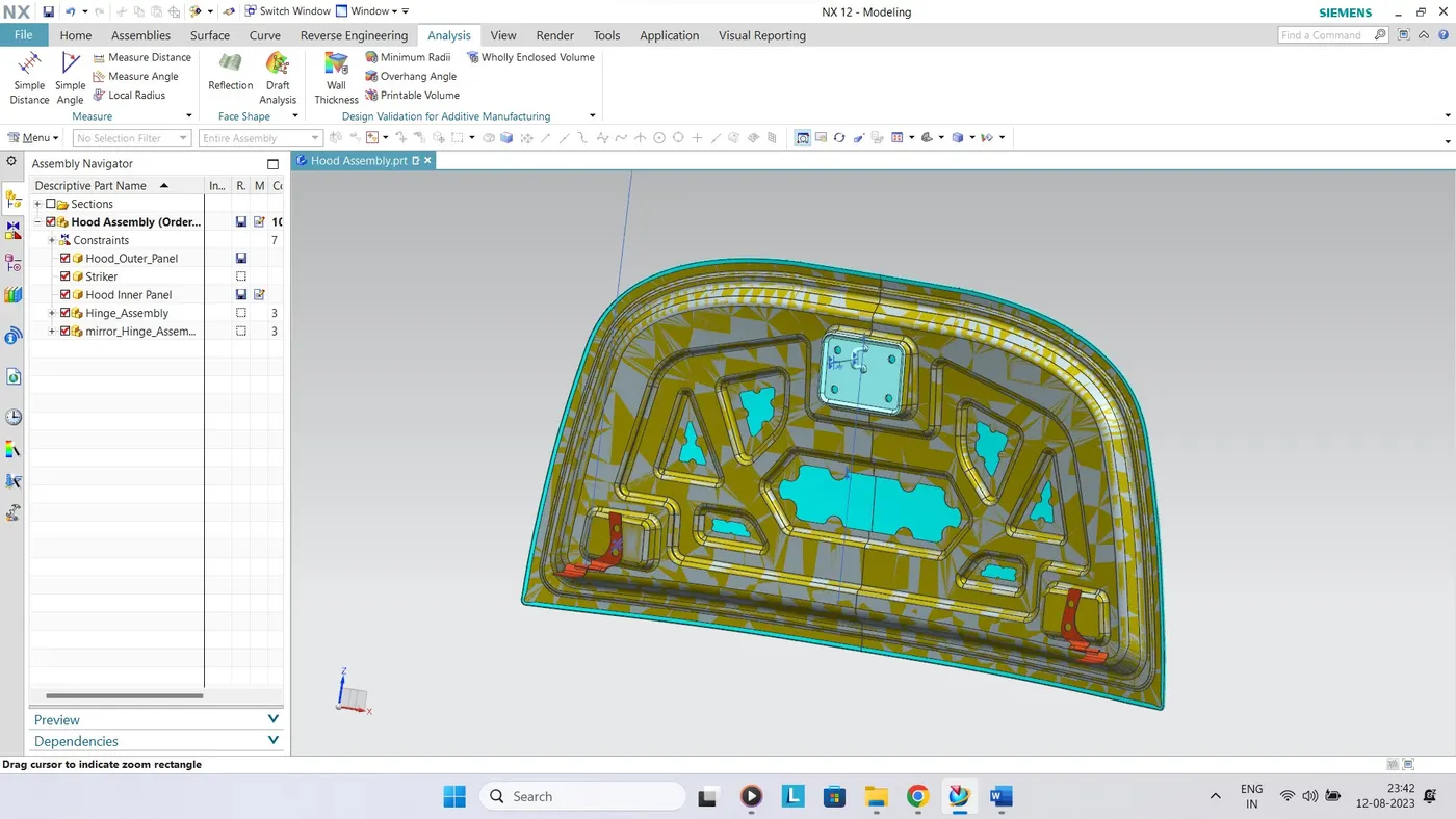
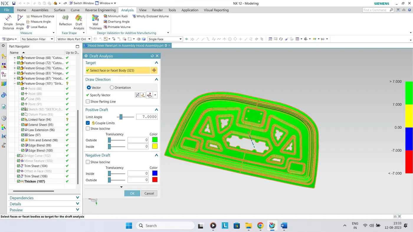
Draft Analysis
Inner Panel
Hinge Assembly
Striker
Outer Panel
Hood Assembly