Wiring harness design in CATIA V5 - 3D modeling Week 2 Challenge
Aim: Download following connectors & Connector clip cad data from given link & define it as Electrical Connector using Electrical Part design Workbench. Define all the necessary properties to Connectors & Clip.
1. Deutsch DT06 – 08SA ( https://www.te.com/usa-en/product-DT06-08SA.html)
2. Tyco 174357-2 (https://www.te.com/usa-en/product-2-174357-2.html?source=header-match)
3. Tyco 85229-1 (https://www.te.com/usa-en/product-85229-1.html?q=85229&source=header)
Wiring Harness
The wiring harness is the combination of electrical cables, or assembly of wires, that connects all electrical and electronic (E/E) components in the automotive vehicle, like sensors, electronic control units, batteries, and actuators. The wiring harness handles the energy and information flow within the E/E system to fulfil primary car functions, such as steering and braking as well as secondary car functions, such as ventilation and entertainment.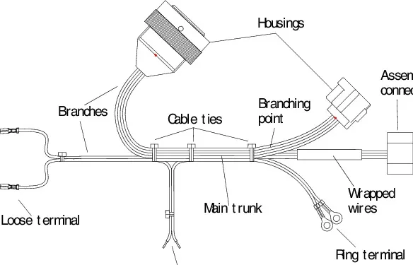
Connector
Components of an Electrical Circuit are electrically connected if an Electrical Current can run between them through an Electrical Conductor. An electrical connector is an electro mechanical device used to create an electrical connection between parts of an electrical circuit, or between different electrical circuits, thereby joining them into a larger circuit.
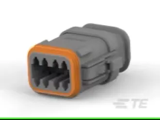
Cavity
Made from thermoplastic, they help secure the mounting of the connectors under the hood of a vehicle or on the chassis.
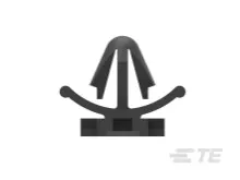
Deutsch DT06 – 08SA
Connector Connection Point
- Create midpoint on the contact face which will be normal to wire bundle insertion.
- Create Axis System with respect to the point which we have created and defining the axis direction.
Bundle Connection Point
- Define the part as connector in Catia, give number of terminations as 8 because we have 8 entry points for wire.
- Define Bundle Connection Point.
- Define Connector Connection Point.
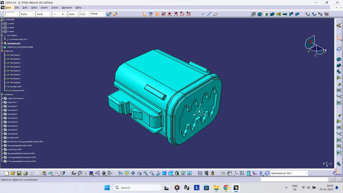
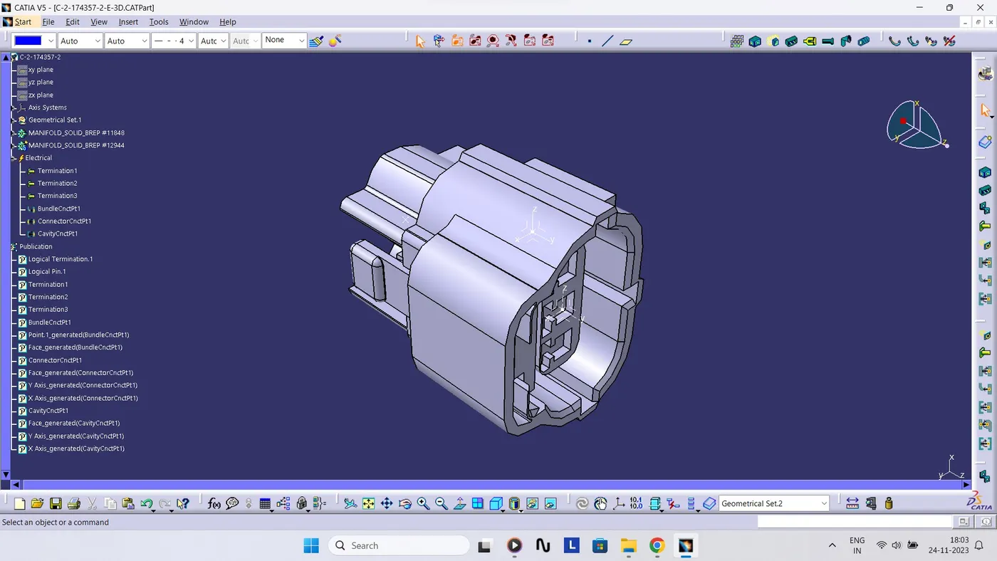
Tyco 174357-2
- Create midpoint on the contact face.
- Create Connector Connection Point.
- Create Connector Connection Axis System with respect to the point which we have created and defining the axis direction.
- Create Cavity Connection Point.
- Create Cavity Connection Axis System with respect to the point which we have created and defining the axis direction.
- Define Connector Connection Point and Cavity Connection Point.
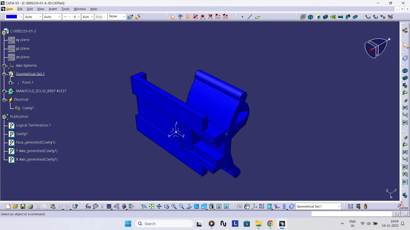
Tyco 85229-1
- Create Cavity Connection Point.
- Create Cavity Connection Axis System with respect to the point which we have created as same as created in the connector and defining the axis direction accordingly.
- Define Cavity Connection Point.
Electric Assembly Design
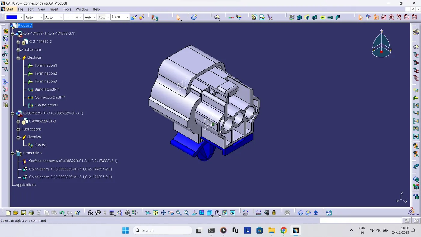
- Select from Start Menu in Catia Equipment and System then select Electrical Harness Discipline Menu from the sub menu select Electrical Assembly Design.
- Add existing component and import connector and cavity in the assembly.
- Define Constraints by selecting Connect Electrical Device.
- Select Connector and Cavity Clip to make the connection between them.
Conclusion
The connection between Connector and Cavity Clip is successfully established in Electrical Assembly Design.
Reference
https://www.synopsys.com/glossary/what-is-wiring-harness.html
https://www.researchgate.net/figure/Typical-wiring-harness-terminology-and-components_fig1_265603671
https://en.wikipedia.org/wiki/Electrical_connector
https://www.te.com/usa-en/product-DT06-08SA-CE13.html?source=header-match