Week 9 - Challenge 2 - Switch Bezel Design
Aim: The objective of the project is to design the switch bezel and to do a draft analysis for it by creating the required tooling direction with the help of Bisecting method.
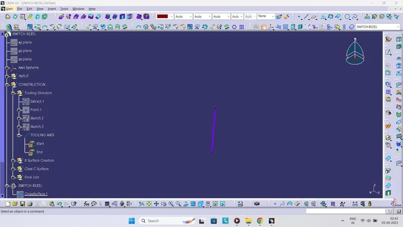
STEP 1: Creation of Tooling Axis
- The base surface of the Class–A was extracted and a point at the centre is created and an axis system was inserted into the topic with the current feature disabled.
- Then, using project intersection along yz plane is created and the two inclined lines were drawn inside the positioned sketch.
- Then bisecting lines with the two inclined lines were drawn.
- Now the same procedure is done along the xz plane but on one side we don’t have inclined lines so the centre point is used to extrude a line along the z-direction and gave a measurement of 6 degrees (tentatively).
- With these two lines from sketches 1 and 2, the bisecting line is created and published as Tooling Axis (tooling direction).
Tooling Axis
STEP 2: Creation of Class-B Surface
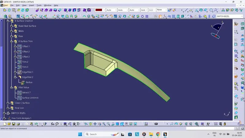
- For creating the Class-B surface the required surface except the offset surface have been extracted and then untrimmed all the surface.
- Then all the surfaces have been extrapolated to get intersections between them.
- Since the thickness of the Switch bezel is 2.5mm the B-Surface was offset to 2.5 mm and the required trim operations must be carried out.
- To get the radius of fillets the filleted surface is extracted and untrimmed the surface and then the radius is measured.
- Finally, the required corners have been filleted to 12.5mm (15mm-2.5mm)15mm fillet value of A-Surface.
- To get the radius of fillets the filleted surface is extracted and untrimmed the surface and then the radius is measured 2.5mm thickness of the component and 11.5mm(14mm-2.5mm).
Class-B Surface
STEP 3: Creation of Class-C Surface
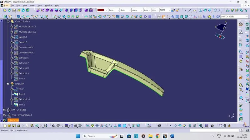
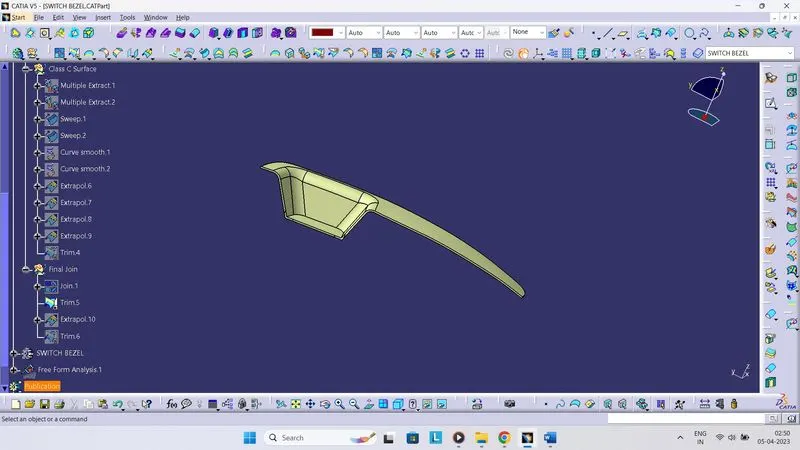
- The required outer edges of the A-Surface were extracted using Multiple Extract. Then to avoid the patches the curve is smoothened using the Curve Smooth option.
- Then by using the sweep command the surface was created.
- Then, using extrapolate command, the edges were intersected between the surface corners, which eases the trimming operation.
- Now the required portion of the C-Surface was trimmed out.
Class-C Surface
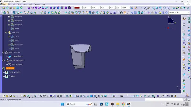
STEP 4: Creation of Closed Surface
- Now the Class-A and Class-C surfaces were joined together by removing the gaps in between them with the help of extrapolation (tangent continuity) and trim surface.
- Then the exact surface of the Switch bezel was trimmed from the above-resulted trim surface with the Class-B surface.
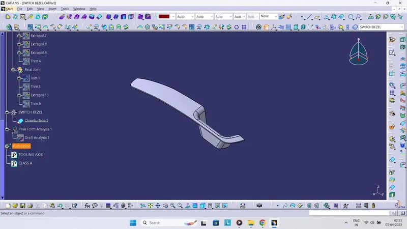
- Then, by defining the part body by using the Closed Surface command in Part Design, the component's solid body is created.
Final Component
STEP 5: Draft Analysis
- First the Class-A – Surface is checked before creating the Class –B & C surface and finally the solid body must be analyzed. Both can be done by following the below procedures.
- By changing the view mode to custom view parameters – Material mode then the feature draft analysis is enabled.
- Then the compass was activated and placed with the tooling axis by dragging the red pointer and then locking it.
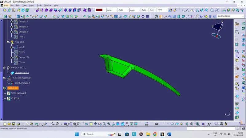
- Then, by selecting the quick analysis mode, the nominal value will be 3 degrees and checked for the component's draft angle.
- The green colour area shows that it satisfies the 3-degree draft angle. If not satisfied then by using the Running point tool the area is measured and then altered to get a successful draft for the created tooling direction.
Draft Analysis
Front View
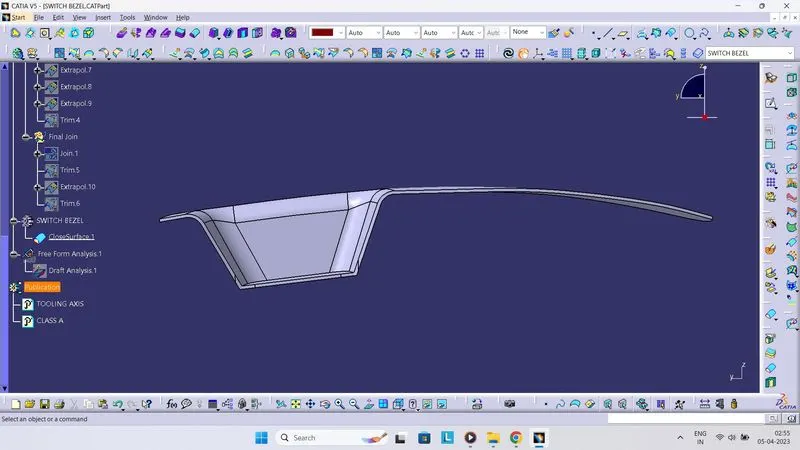
Top View
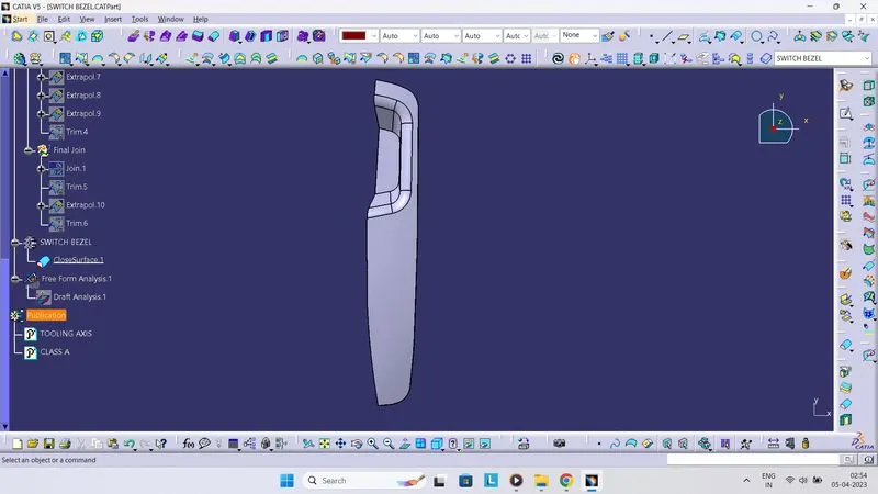
Side View