Advanced Sheet Metal Design Using NX Cad Challenge_2_Box Assembly
Project: Advanced Sheet Metal Design Using NX Cad Challenge_2_Box Assembly.
Introduction
Sheet Metal is metal formed by an industrial process into thin, flat pieces and it can be cut and bent into a variety of shapes. Sheetmetal is a comprehensive cold working process for metal sheets usually below 6mm, including shearing, punching/ cutting/ folding, riveting, splicing, etc.
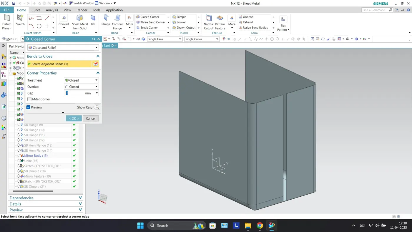
In the Sheet Metal application, we can create uniform thickness sheet metal parts using basic features such as flanges, tabs, and jags. We can also do close corners, cutout, and stiffening features.
Process
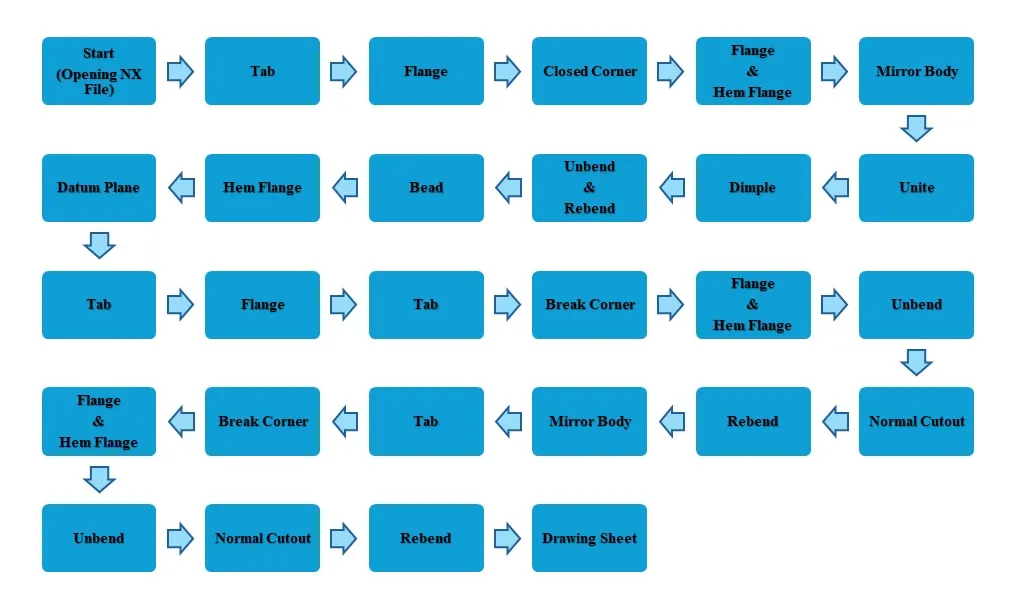
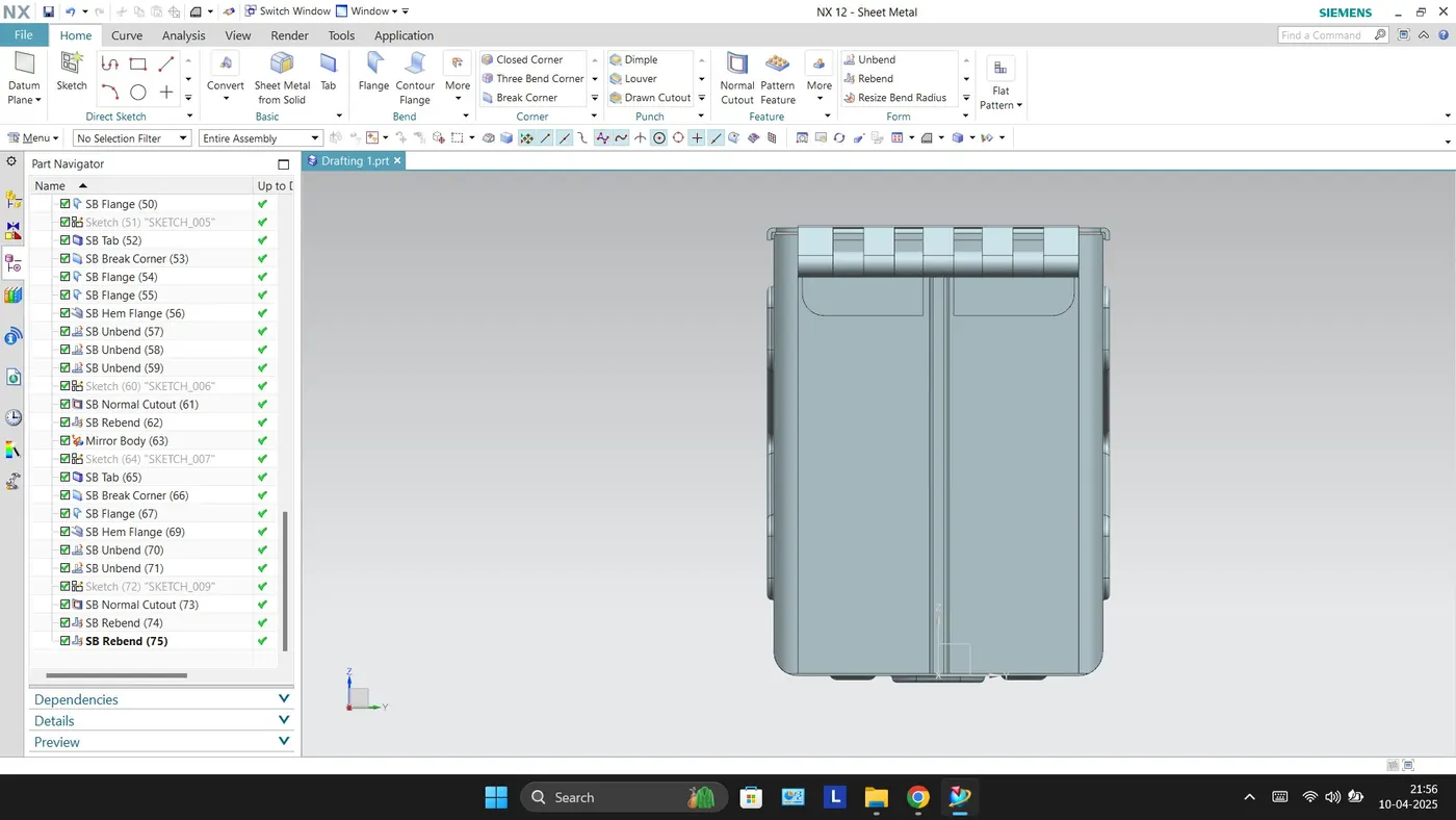
The sheet metal casing has been designed with the below mentioned flow chart process. While designing the Box Assembly the default thickness, bend radius, relief depth, and relief width value are set to 1mm.
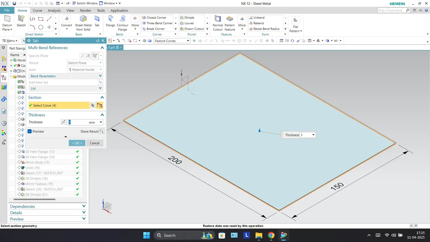
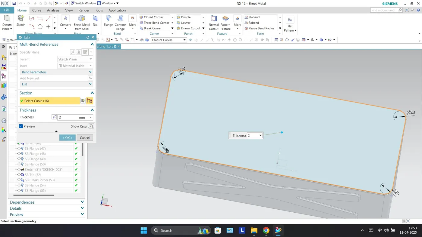
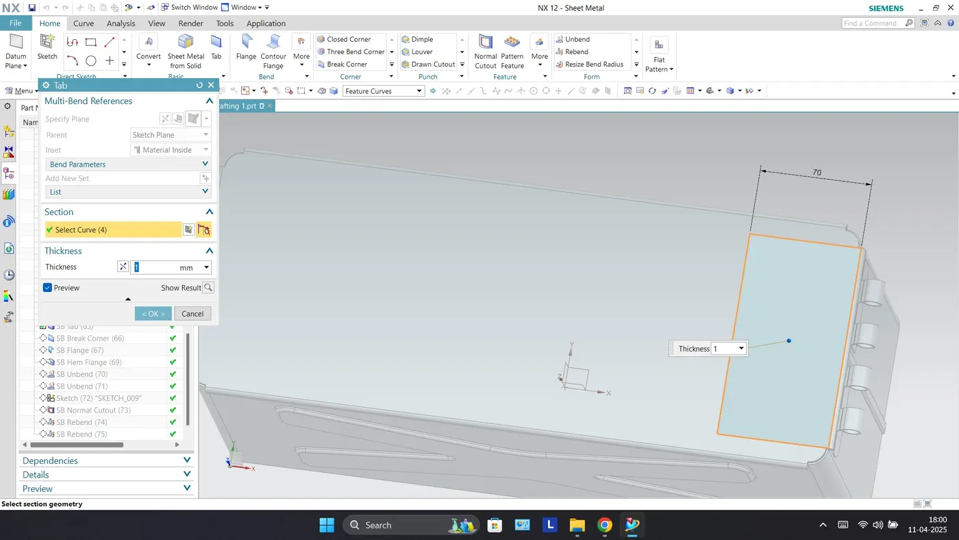
Tab - The Tab feature creates a base feature by extruding a sketch along a vector by a thickness value, or adds material to the planar face.
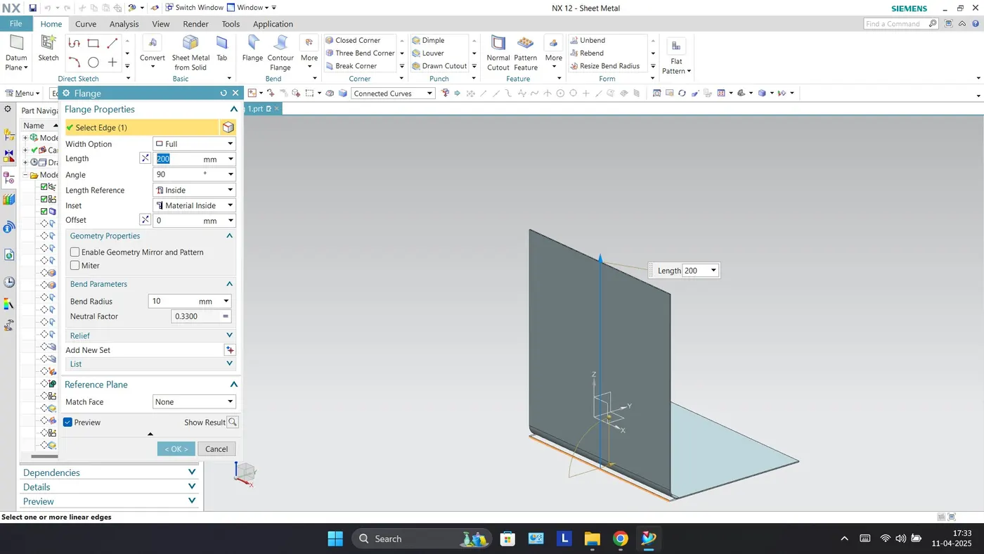
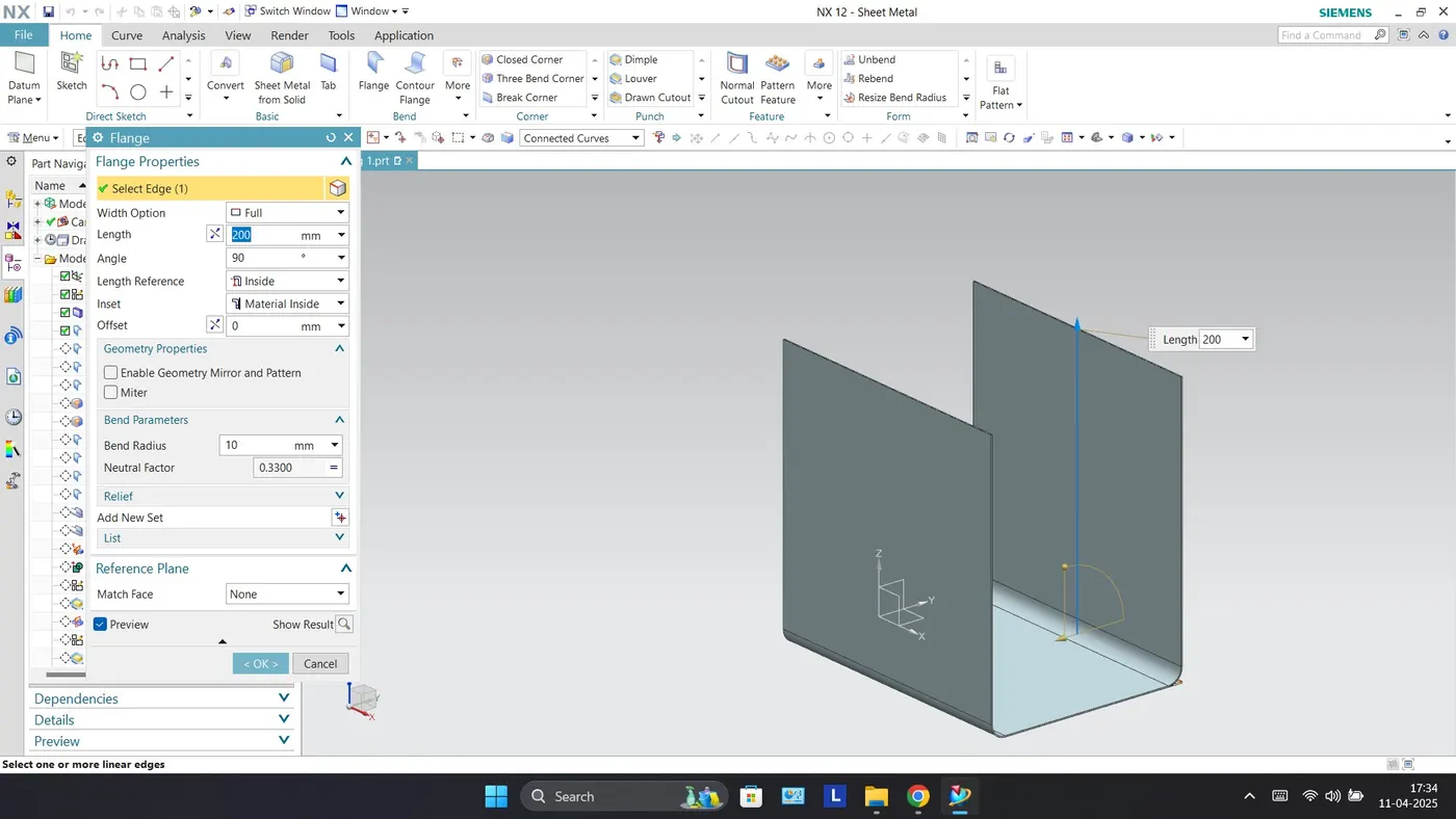
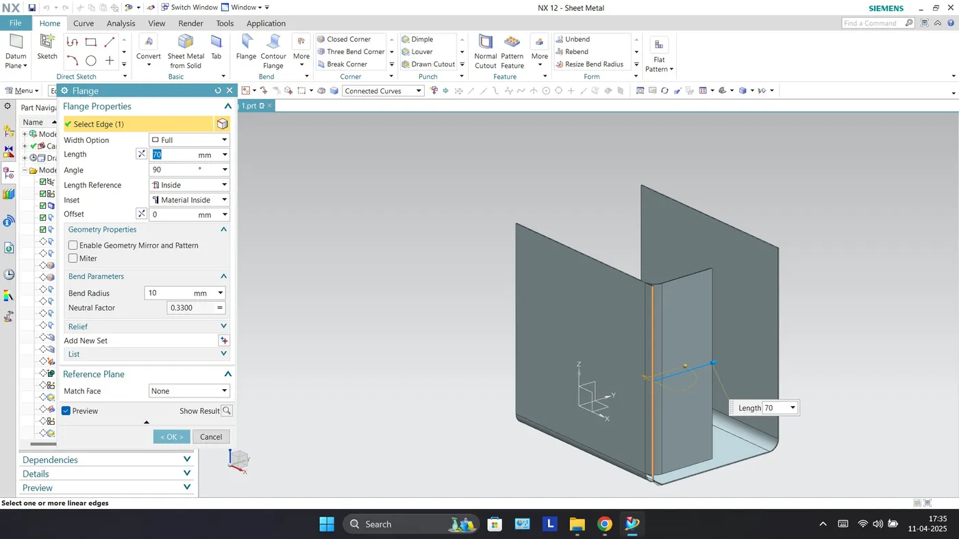
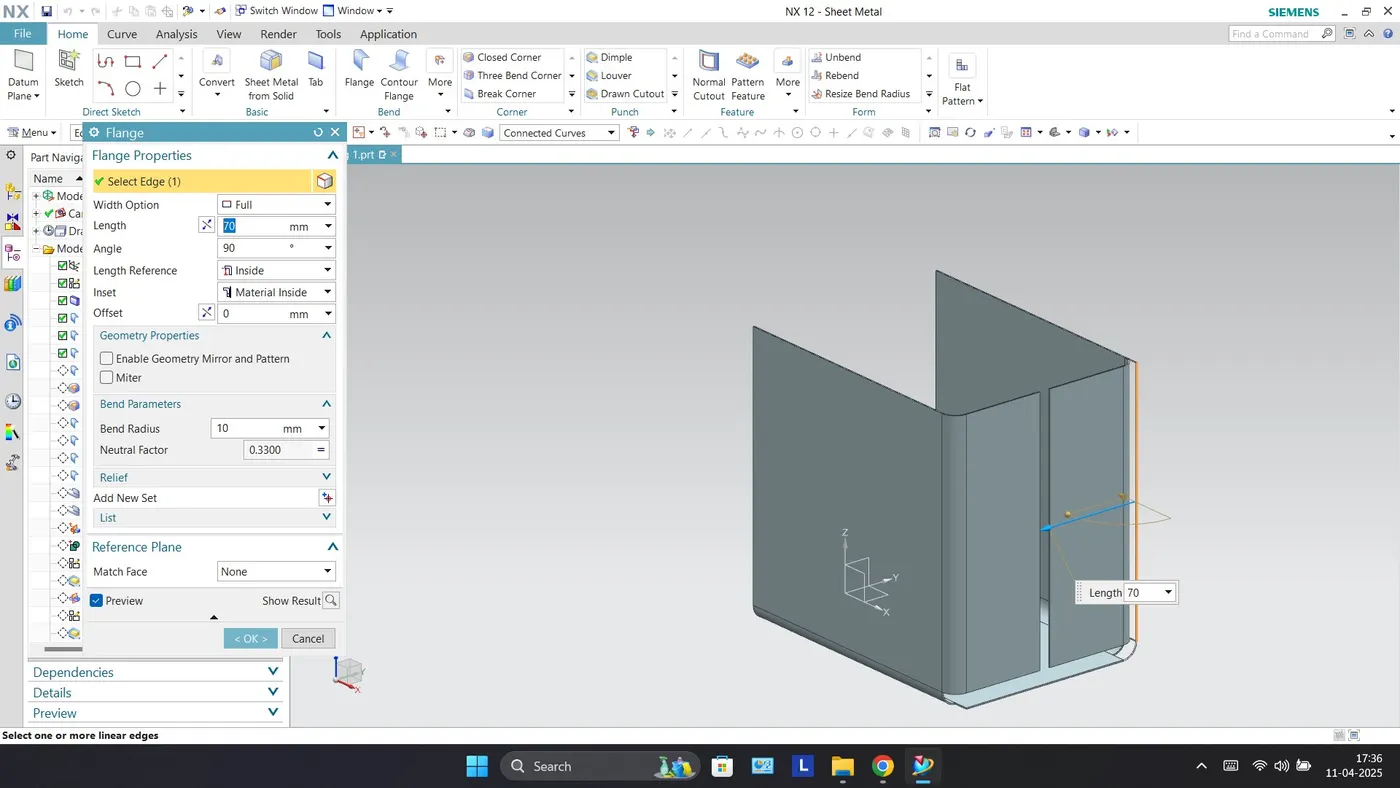
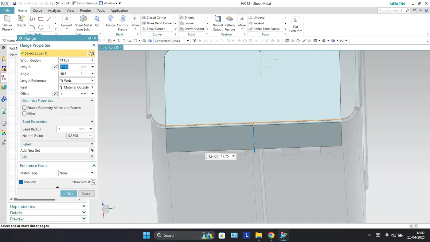
Flange - The Flange feature adds a flat flange at an angle to the planar face and adds a bend between the two. While creating flange we have to set different parameters such as length of the flange, its angle, length reference (Inside, Outside and Web), inset (Material Inside, Material Outside and Bent Outside). Other parameters like Bend Radius, Bend Relief, and Neutral factor are also needed to be considered.
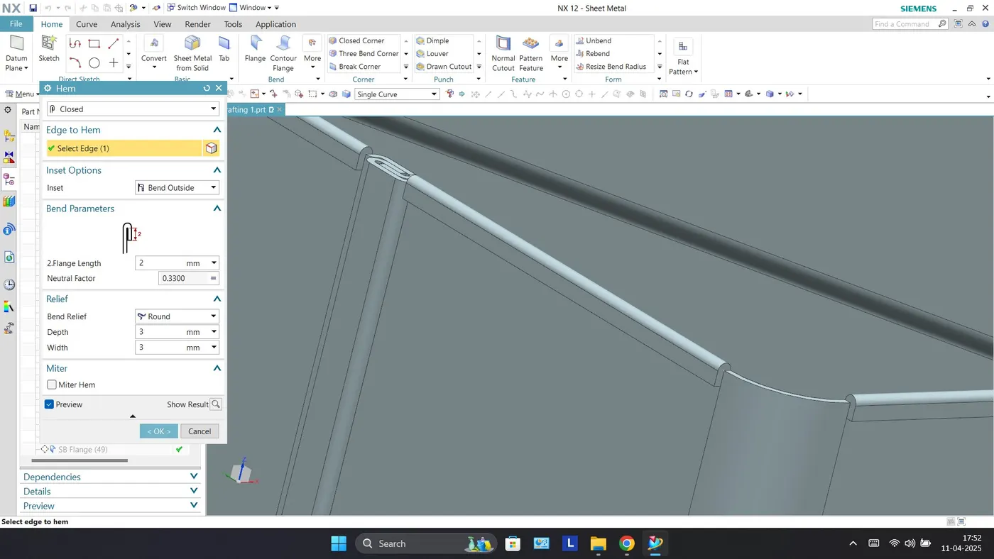
Hem Flanges - Hem flange feature is used to modify the model by folding the edge of a flange. The main purpose of this feature is to increase the stiffness and for safe handling.
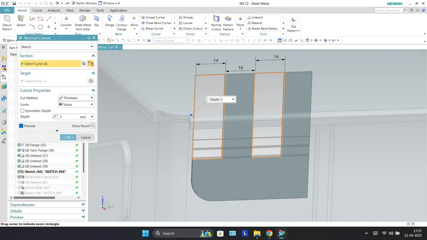
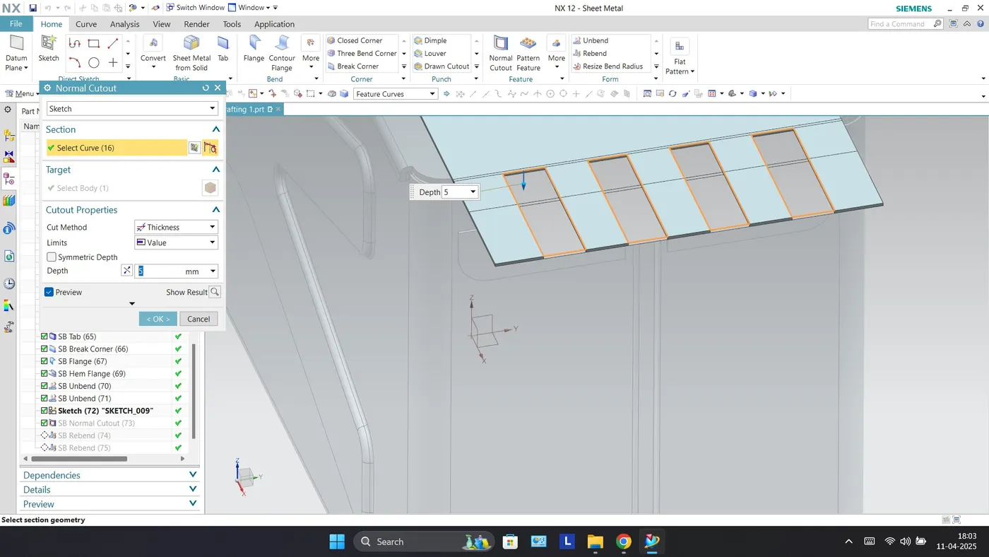
Normal Cutout - The normal cutout feature cuts the material by projecting a sketch onto the model and then cutting perpendicular to the faces intersected by the projection.
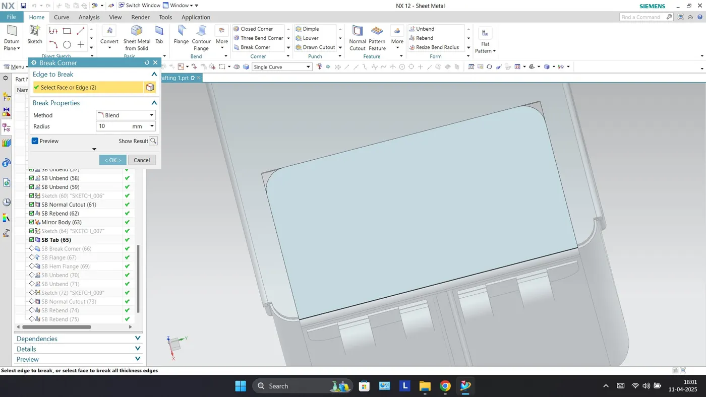
Break Corner - It creates Rounds or chamfers in a sharp corner of a tab or a flange.
Dimple - This feature is used to lift an area of the model inside a sketch that simulates a stamping tool. The Dimple command makes an indentation in the sheet metal part, using a sketched section as its outline.
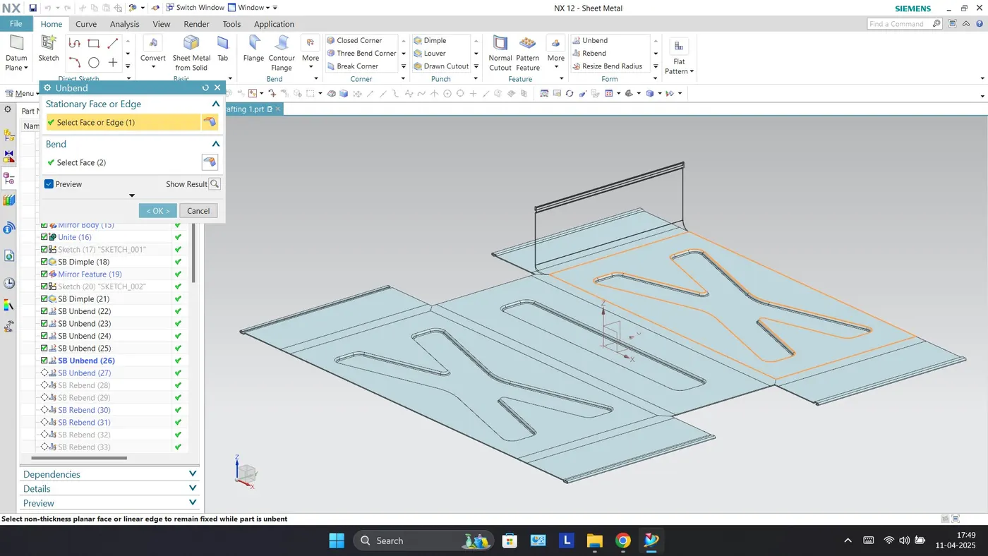
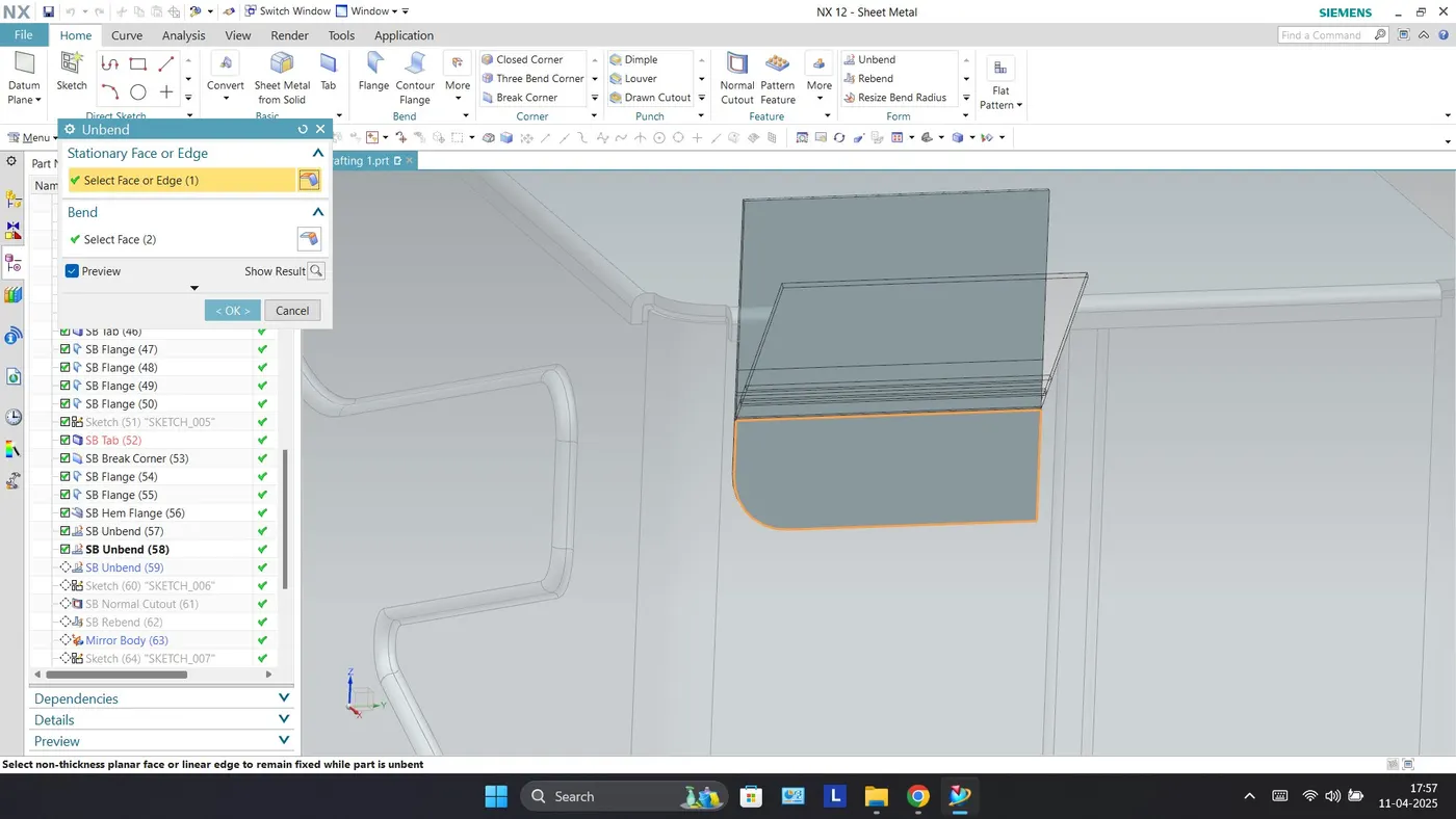
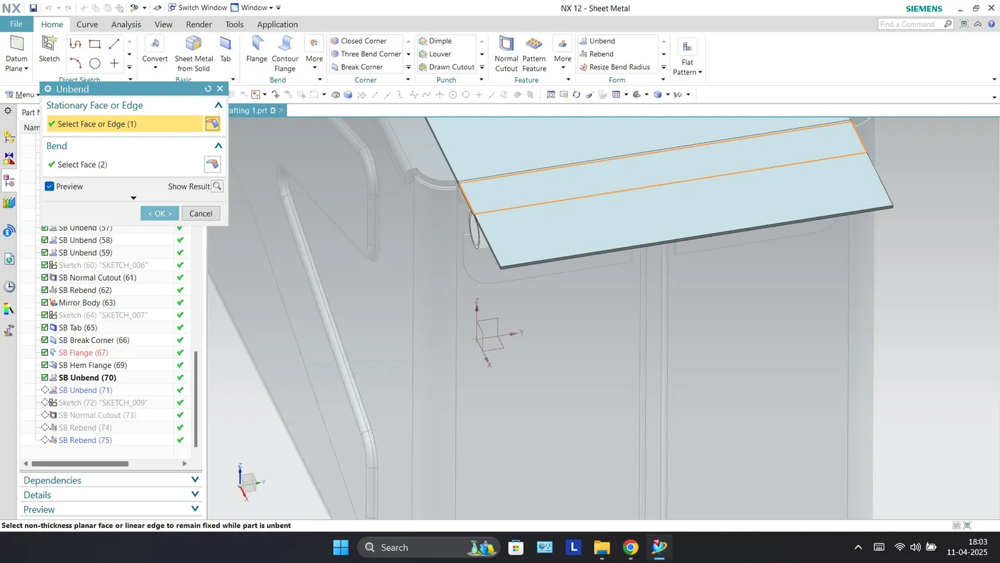
Unbend - This command is used to unbend the sheet metal. The punching operation can be performed only by unbending the sheet metal.
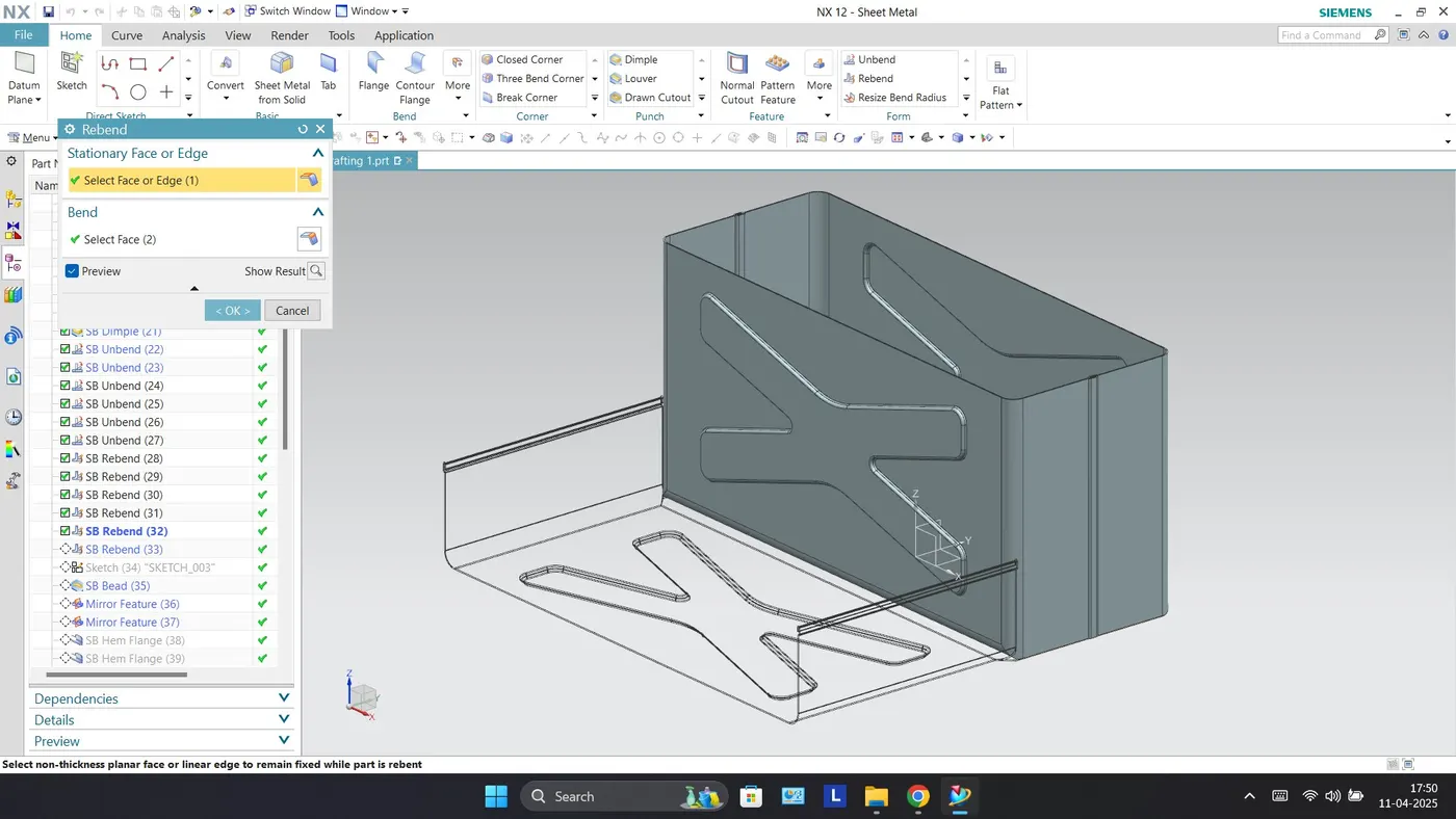
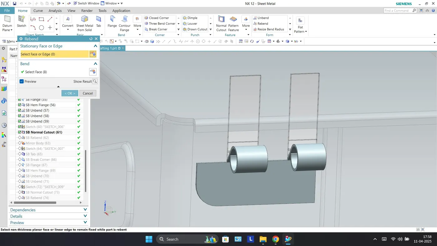
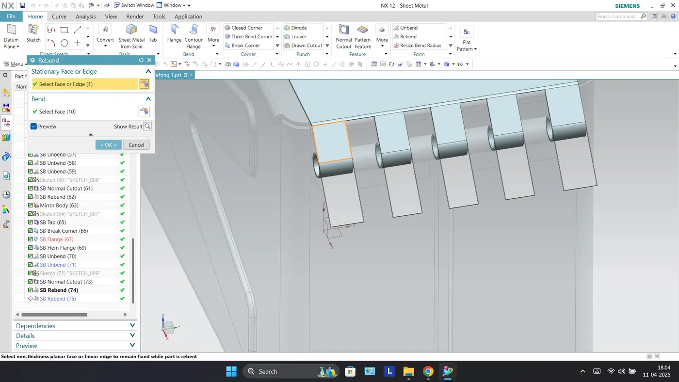
Rebend - Rebend feature is used to get the original bend shape after performing operations like a dimple, bead, etc. It's a tool to get the flanges of the sheet metal body into its original position that flattened with unbend tool to create some some complex structure on the sheet metal body.
Bead - Bead is another punch tool used to create embosses over the sheet metal body w.r.t. the sketch created in the specific plane.
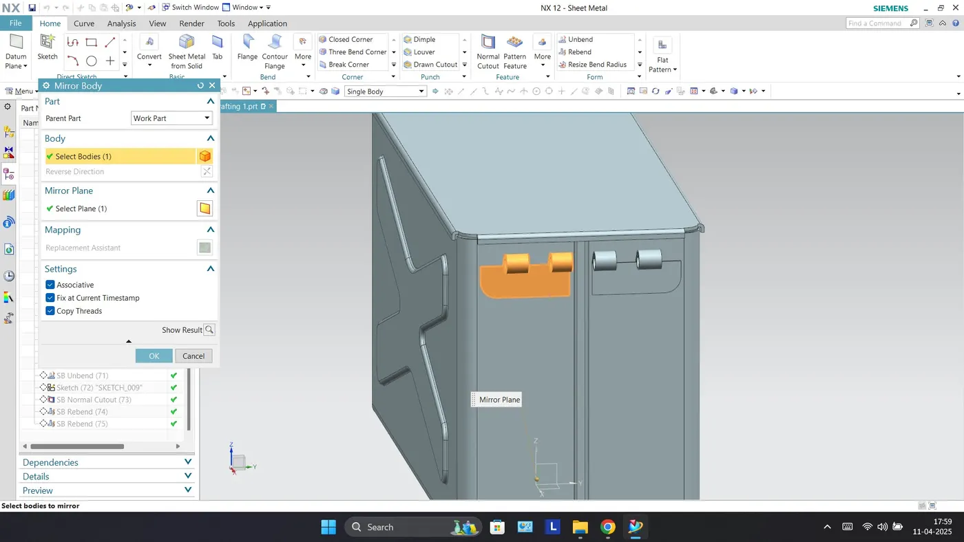
Mirror Body - This feature is used to copy features across planes.
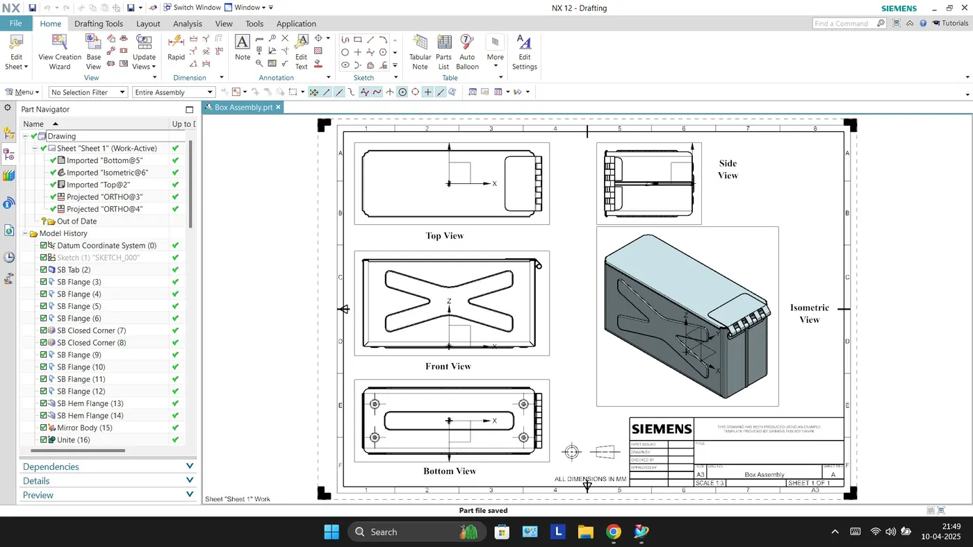
Drafting - It is possible to create a 2D drawing from a 3D model using the NX Drafting application. With the 3D model opened in NX, go to application than Drafting, this disables the sheet metal application and starts the drafting application.
Conclusion
By designing this casing, we have understood and learnt different tools such as Tab, Flange, Hem Flange, Bead, Dimple, Unbending, Rebending and Normal Cutout on Siemens NX CAD. The dimensions as provided were followed during the designing of Box Assembly on software.
Flow Chart
Tab
Flange
Closed Corners
Flanges
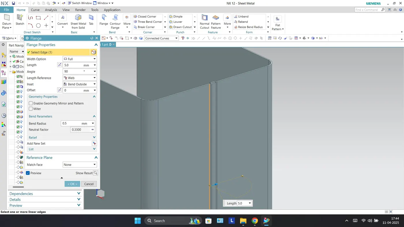
Hem Flanges
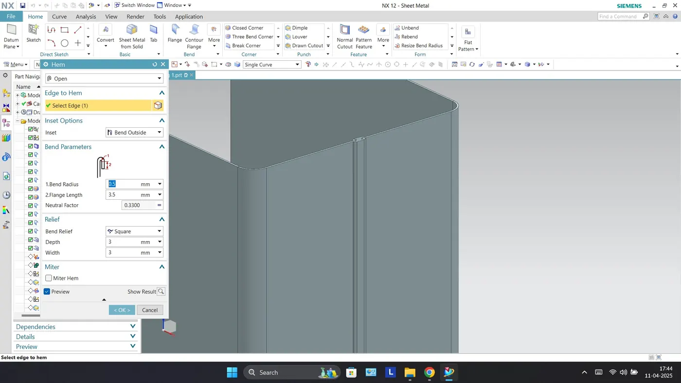
Mirror Body
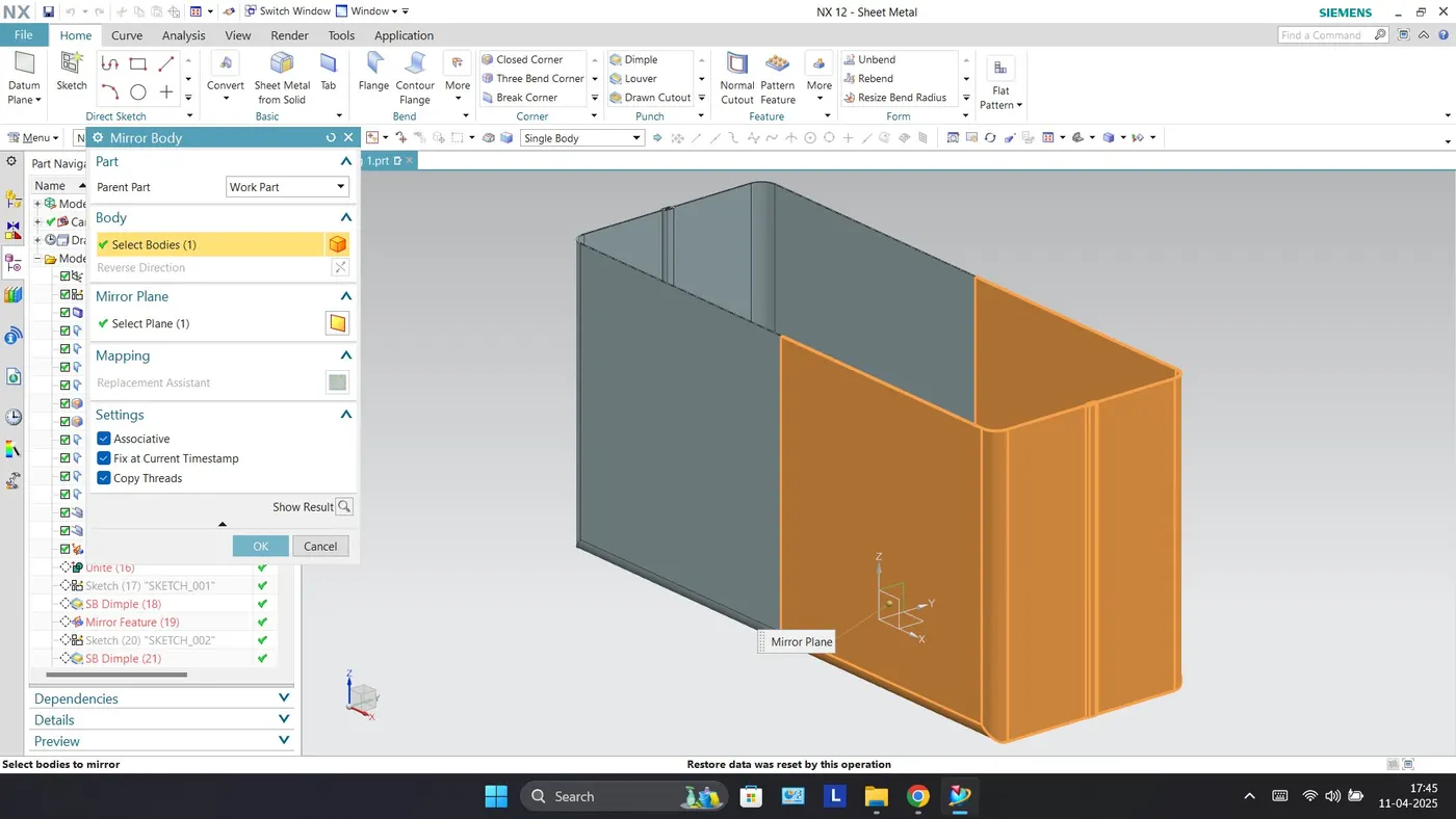
Unite
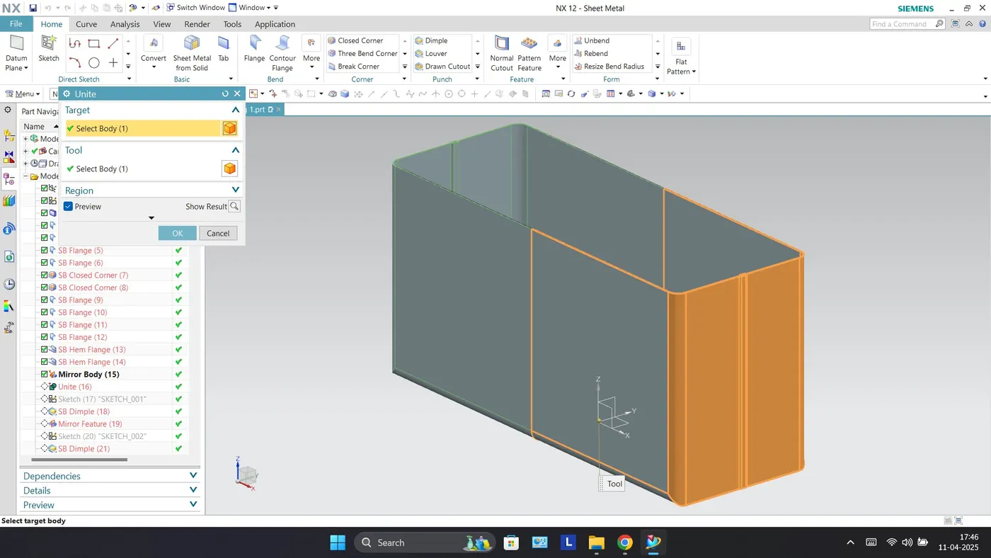
Dimple
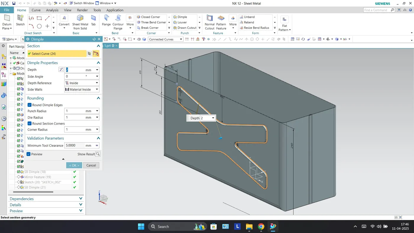
Base Dimple
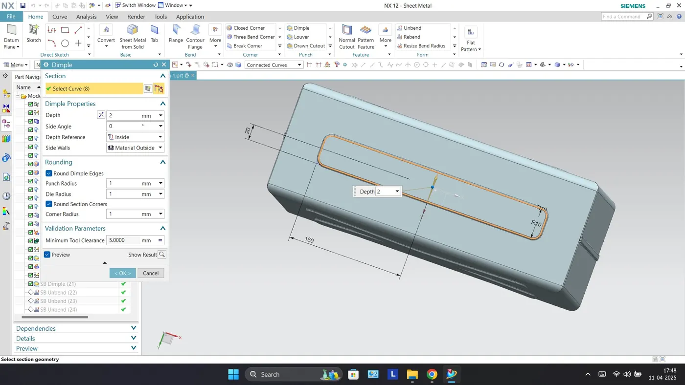
Unbend
Rebend
Bead
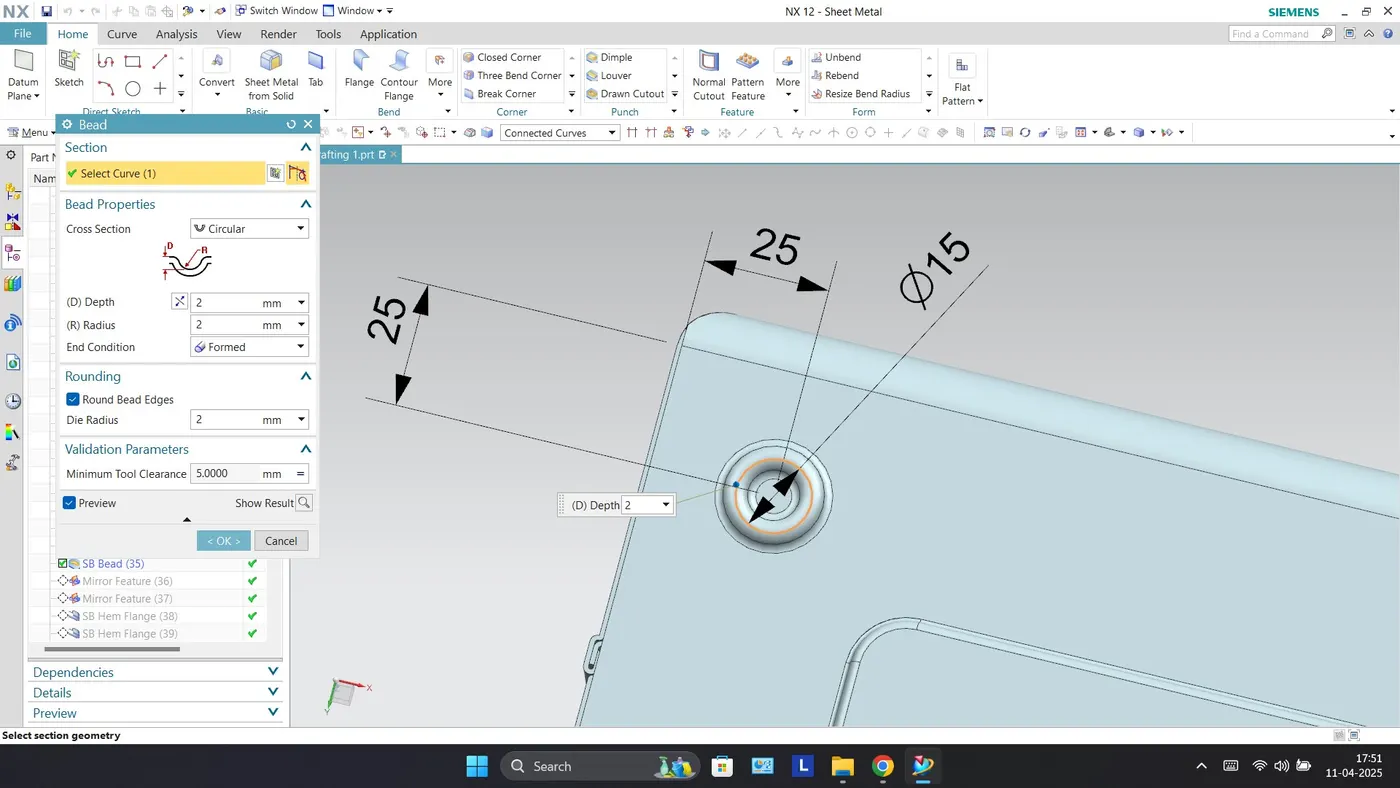
Hem Flanges
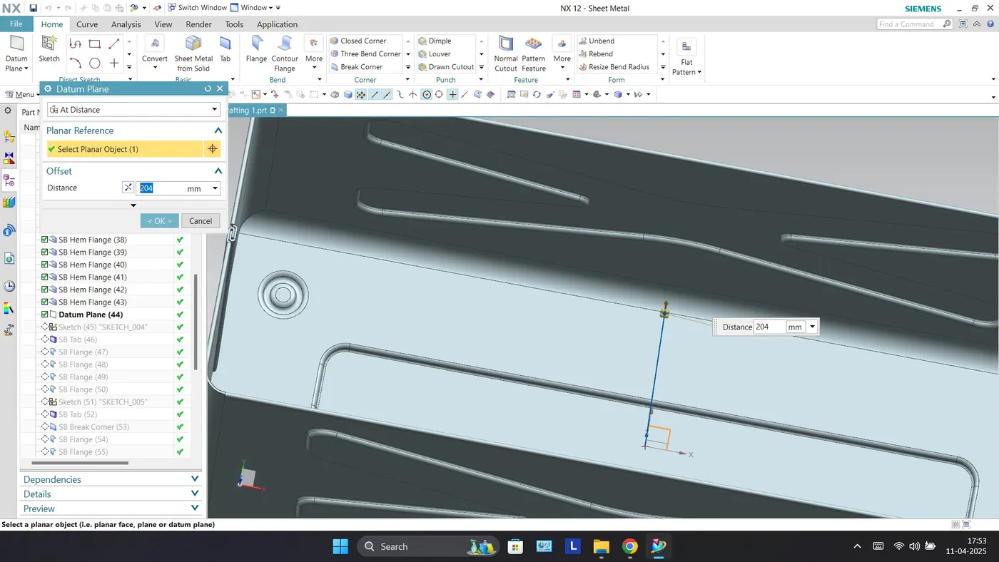
Datum Plane
Tab
Flanges
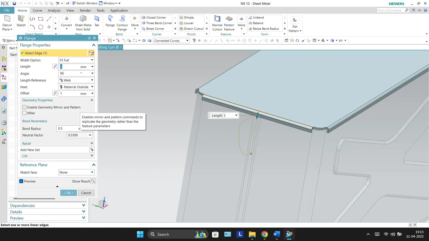
Tab
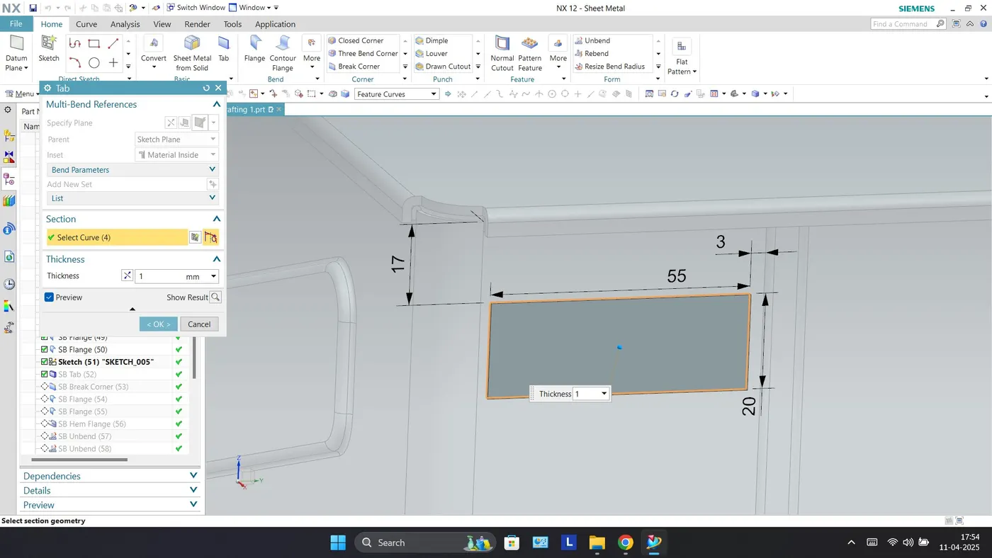
Break Corner
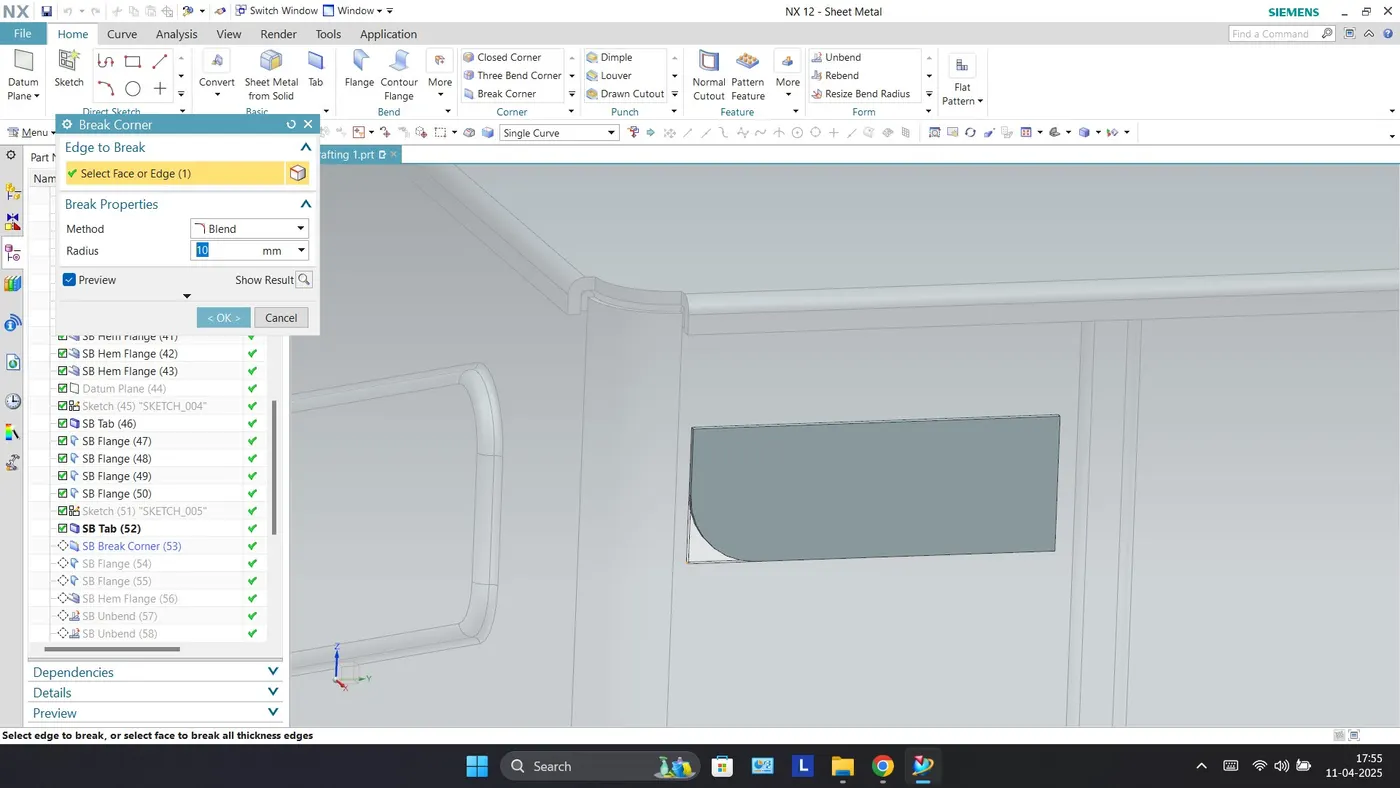
Flange
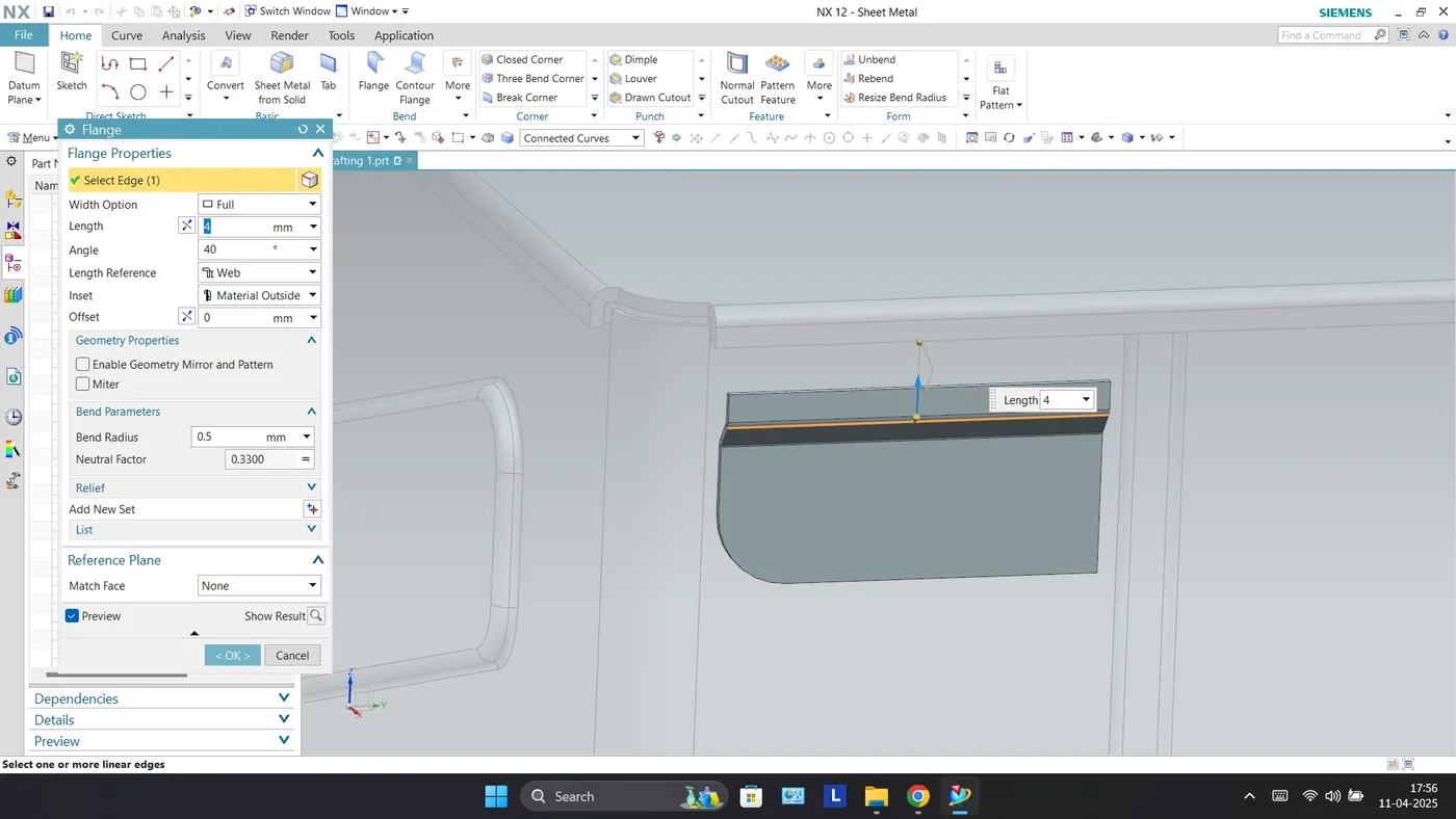
Hem Flange
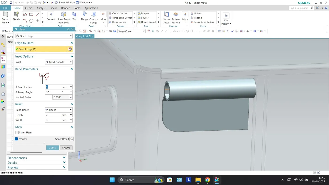
Unbend
Normal Cutout
Rebend
Mirror Body
Tab
Break Corner
Flange
Hem Flange
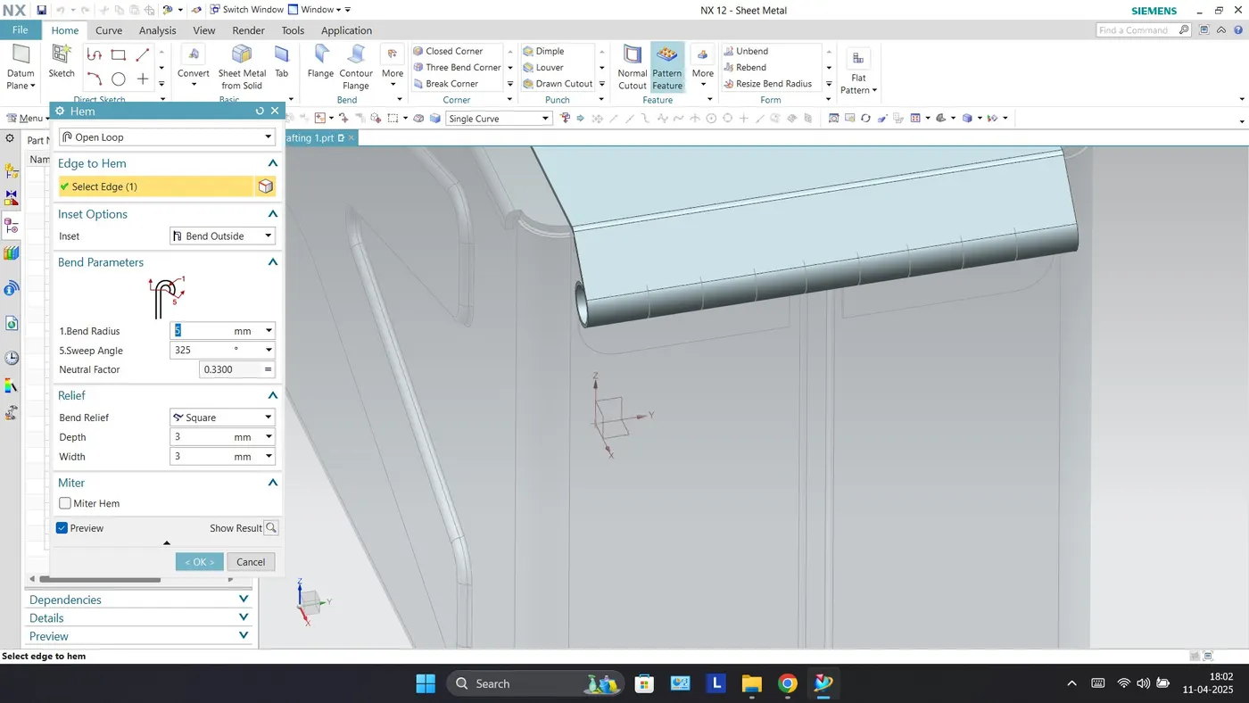
Unbend
Normal Cutout
Rebend
Isometric View
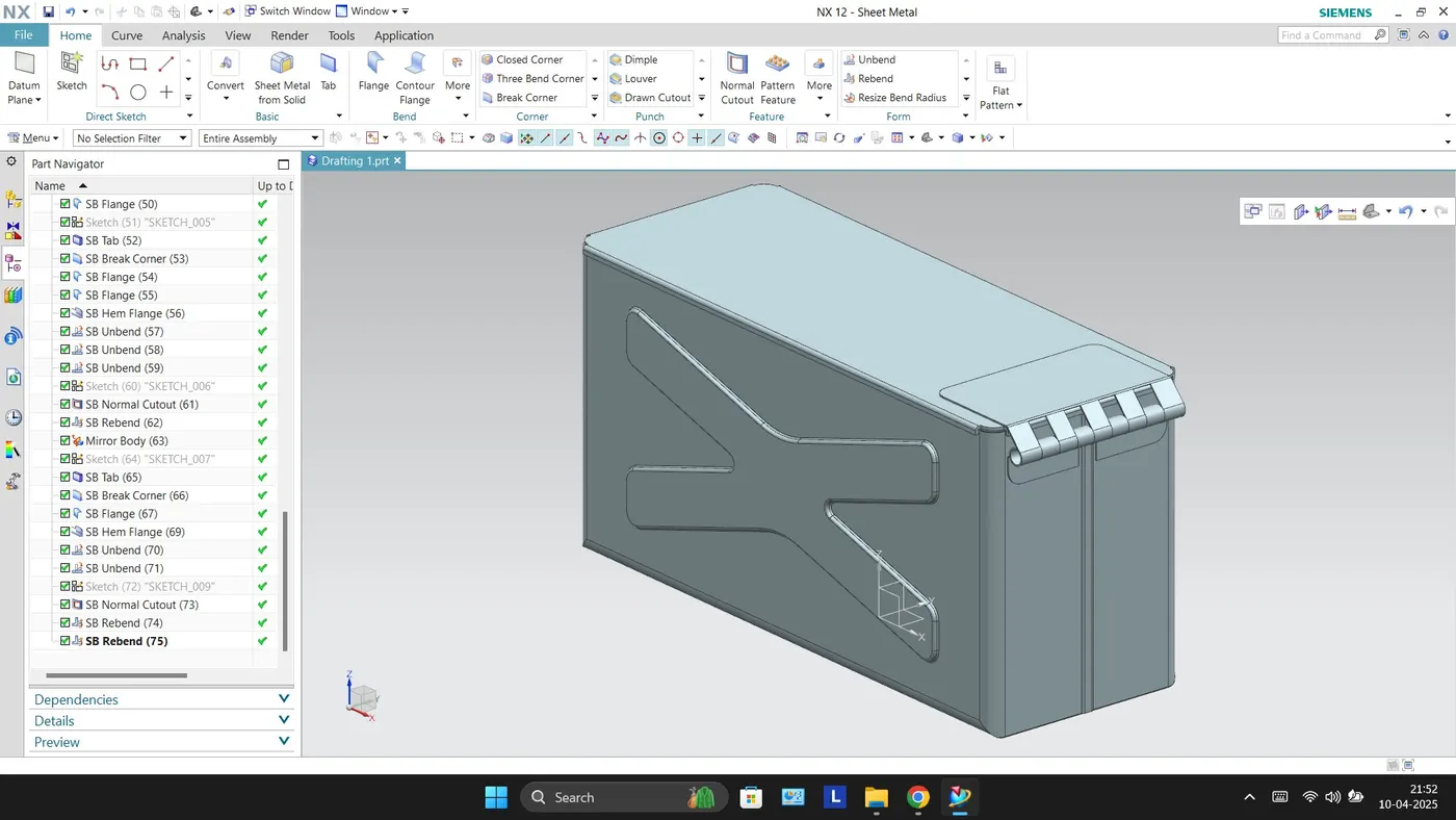
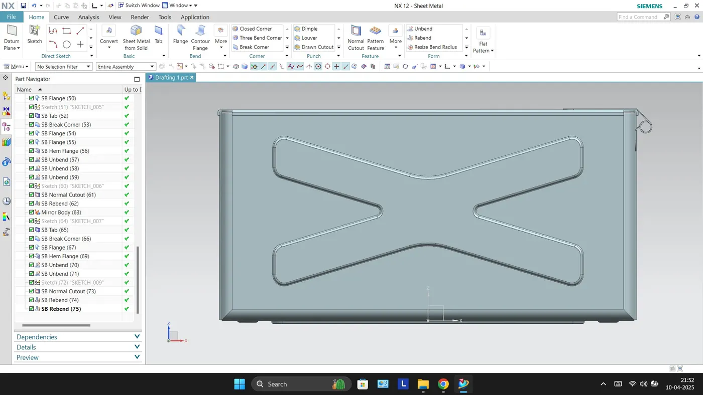
Front View
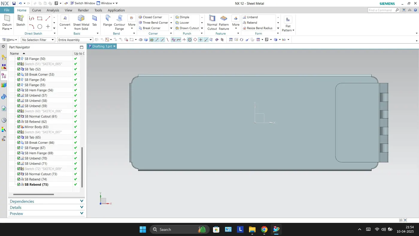
Top View
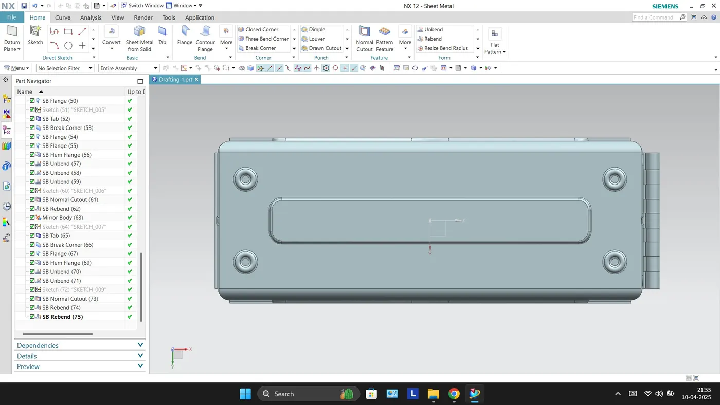
Bottom View
Right Side View
Drawing Sheet