Advanced Sheet Metal Design Using NX Cad Challenge_7_ Metal bracket-II
Project: Advanced Sheet Metal Design Using NX Cad Challenge_7_ Metal bracket-II.
Introduction
Sheet Metal is metal formed by an industrial process into thin, flat pieces and it can be cut and bent into a variety of shapes. Sheetmetal is a comprehensive cold working process for metal sheets usually below 6mm, including shearing, punching/ cutting/ folding, riveting, splicing, etc.
In the Sheet Metal application, we can create uniform thickness sheet metal parts using basic features such as flanges, tabs, and jags. We can also do close corners, cutout, and stiffening features.
This project is to create the Metal Bracket, by creating the solid model and wrapping the sheet metal over the solid surface. Then we need to add the features to the wrapped sheet metal. This involves leveraging NX's sheet metal features, such as Counter Flange, Normal Cutout, Break Corner, Unbend, Bead, Rebend, Hole, Advanced Flange and Gusset to create the desired Metal Bracket.
Process
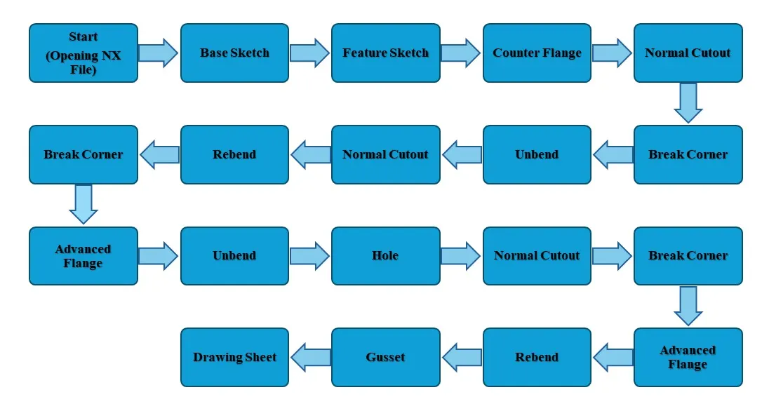
The Sheet Metal Bracket has been designed with the below mentioned flow chart process.
Flow Chart
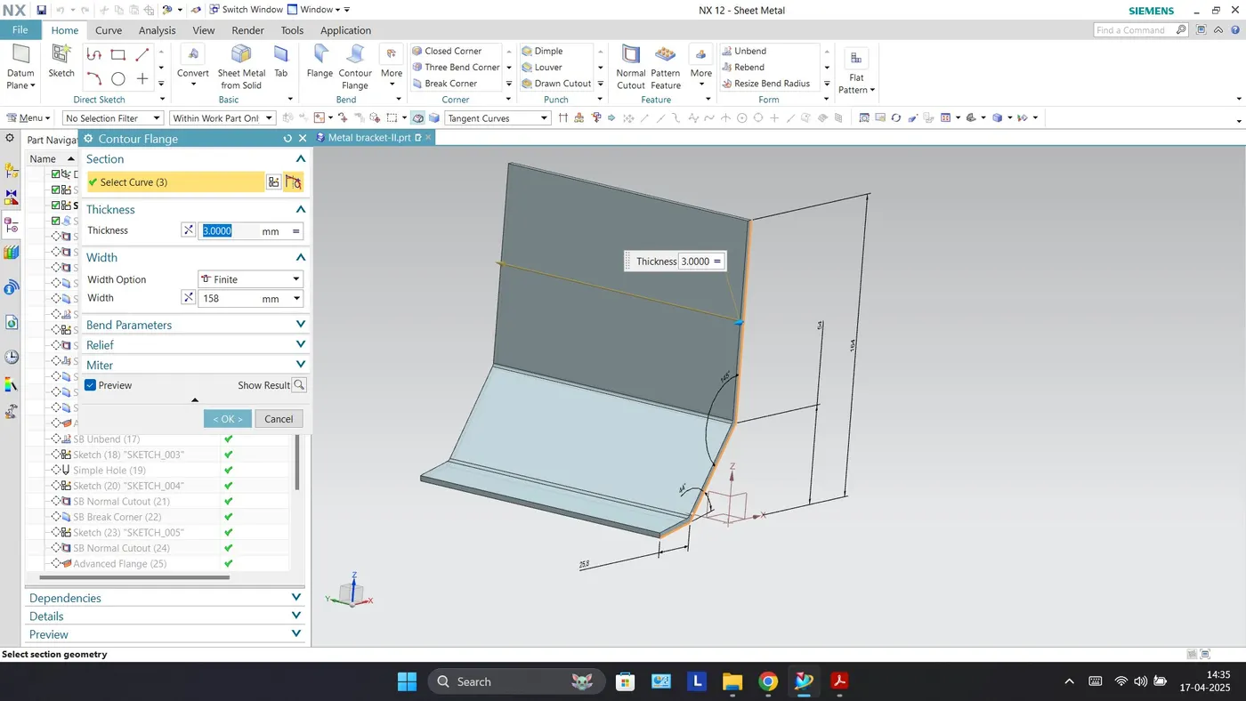
Contour Flange: This command is used to create a base feature by extruding a sketch along a vector or adding material by sweeping a sketch along an edge or a chain of edges. It can be used to create complex bends and shapes in the sheet metal part.
Base Sketch
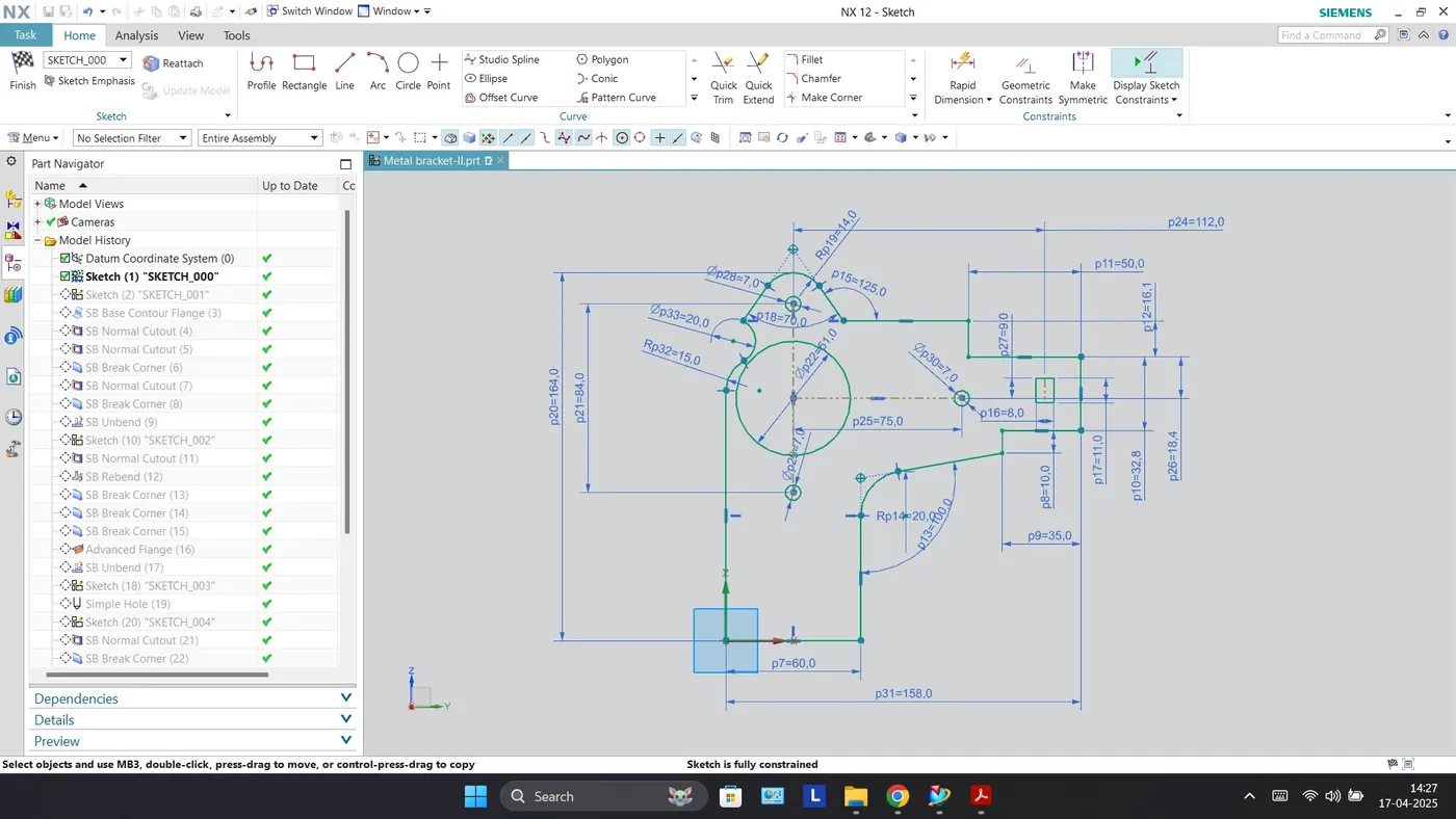
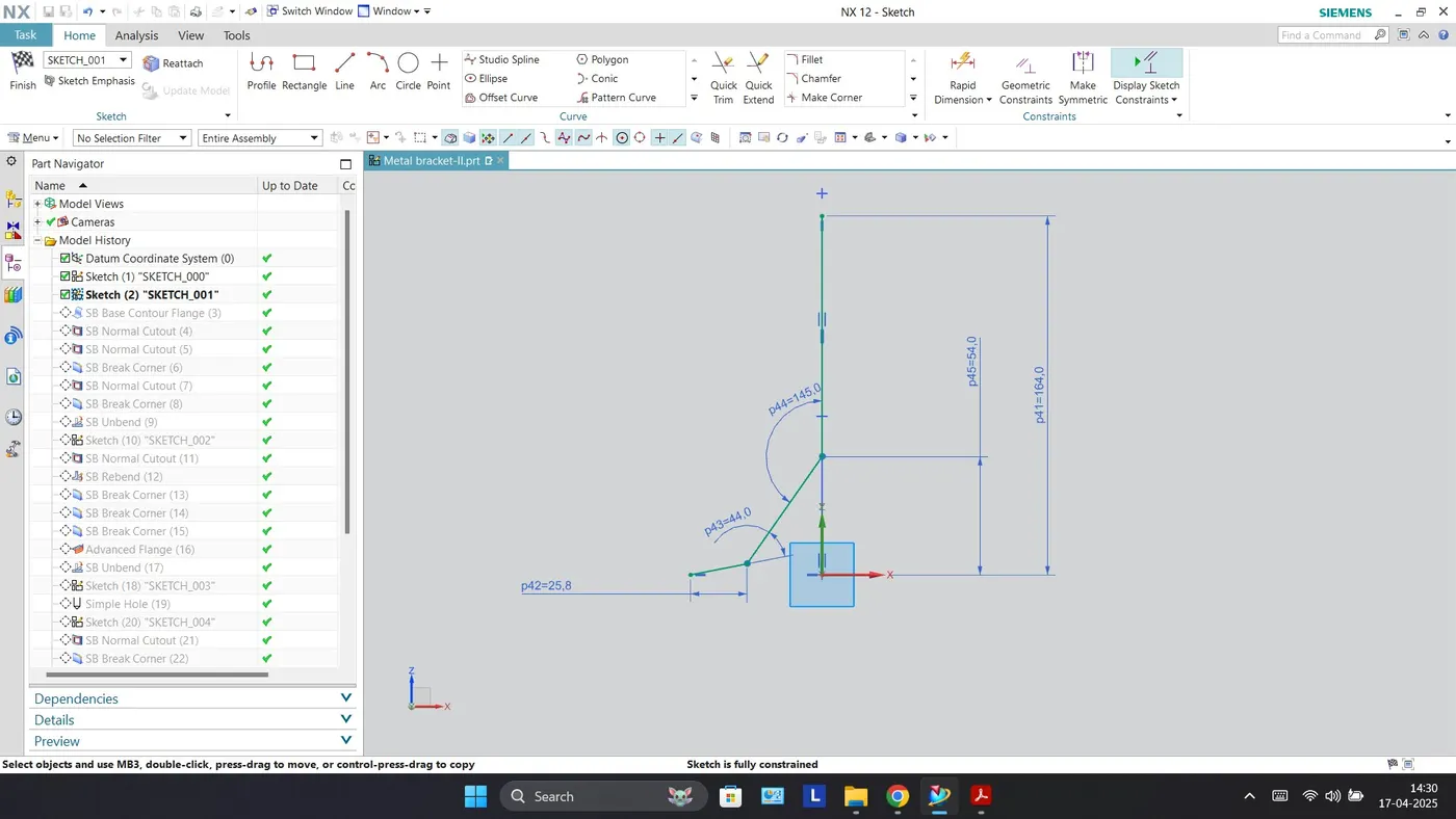
Sketch Feature
Contour Flange
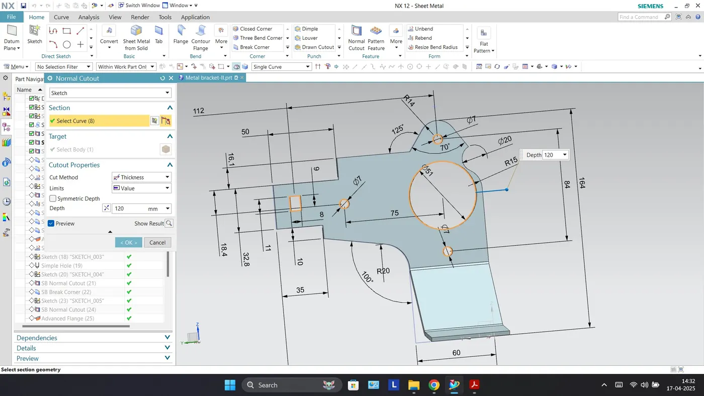
Normal Cutout: The normal cutout feature cuts the material by projecting a sketch onto the model and then cutting perpendicular to the faces intersected by the projection.
Normal Cutout
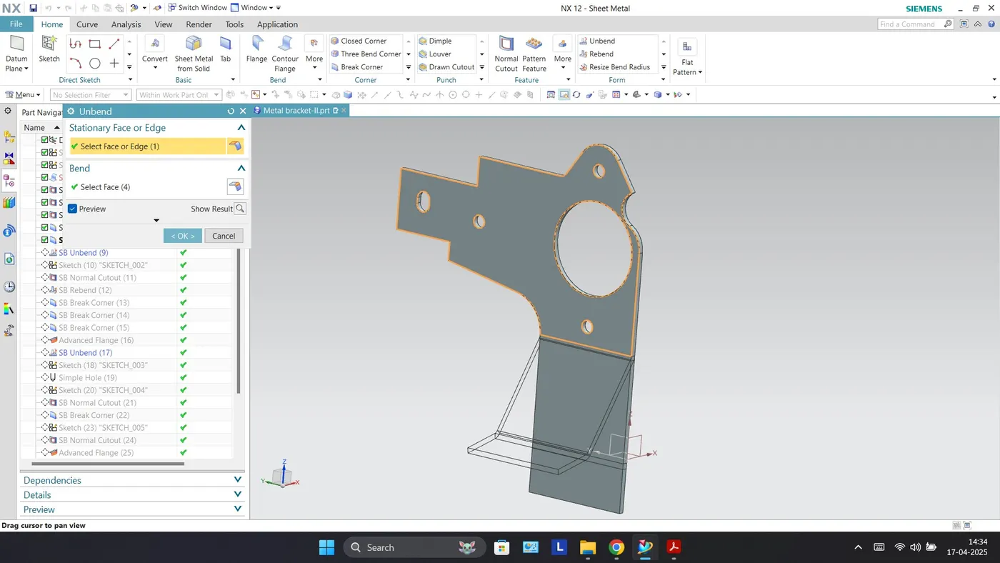
Unbend: This command is used to unbend the sheet metal. The punching operation can be performed only by unbending the sheet metal.
Unbend
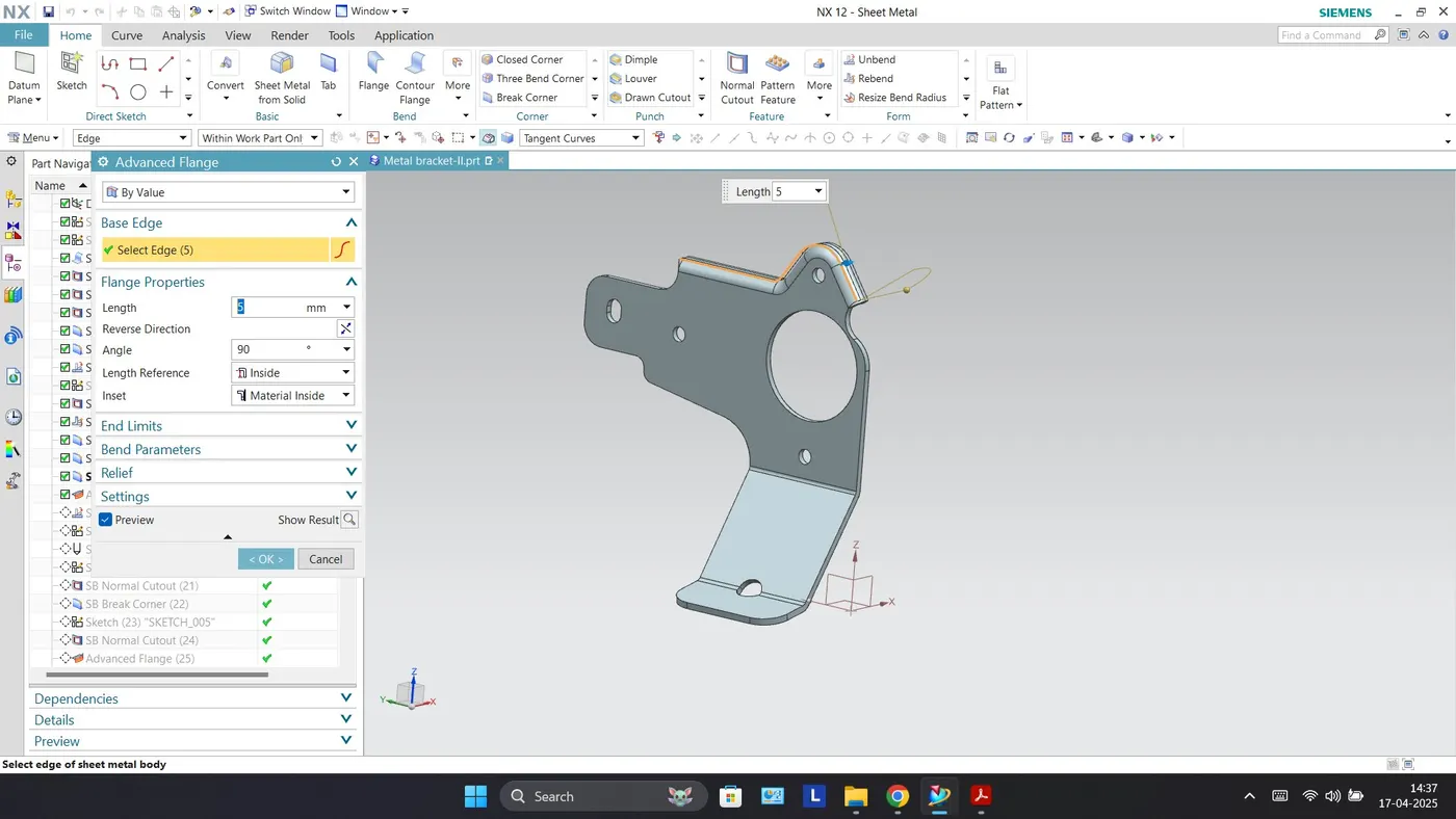
Advanced Flange: This command is used to add flanges along an edge using a bend angle or a reference face.
Advanced Flange
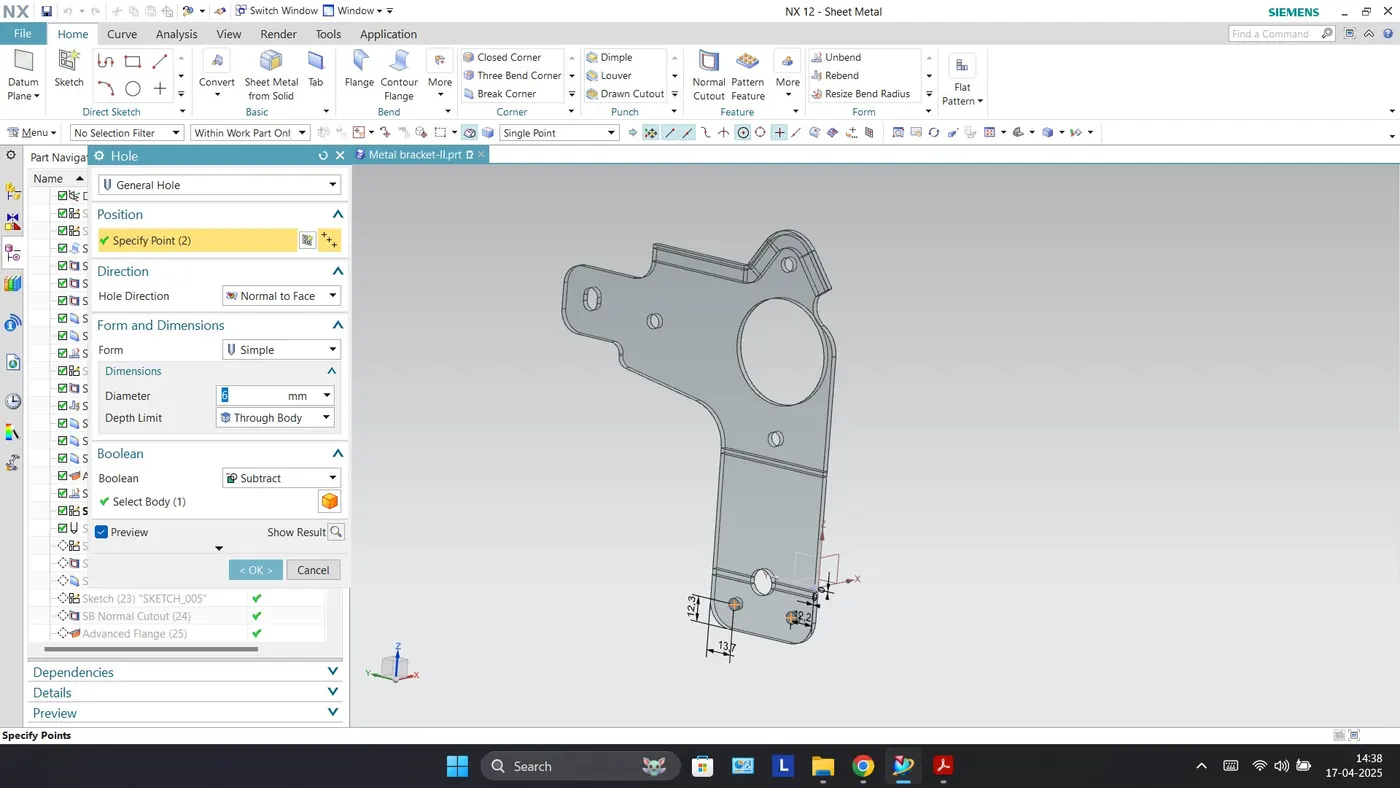
Hole: This feature adds a hole to one or more solid bodies in a part or assembly with options for counterbore, countersink, or threaded.
Hole
Break Corner: It creates Rounds or chamfers in a sharp corner of a tab or a flange.
Break Corner
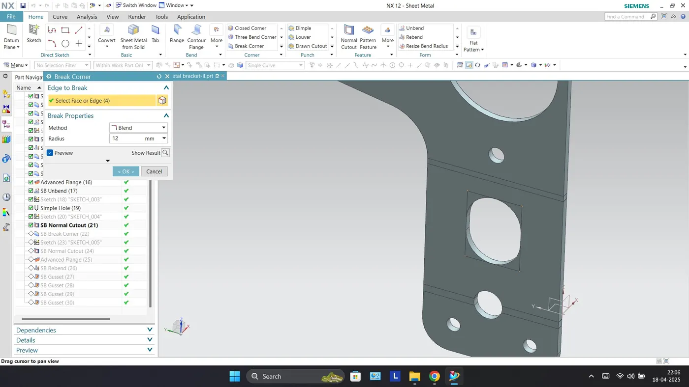
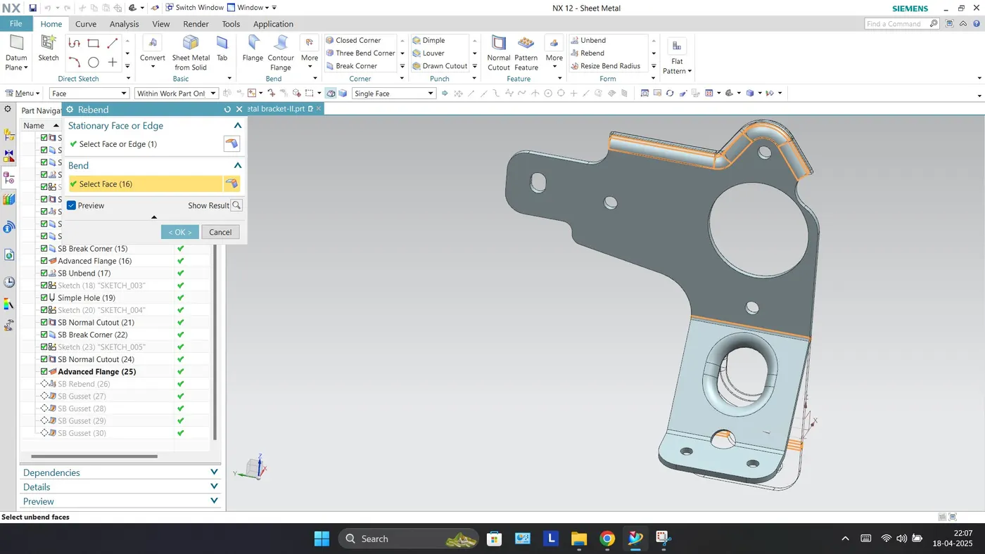
Rebend: Rebend feature is used to get the original bend shape after performing operations like a dimple, bead, etc. It's a tool to get the flanges of the sheet metal body into its original position that flattened with unbend tool to create some some complex structure on the sheet metal body.
Rebend
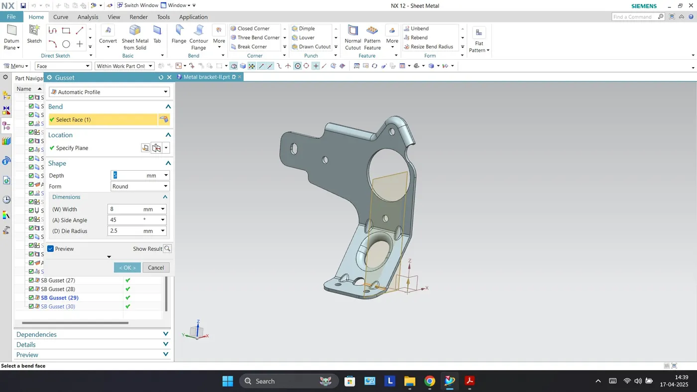
Gusset: This command is used to create stiffening gussets on the part.
Gusset
Drafting: It is possible to create a 2D drawing from a 3D model using the NX Drafting application. With the 3D model opened in NX, go to application than Drafting, this disables the sheet metal application and starts the drafting application.
Drawing Sheet
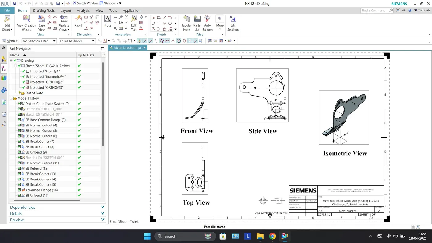
Isometric View
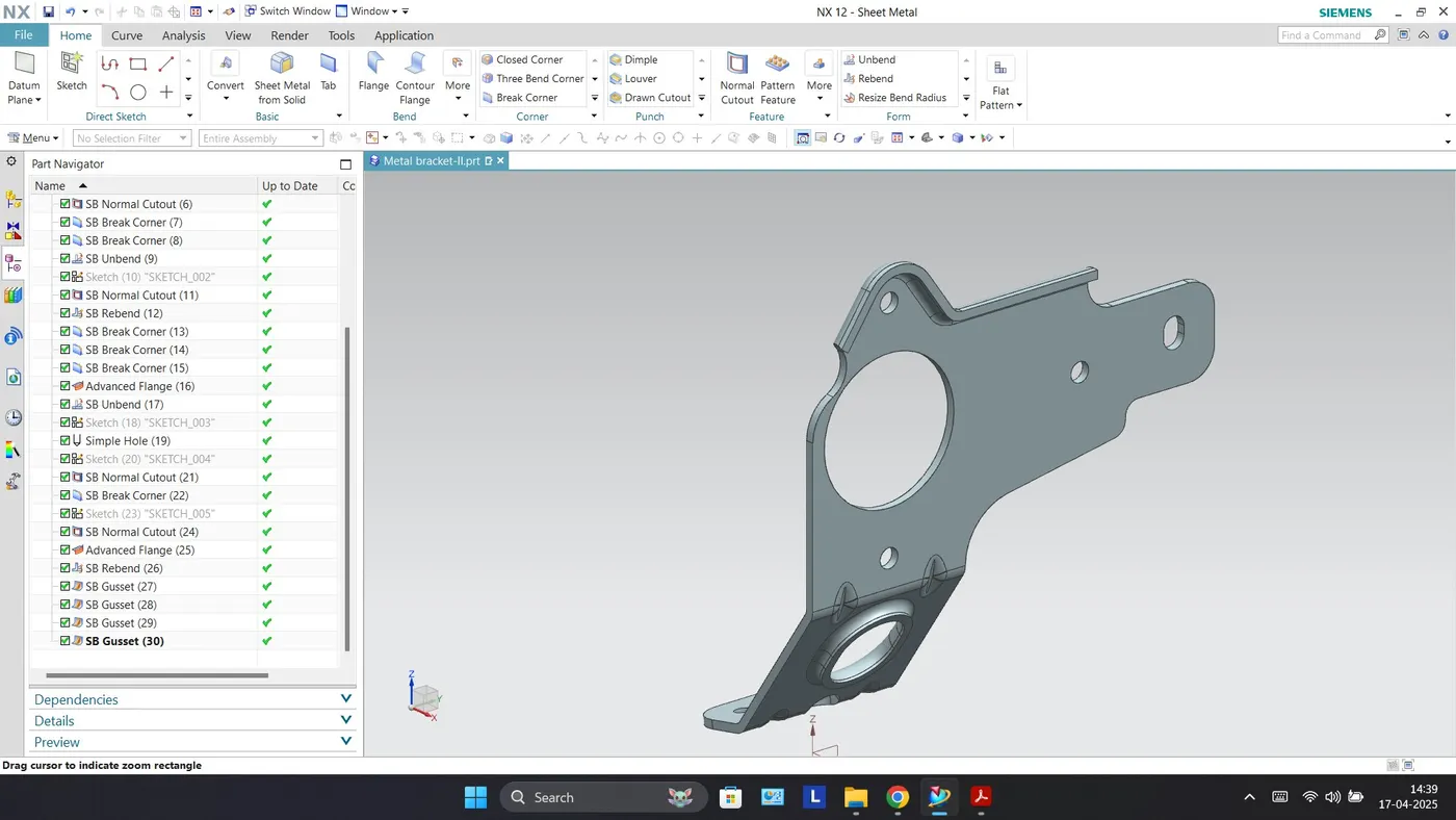
Front View
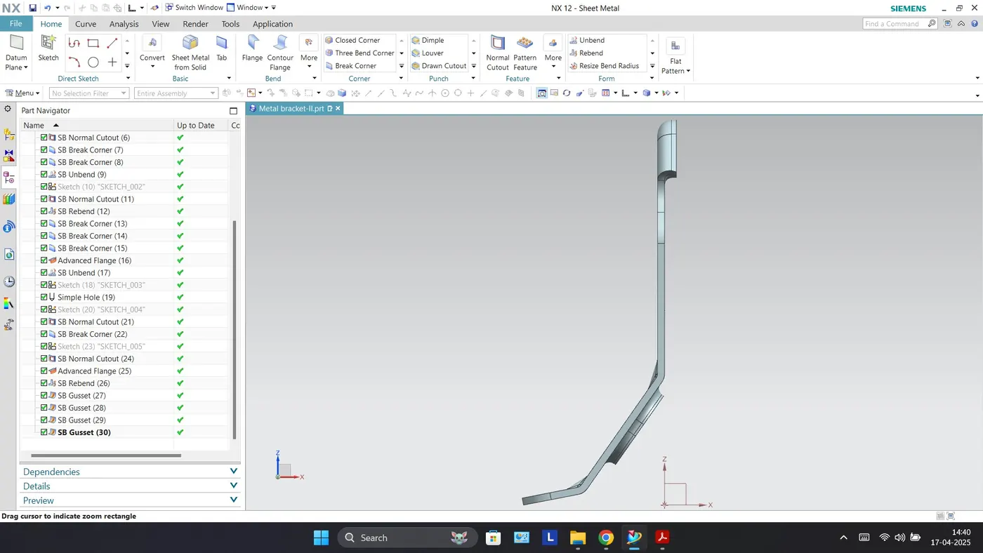
Top View
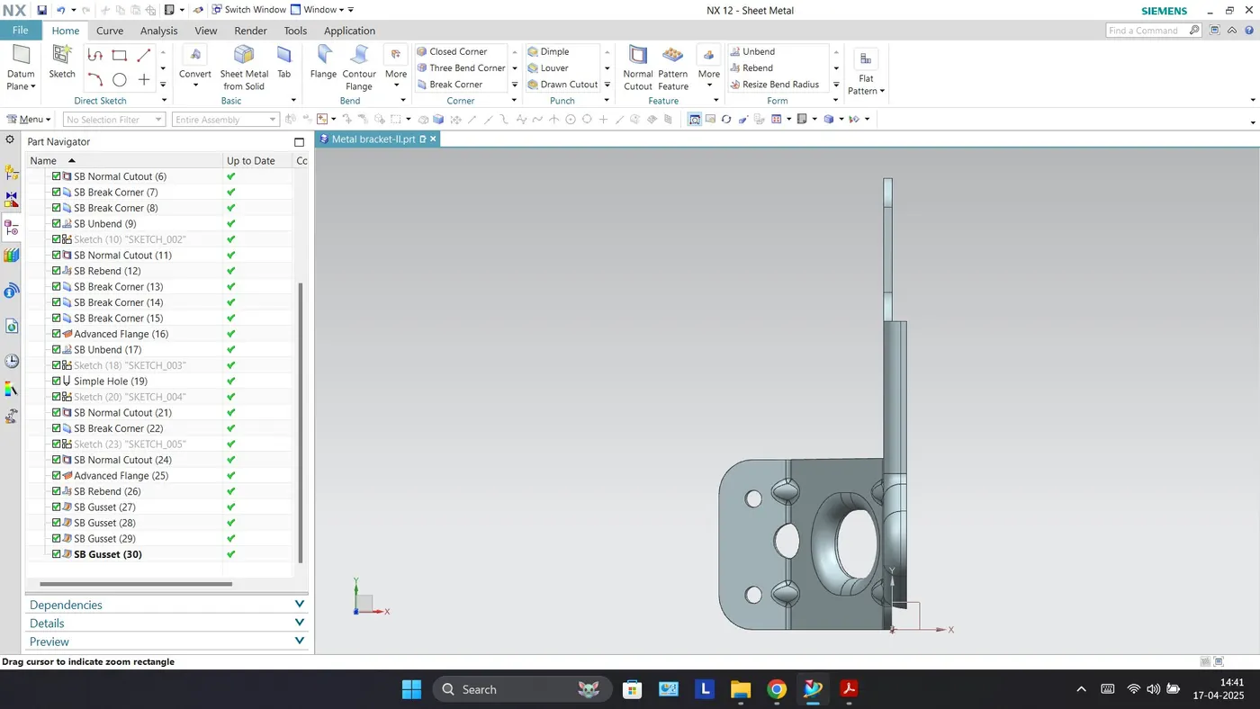
Side View
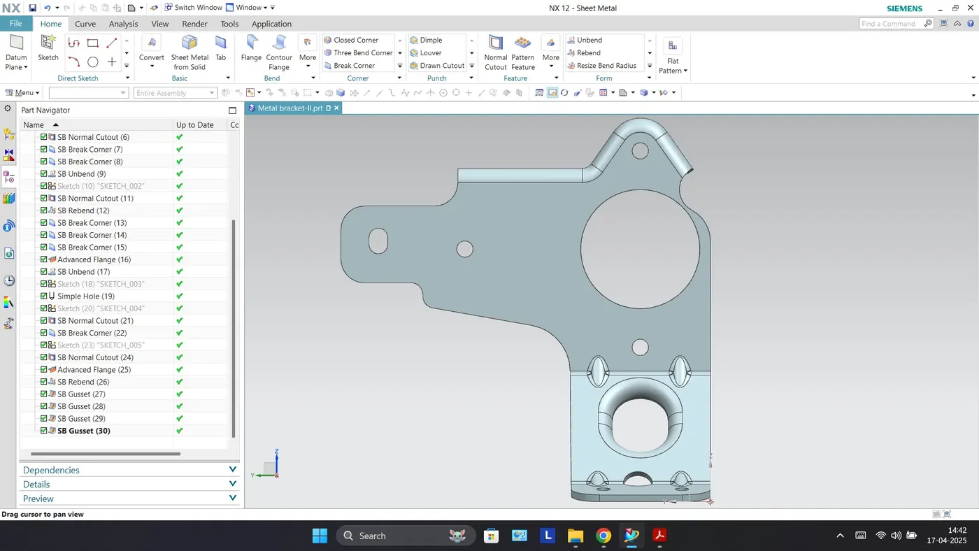
Conclusion
By designing this Metal Bracket, we have understood and learnt different tools such as Counter Flange, Normal Cutout, Break Corner, Unbend, Bead, Rebend, Hole, Advanced Flange and Gusset on Siemens NX CAD. The dimensions as provided were followed during the designing of Metal Bracket on software.