Project
REPORT ON CONTINOUSLY VARIABLE TRANSMISSION (CVT) BAJA ALL TERRAIN VEHICLE (ATV)
INTRODUCTION
An ATV is an All Terrain Vehicle, ATV is a vehicle that travels on low-pressure tires, with a seat that is straddled by the operator, along with handlebars for steering control. As the name implies, it is designed to handle a wider variety of terrain than most other vehicles. In this project the Model of Bajaj ATV is studied knowing all the components and system used in the model. In this two types of system is considered open loopa nd closed loop (with lookup table), both he system is analysed and compared.
AIM
- Discuss about the components of BAJA ATV
- Vehicle modelling a) Defining gear ratio b)Effects of parameter variation
- Incorporating CVT data into the model
BAJA ATV
BAJA ATV is a all terrain vehicle which is able to
- climb any hills and dips
- travel in any road condition off road and on road
- travel in any weather condition
The BAJA ATV model in matlab is build to study the different parameter conditions during different modes like throttle response, weight change, etc.
There is no limit for ATV. The ATV consists of following components or parts
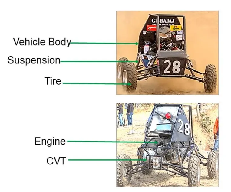
a) Vehicle body
Vehicle body consist of all the mass, the forces like air drag, hill climb depends and acceleration depends upon the mass of the body. Vehicle body must sufficient to hold all the components and pay load wieghts, and also rigid to support any crash.
Several terrain inputs are given to the system like inlination, wind speed, velocity etc.
b) Tires
The tire must have high tread and enough adhesive friction in all terrain conditions, as the vehicle is also an off road vehicle
c) Suspension
Suspension is a main component of ATV as the are needed to act in more in off road condition, usually spring based suspension system is used in ATV.
d) Engine
The engine must be capable of supporting the neccesary throttle response and should give enough power to the vehicle during different terrain conditions. In this model a generic engine is considered.
e) CVT
A CVT (Continuously Variable Transmission) is an automated transmission that can change gear ratios smoothly across a wide range. Other transmissions, on the other hand, offer a restricted number of fixed-step gear ratios. A CVT with appropriate control may allow the engine to run at a constant RPM as the vehicle drives at different speeds.
MODELLING
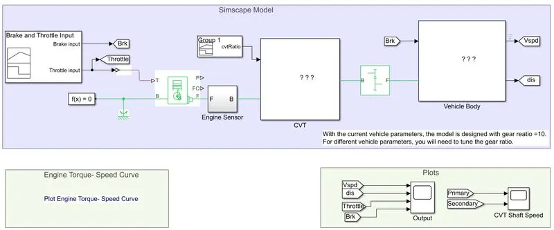
The Bajaj ATV includes a engine, control inputs like acceleration and brake, the transmission part, tires and body parts. The ATV modelling in Simulink considers all the parts of the ATV. The MATLAB SImulink model of the ATV is shown below
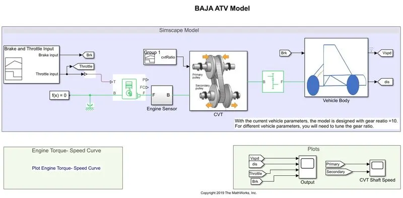
The modelling part includes
- Driver input data
- Generic Engine
- CVT
- Fixed gear
- Vehicle Body
Driver Input Data:
The driver input data consist of how the acceleration and brake command are given into the system. The driving input given in this case is by a Signal builder block, the input acceleration adn brake signal are as follows
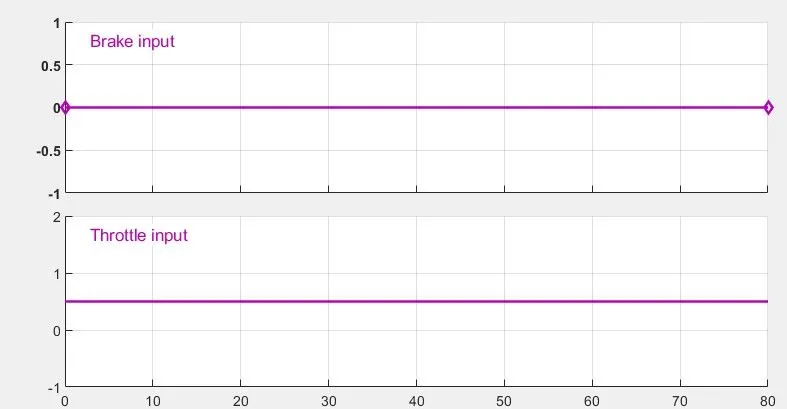
The input is a WOT (Wide open Throttle) with a amplitude of 0.5 throttle input and no brake signals are applied.
The throttle input is given to the Engine and Brake output is given to the tires.
Generic Engine:
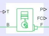
Generic engine is mechanical engine, it works based in the input throttle command. The mechanical rotational output is transferred to the CVT transmission system.
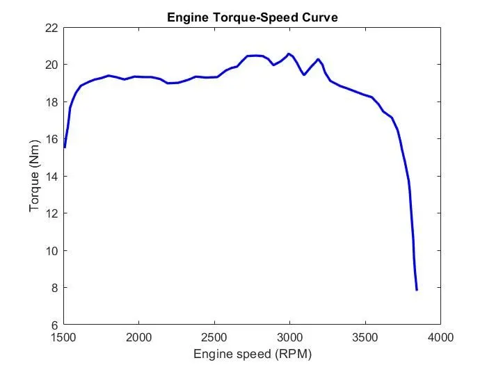
The Engine Torque-Speed chara is shown below
CVT:
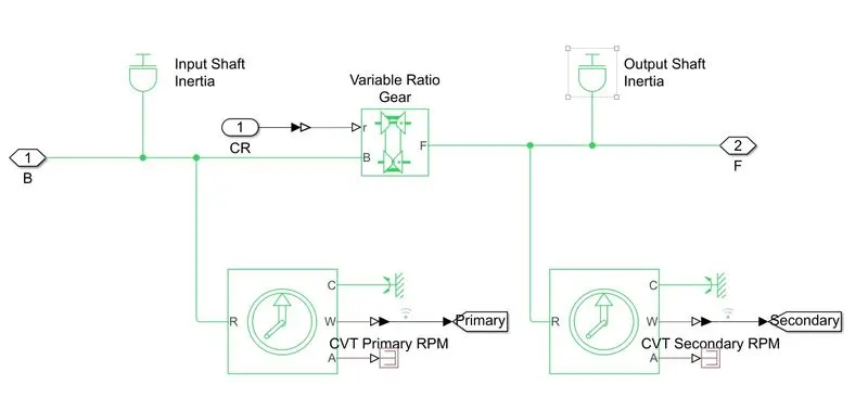
The CVT is a continous variable transmission consist of two rotating gears connected by a belt. The CVT model is give below with two shaft and variable gera ration which act as the CVT.
CVT Ratio (For open Loop Model Only):
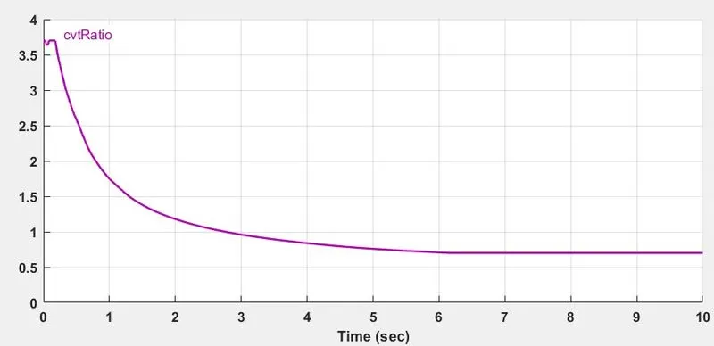
The CVT ratio is given input to the CVT for controlling the ratio of the primary and secondary in the open loop model, this is given through a signal builder as shown below, at starting the ratio is high and then exponetially decrease to 0.4. Thus at starting it will have high torque and low speed and at end low torque and high speed.
Fixed Gear:
Fixed gear system is to further match the RPM of the secondary shaft with the tire.

Vehicle Body:
The vehicle body inludes all the physical parts of the vehcile except the power train part. The Vehicle body includes details of the
- Mass of the body
- Mass of the payload
- Tire rolling friction, radius, braking, etc.
- Body coefficient of air drag
- Environmental details like
- Road inclination
- Road conditions
- Wind speed
- Air density
The model of the vehicle body is as given below
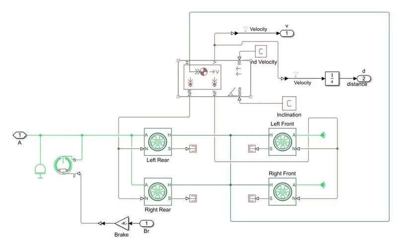
The components used in this model are
- Double-Shoe Brake: This brake system is combined with the tire shaft, during brake input it retards the rotation of the shaft.
- Tire (Magic formula): This is a tire model in this model there 4 tire and hence 4 blocks, the input details of this block consist of the tire radius, coefficient of rolling friction, load acting on the tire, etc.
- Vehicle body: The vehicle body gathers all the details of the physical part of the body as the wind and road inclination effects the body they are also consider as the input to the block. The block consist of details like vehciel mass, payload mass, vehicle physical details, air drag, etc.
- Shaft inertia
SIMULATION
Cas1: Open Loop System
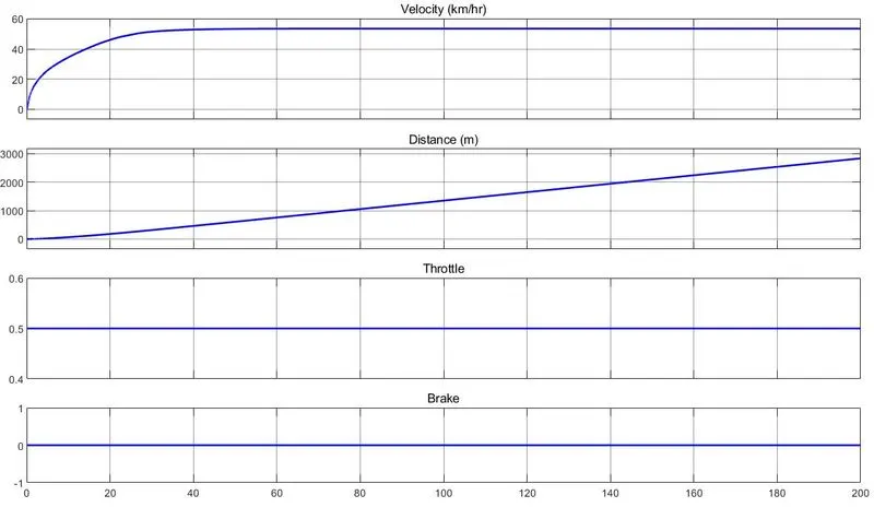
The simulation of the model is done for analysing the working of ATV, with following input
Simulation time: 200s
Test detail: WOT test
Brake input: 0
Throtle input: 0.5 at 0s
The output: velocity and distance; input: throttle and brake observed as
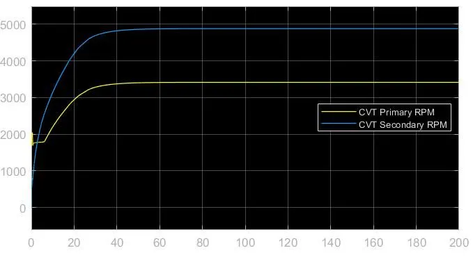
The CVT primary and secondary RPM as
OBSERVATION:
- At initial the primary shaft starts to rotate. The rise of the primary and secondary RPM to its required RPM is slow due to the inertia of the shaft and the body.
- The CVT ratio decreases gradually and the secondary shaft overtakes the primary shaft RPM when it falls below 1.
- At initail the vehicle requires high torque to start from rest, during this time the ratio is high so the torque at end of econdary shaft is high.
- The CVT ratio is prefed and the CVT ratio is independent of the vehicle ovement in open loop system. So the efficiency of the CVT is decreased.
- The primary shaft works at critical stable region with a RPM of nearly 3500, so system may fall under unstable condition.
CASE 2: Closed Loop System with lookup table
In this the CVT ratio block is replaced by the input "Velocity" from the vehicle body.
The system model is as given below
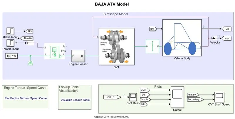
The CVT subsytem consist of a lookup table, with respect to the speed the lookup table points the CVT ratio and gives input to the CVT.
The Lookup table shown below
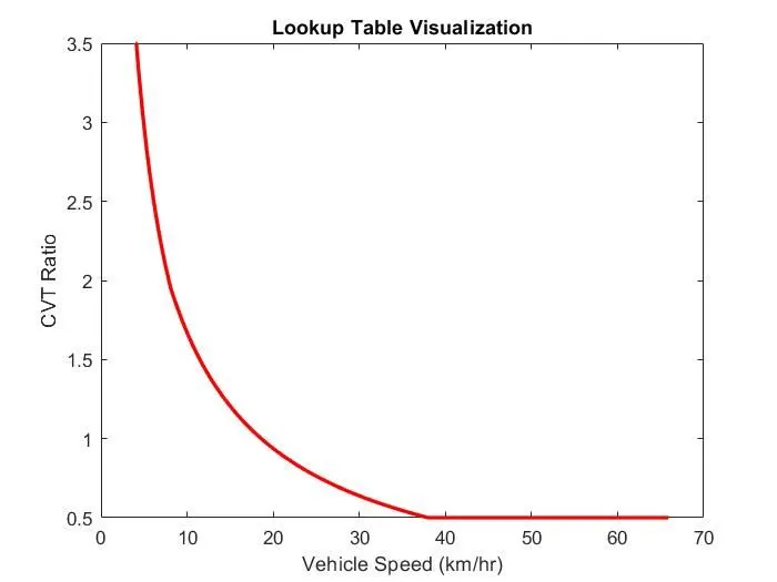
From the lookup table, from the speed range of 0-5kmph the CVT ratio is 3.5 and above 5kmph to 37kmph the CVT ratio falls upto 0.5, afterwardsthe CVT ratio becomes constant for the speed grater than 37kmph.
The Engine Torque-Speed chara is same as that of the open loop system, so all the parameters are considered same as that of the open loop system.
Consider the same test case as that of the open loop system.
Simulation time: 200s
Test type: WOT
Brake input: 0
Throttle input: 0.5 at 0s.
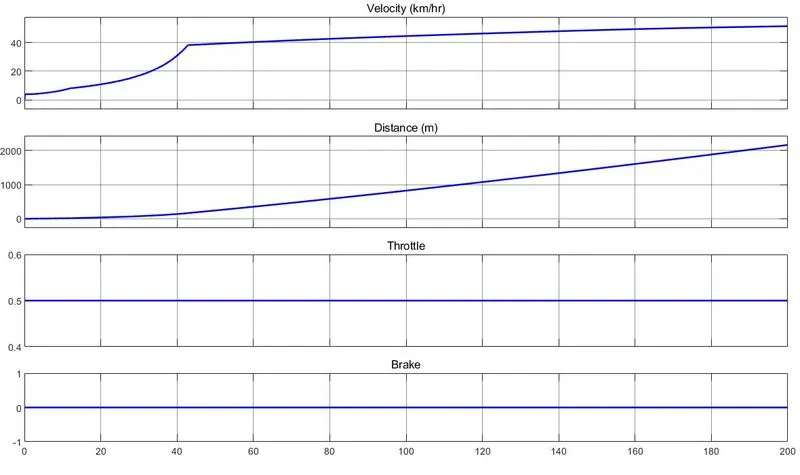
The output: velocity and distance; input: throttle and brake observed as
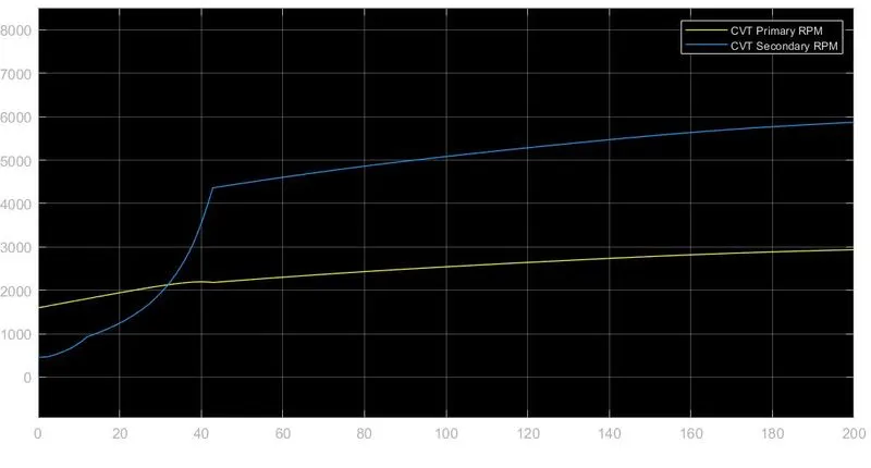
The CVT primary and secondary RPM as
OBSERVATION:
- The Speed of the vehicle rises exponentially from 0 to 37kmph, and later it rises slowly. This is due to having CVT ratio fixed to 0.5 afterwards.
- The primary shaft RPM doesn't vary much and rises gradually, so the maximum efficient tracking of the engine is made. Also the RPM is between 200 to 3000, which is in the stable region.
- The secondary shaft RPM varys according t the CVT ratio which is based on the velocity input.
- So the closed loop system is stable
- The CVT minimum ratio is kept to 0.5 in this which helps in keeping the engine reliable.
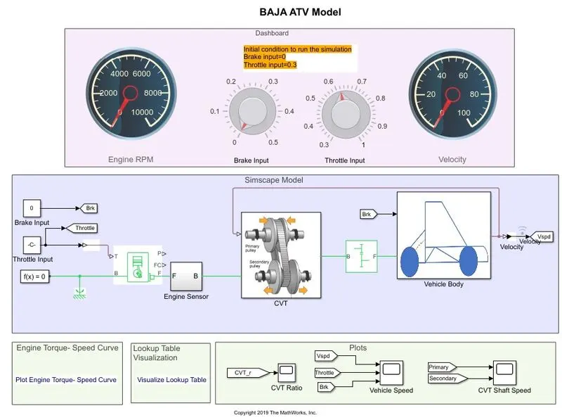
The model also incorportae Dashboard to analyse the working of speed and RPM of the engine in real time operation, by adjusting the brake and throttle input. The model is shown below
CONCLUSION
- Discussed about the Bajaj ATV MATLAB Model and its components used in modelling.
- Discussed the working of both Open loop and Closed loop model.
- In open loop no feedback of the vehicle is considered and the CVT ratio varies with respect to time without any aware of the vehicle working.
- In closed loop vehicle velocity is considered in determining the CVT ratio, the CVT ratio is changed with respect to Speed based on the look up data given.
- The engine working is not reliable and safe in pen loop, while safety and reliability of the engine is considered in closed loop system.