Week-6 Challenge: EV Drivetrain
1. Converters used in EV/HEV
Consider a series HEV powertrain. In this different types of converters can be seen.
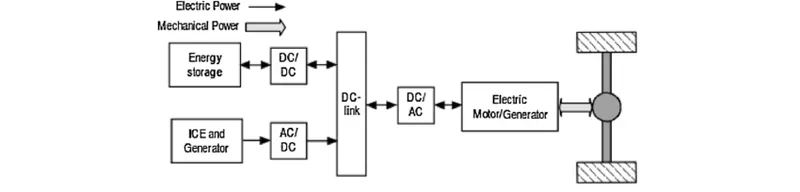
Based on flow of conversion we can classify the converters into unidirectional and bidirectional converters. In that classification we can again classify converters based on the form or level conversion.
A. Unidirectional converters
These converters converts power in one direction only.
a) AC-DC Converter (Rectifier)
This converter converts the electric energy in AC (alternating) quantity to DC (direct) quantity.
Applications: This converter mainly used in powertrain is in on-board charger. When during charging from AC source this on-board rectifier converts the power in AC form to DC form. This power conduction is in one direction unless V2G (Vehicle to Grid) is not implemented.
Different rectifier configurations:
Uncontrolled Rectifier (Half Wave Rectifier, Full Wave rectifier and Bridge Rectifier : Uses diodes)
Controlled rectifier (Half Wave Rectifier, Full Wave rectifier and Bridge Rectifier : Uses controlled powersemiconductor switches and diodes)
b) DC-AC Converters (Inverter)
These converters are used to convert power in DC form to AC form (mostly Sinusoidal form).
Applications: The unidirectional DC-AC converters are mainly used in powering the accessories in a EV/HEV like Air Conditioning, Lighting, Speakers, etc. Unidirectional DC-AC converters are used to aid AC motors in a EV/HEV where regenerative power saving is not taken.
Different inverter configurations:
Based on source: CSI (Current Source Inverter) and VSI (Voltage Source Inverter)
Based on load : 1-phase, 3-phase or multi-phase.
Based on modulation scheme: PWM (Sine, Space Vector, Discontinous, etc)
c) DC-DC Converters (Chopper)
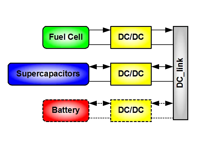
These converters are level converters. The battery and accessories may be at different voltage rating and also the DC bus in EV are taken as high voltage bus. Inorder to change the voltage level of DC chopper circuits are used. In the below image, for fuel cell it uses unidirectional DC-DC converter and for some accessories also as there is no requirement of tranferring power in both direction.
Different chopper configuration:
Buck (Step-down), Boost (Step-up), Buck-Boost, Cuk, Sepic, etc
B. Bidirectional Converters
a) DC-AC or AC-DC BDC
DC-AC BDC can transfer power from DC to AC and AC to DC, so these converter can convert electrical form in AC and DC also. Based on the source side we name it as DC-AC or AC-DC converter.
Applications: These type of converter are used in aiding motor powering with regenerative condition, so during barking the power generated by the motor can be transfeered to battery or other components. This converter is also used in on-board charger where V2G, V2V and V2X techonology is used.
Different configurations:
Based on load(AC)/source(AC) : 1-phase, 3-phase or multi-phase
Based on bridge arm: 6-pulse, 12-pulse, etc
Based on modulation scheme: PWM (Sine, Space Vector,etc)
Based on controller: PI, PR, PID, etc
b) DC-DC BDC
These converters converts DC power in both direction with different DC voltage/current levels.
Applications: DC-DC BDC converters are used in battery, UC and DC motor. During regenerative or plugged condition the power can be transferred to battery or UC to store the energy, and during motoring condition the power is fed from battery and/or UC to power the motor. The converter is also used in DC motor side to transfer power to charge battery and/or UC during regenerative condition and power the motor during motoring condition.
Different configutations:
Isolated ( No physical connection between source and load, using auto-transformer to convert the level) and Non-isolated (physical connection between source and load).
Non-isolated: Buck and Boost converter, Cuk converter, etc
Isoltaed: Resonant converter
Based on controller: CC (constant current), CV (constant voltage) and CP (constant power)
2. Finding steady state speed of vehicle
Given:
Vbatt = 72V
Vrated = 72V
So the chopper is a step-down chopper.
Ra = 0.5 `Omega`
K`phi` = 0.7 Vs
fsw = 400 Hz
d1 = 70%
Vehicle torque-speed relation: `T_v = 24.7 + (0.0051)omega^2`
Chopper output voltage
`V_o = d1*Vbat`
Vo = 0.7*72 = 50.4 V
Speed torque equation of SEDC motor is:
`omega = frac(V_o)(Kphi) - frac(R_a)(Kphi)T`
Substituting the above values in the speed-torwque equation we get
`omega = frac(50.4)(0.7) - frac(0.05)(0.7)T`
In terms of T we get
`T = 70.56 - 0.98omega`
By comparing the torque-speed equation of motor and vehicle we get
`70.56 - 0.98omega = 24.7 + (0.0051)omega^2`
Solving the equation we get two values of `omega`
`omega_1` = -231.072 rad/s
`omega_2` = 38.91 rad/s
We take positive value, the staedy state speed in rpm, N = 372 rpm.
3. SPEED-TORQUE EQUATION IN SIMULINK
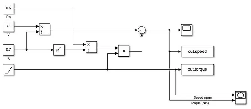
This is a model created in simulink for finding the speed-torque relation of a DC machine.
Speed-torque relation: `omega = frac(V)(Kphi) - frac(R_a)(Kphi)T`
T - ramp input
V = 72 V
Ra = 0.5 ohm
`Kphi`= 0.7 Vs
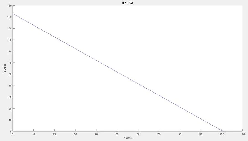
The output of above simulation is
Simulink model: https://drive.google.com/file/d/1tx-vDUI6Zz4hcD6wJstmKhlxm8fvW8W5/view?usp=sharing
4. INDUCTION VS BLDC MOTORS
The Blog written by Wally Ripple on “Induction Versus DC Brushless Motors” describe about positive, negative and application of Induction and BLDC motors in EV/HEV. The main points mentioned in the blog are:
- In present scenario there are different types and configuration of engines, and from these engines one cannot choose the best one as it depends upon the personal requirement like price, performance, etc.
- The technological improvement in EV components is changing yearly, so the EV is becoming more efficient and stable yearly.
- BLDC Motor:
Rotor: Two or more permanent magnets that generate a DC magnetic field
Stator: Houses armature winding
Working: As the rotor rotates the size and polarity of the stator currents must be continuously adjusted and in just the correct way, so that the torque remains constant and the conversion of electrical to mechanical energy is as efficient as possible. An inverter is the device that offers this current regulation. Brushless motors would be useless if they didn't have it.
- Induction Motor
Stator: Same as that of BLDC motor
Rotor: Squirrel caged rotor
Working: When 3-phase is supplied to stator a rotating magnetic field is created, this rmf interacts with the shorted bar of the rotor to create an emf (proportional to the speed difference between rotor and stator) in the bar. As the bar is shorted a current is produced in the bar due to emf. This current interact with the rmf to produce a force, hence the rotor rotates.
- Comparison
| INDUCTION MOTOR | BLDC MOTOR |
| No inverter is need, can directly run when connected to a 3-phase supply. | Does not produce any torque when connected to fixed frequency supply. |
| Cannot operate from DC | Can be operate from DC |
| Limited starting torque and running peak torque | Comparatively more starting torque and running peak torque |
| By adding inverter between IM and DC supply by varying frequency different speed can be achieved. | |
| It require speed sensor | It require position sensor |
| Comparatively more heat generated in rotor | Heat generated in rotor is less and rotor cooling. |
| Power factor is nearly 85% | Can run at unity power factor, Peak point efficiency is more. |
|
B fields are adjustable (`B prop fracVf`) |
B fields are not adjustable because it uses permanent magnets |
| At low load efficiency is more | |
| As size of motor increases losses does not necessarily grow | Magnetic loss increase with increase in machine size. |
| Average efficiency is more | Average efficiency may be less |
| Cost is cheaper compared to DC motor | This motors are expensive |
| Maintainance is easy | Difficult to handle due to large permanent magnets |
| Controlling is difficult. Achieving stability over entire torque-speed range and over temperature is more difficult. | Controlling is simple compared to IM |
- Conclusion: In perspective of author the BLDC motor will dominate in HEV and PHEV and IM will dominate in higher performing pure EV.