Week-7 Challenge: DC Motor Control
1 A. SPEED CONTROL OF A DC MOTOR USING H-BRIDGE
H-Bridge:
An H-Bridge is an electronic circuit that switches the polarity of a voltage applied to a load. It has both use in digital and power electronics level. The term H-bridge is derived from the typical graphical representation of such a circuit(shown below).
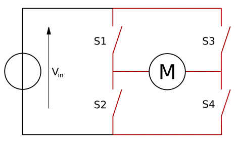
An H-bridge is built with four switches (mechanical or power semiconductor switches).
When the switches S1 and S4 are closed and S2 and S3 are open a positive voltage is applied across the motor.
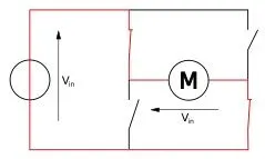
By opening S1 and S4 switches and closing S2 and S3 switches, this voltage is reversed, allowing reverse operation of the motor.
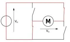
Moreover switching polarity of terminal voltage of motor, different operation can be done with H-Bridge by changing the switch opening and closing combination.
| Sl.no | S1 | S2 | S3 | S4 | RESULT |
| 1 | 1 | 0 | 0 | 1 | Motor terminal Voltage: positive |
| 2 | 0 | 1 | 1 | 0 | Motor terminal Voltage: negative |
| 3 | 1 | 0 | 0 | 0 | |
| 4 | 0 | 1 | 0 | 0 | |
| 5 | 0 | 0 | 1 | 0 | |
| 6 | 0 | 0 | 0 | 1 | |
| 7 | 1 | 0 | 1 | 0 | Braking |
| 8 | 0 | 1 | 0 | 1 | Braking |
| 9 | 1 | 1 | x | x | Short Circuit |
| 10 | x | x | 1 | 1 | Short Circuit |
In the above table, from condition 3-6, the motor coasts when the switch used is unidirectional and motor brakes when it uses bidirectional switches like IGBT or switch with diode connected in parallel to it (depends upon the back emf generated).
The last conditions 9 and 10 should be never do because it creates a short circuit and will damage the source, circuit, switches and other components.
SIMULINK MODEL:
Use command "power_Hbridge" to open the model "Speed control of a DC motor using H-Bridge".
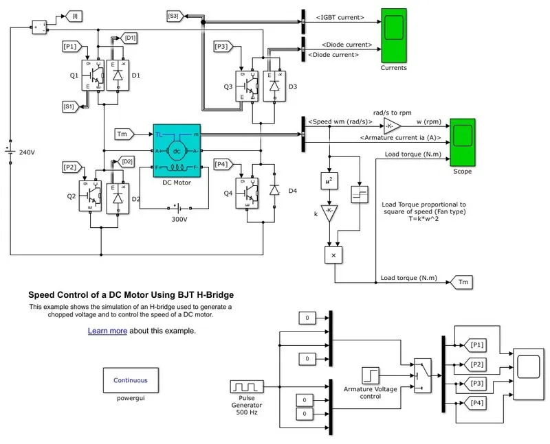
This is the simulink model
Input parameters given:
`V_(DC)` = 240 V
`V_(f)` = 300 V
Switch: IGBT with power diode in parallel
Motor rating: 5 HP, 240 V (rated terminal voltage), 1750 RPM, 300V (rated field voltage)
Switch `f_(sw)` = 500 Hz
Simulation time = 1 s
Motor reversal transition time: 0.5 s
The diodes are given in this H-bridge circuit is to maintain the armature current in continous conducting condition, otherwise the armature current doesn't conduct continously and motor will fail to run or even can cause damage.
OPERATION:
By changing the armature voltage control positive or negative, the terminal voltage can be changed by the control circuit in the model.
1. Positive terminal voltage:
In this condition, with duty cycle 75% given to switches,S1 and S4 and switches, S2 and S3 remains opened, the ouput terminal voltage is given by
`V_t = frac((240xx1.5xx10^(-3))+(-240xx0.5xx10^(-3)))(2xx10^(-3)) = 120 V`
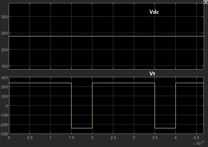
Thus the motor rotates in positiive direction.
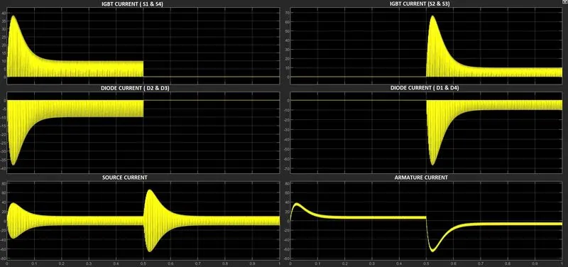
The positive voltage (Vdc) across motor terminal appears when the IGBT switches ( S1 and S4) are conducting and negative voltage (Vdc) appears when the diodes ( D2 and D3 ) are conducting.
2. Negative terminal voltage
In this condition, with duty cycle 75% given to switches,S2 and S3 and switches, S1 and S4 remains opened, the ouput terminal voltage is given by
`V_t = frac((240xx0.5xx10^(-3))+(-240xx1.5xx10^(-3)))(2xx10^(-3)) = -120 V`
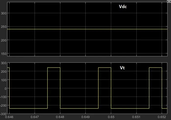
Thus the motor rotates in negative direction.
The positive voltage (Vdc) across motor terminal appears when the IGBT switches ( S2 and S3) are conducting and negative voltage (Vdc) appears when the diodes ( D1 and D4 ) are conducting.
SIMULATION RESULTS:
a) Current flow
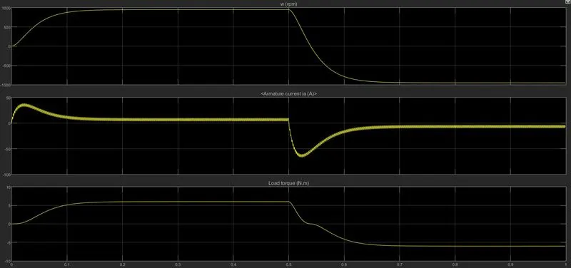
b) Motor parameter
1 B. Discussion of above results
Armature current:
a) 0 to 0.5s: Positive terminal voltage
At this condition the avg voltage across the motor terminal is +120V, during starting the motor rpm (`omega`) is 0. As back emf (Eb) is proportional to the `omega`, at starting Eb is 0.
From the armature current relation `I_a = frac(V_t - E_b)(r_a)` at starting the armature current will be high as Eb is zero. As motor gradually starts the `omega`also increase causing Eb to increase, at this condition the armature current rising rate falls and when the motor reaches to steady state speed, the armature current falls to rated current.
b) 0.5 to 1s: Negative terminal voltage
At this condition, the motor terminal average voltage is changed from +120 V to -120 V, as the motor is running in positive direction before 0.5s, the back emf build in the motor is -Eb w.r.to motor terminal. When the terminal voltage is changed to -120V at 0.5s, at this instance the motor rpm remains in positive direction due to rotational inertia of the rotor. Due to this the Eb is still negative.
From the armature current equation `I_a = frac(-V_t - E_b)(r_a)`, it can seen that now both Vt and Eb adds so that the armature current rate rises (negative) at faster rate than initial starting. This causes higher current shoot up than earlier shoot up during starting, the Eb remains negative until `omega`is positive, when `omega`becomes negative the Eb becomes positive wrto terminal, and the armature current rate of rising decreases and when the motor `omega`reaches steady state the the armature current becomes steady.
At steady state both armature current in positive and negative terminal voltage is same in magnitude.
CONCLUSION:
- Using Power diode along with switches make armature current to continously flow
- The source current fluctuates between positive and negative w.r.to the switching of switches in H-bridge
- The shootup of armature current depends upon the Back EMF, at starting the back EMF is low causes high Ia flow.
- The shootup of armature current just after reversal of voltage polarity of motor terminal is beacause at that instance the motor rpm (`omega`) is in positive direction due to rotational inertia, due to `omega`in positive direction Eb also remains in same polarity, this cause terminal voltage and Eb in same polarity causes higher current shootup than initial starting.
- To reduce the shootup, different starters are used like 3 point starters, 4 point starter, DC series motor starter.
1 C. Comparison od DC7 and H-Bridge
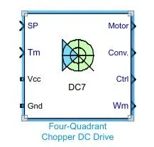
Four quadrant chopper DC drive (DC7) block:
This is the simulink block of four quadrant DC drive (DC7)
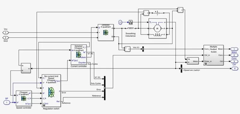
The circuit inside the block is
The simplified form of above circuit is shown below
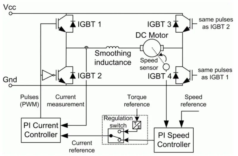
DC7 motor drive
- Four quadrant operation of DC motor can be used for variable speed application.
- DC motor speed control is easy and smooth.
- DC motor can be used for both motoring and generating purpose.
- Motor rotation can be changed CW and CCW by reversing the voltage polarity of the motor terminal, so motor can be run in both directions.
- Speed is varied by changing the voltage level.
- The four quadrant opeartions are:
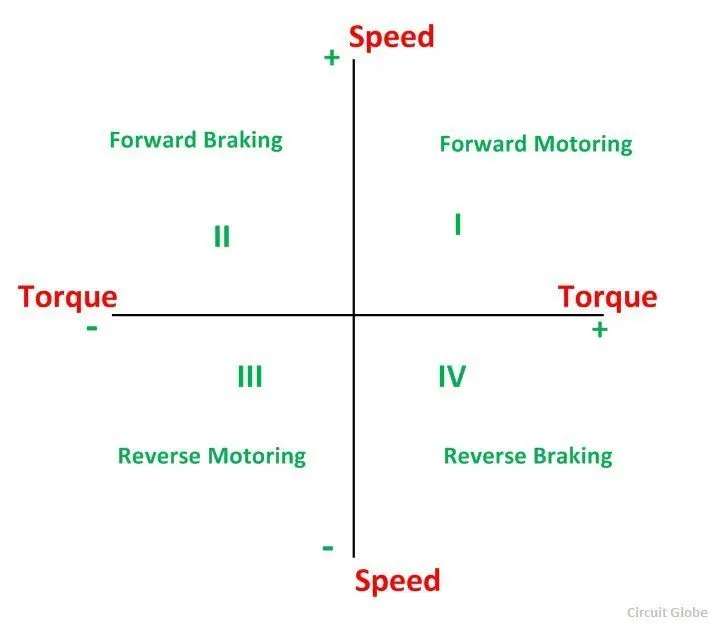
1st quadrant: Forward motoring
- Voltage polarity: +ve
- V > Eb
- Ia: +ve
- Power: +ve
- Torque: +ve (rotor torque < electromagnetic torque)
- Speed: +ve
- In this quadrant Electrical power is converted to mechanical power, i.e., motoring.
2nd quadrant: Forward braking/generating
- Voltage polarity: +ve
- Speed: +ve
- Torque: -ve (rotor torque > electromagnetic torque)
- Eb > V
- Ia: -ve
- Power: -ve
- In this quadrant Mechanical power is converted to Electrical power, it can be either used for braking, generating or both.
3rd quadrant: Reverse motoring
- Voltage polarity: -ve
- V > Eb (in magnitude)
- Ia: -ve
- Power: +ve
- Torque: -ve (rotor torque < electromagnetic torque(in magnitude))
- Speed: -ve
- In this quadrant Electrical power is converted to mechanical power, i.e., motoring, but speed of rotation is opposite.
4th quadrant: Reverse braking/generating
- Voltage polarity: -ve
- Speed: -ve
- Torque: +ve (rotor torque > electromagnetic torque(in magnitude))
- Eb > V (in magnitude)
- Ia: -ve
- Power: -ve
- In this quadrant Mechanical power is converted to Electrical power, it can be either used for braking, generating or both.
Comparison of DC7 drive vs H-Bridge drive
Structure of the circuit is similar but operation is different
| DC7 | H-Bridge |
| Suports four quadrant operation: Forward motoring, Forward braking, Reverse motoring and Reverse Braking | Supports only two mode of operation: Forward motoring and Reverse motoring |
| Regenerative braking is possible | Regenerative braking is not done |
| PWM modulated signals are complementory to each pair of switches (S1 & S4 and S3 & S2) | PWM siganls are given to any pair of switches and other pair is kept openend. |
| Efficiency is high compared to H-bridge |
2. TWO QUADRANT CHOPPER
The class C choper works in first two quadrant, i.e., 1st and 2nd quadrant (forward motoring and forward braking). The voltage polarity is not changed and the current direction is changed. So in first quadrant we get positive power and in 2nd quadrant we get negative power.
Operation of motor and its chara in both quadrant
1st quadrant: Forward motoring
- Voltage polarity: +ve
- V > Eb
- Ia: +ve
- Power: +ve
- Torque: +ve (rotor torque < electromagnetic torque)
- Speed: +ve
- In this quadrant Electrical power is converted to mechanical power, i.e., motoring.
2nd quadrant: Forward braking/generating
- Voltage polarity: +ve
- Speed: +ve
- Torque: -ve (rotor torque > electromagnetic torque)
- Eb > V
- Ia: -ve
- Power: -ve
- In this quadrant Mechanical power is converted to Electrical power, it can be either used for braking, generating or both.
A class C chopper (Two quadrant chopper) was developed in simulink based on the parameters obtained from
https://www.researchgate.net/figure/Separately-excited-DC-motor-parameters_tbl1_269809133
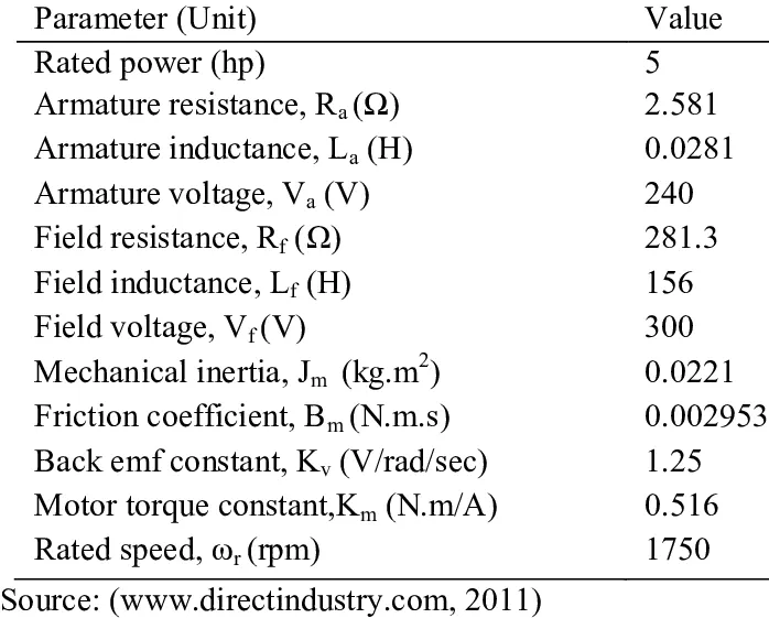
Simulink model: https://drive.google.com/file/d/1K5dsknmxdurjXVce66bNN-QirdeEyJYs/view?usp=sharing
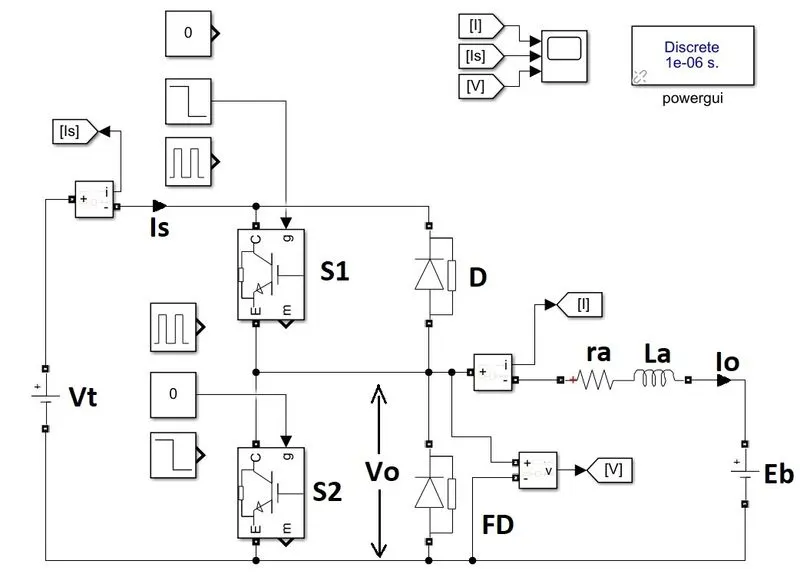
where,
Vt - Terminal Voltage
Is - Source current
Vo - Voltage across motor terminal
Io - Armature current / motor input current
Eb - Back emf
ra - armature resistance
La - armature inductance
S1 and S2 are Power SC switches
D - Diode
FD - Freewheeling Diode
1st Quadrant Operation:
Conditions given:
Vt = 240 V
Eb = 229 V ( = `K_v*omega_(rated)`)
Vt > Eb
a)Switch S1 closed Switch S2 opened
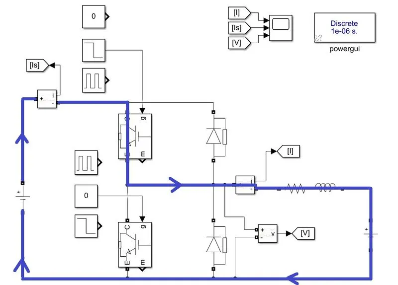
As shown in this figure the current flows in positive direction and thus the power is positive, in this condition the electrical power is converted into mechanical power, ie motoring.
Also the inductor (La) is charged during this time period and some power is loss in armature resistance.
- Vo = Vt = 240V
- Io = +ve
- Power = +ve
b)Switch S1 opened Switch S2 opened
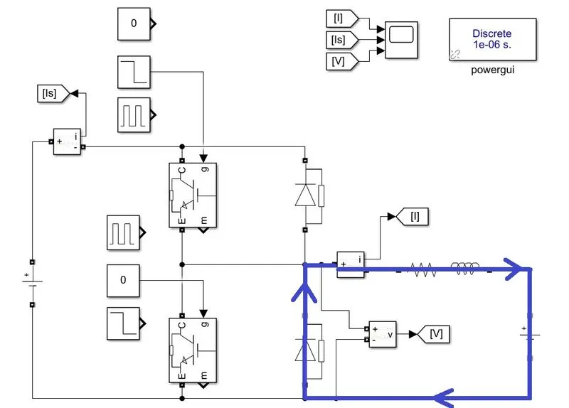
During S1: OFF and S2: OFF, at this condition the energy stored in the inductor is discharged through the FD, during discharging FD is in conduction mode so the Vo is 0 during this period, after conduction the Vo becomes equal to 'Eb'.
- Vo = 0 V (during freewheeling)
- Vo = Eb (after freewheeling)
- Io = +ve
- Power = +ve
The current waveform during 1st quadrant operation is (0 to 0.25s S1: ON & S2: OFF, at 0.25s S1: OFF & S2: OFF)
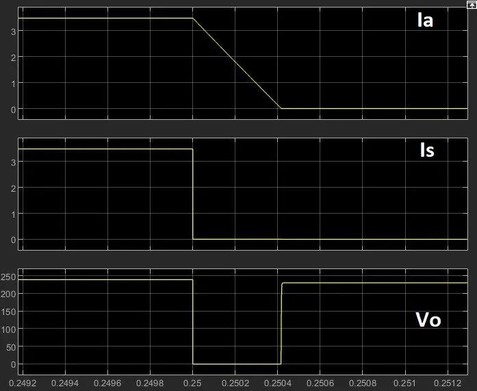
- When S1: ON (upto 2.5s), the source supplies a current of 3.5A and inductor is charged.
- When S1: OFF (at 2.5s), the source is cut off, now the armature current start to flow through FD or freewheeling through FD, during this period Vo = 0 V, inductor discharges.
- After freewheeling the inductor losses its energy and the Vo = Eb from this duration.
- During S1 switching ON and OFF, while keeping S2 OFF, the first qudrant operation is done, as Io and Vo remains positive. This is how 'Forward motoring' works.
2nd Quadrant operation:
Conditions:
Vt = 240 V
Eb = choosen greater than 240V = 250V (now `omega`> `omega_(no load)`)
Eb > Vt
a) S2: ON and S1: OFF
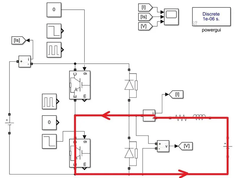
During this condition if Eb>Vt or E<=Vt this mode of operation works. In this mode braking is done by shorting the motor terminal. This causes a large current to flow in opposite direction due to Eb, this huge current creates a large opposing torque against the torque acting on the motor, due to this the motor braking is high.
- Vo = +ve
- Io = -ve
- Power = -ve
- In this condition the mechanical power is transferred to electrical energy, which converts to heat energy during braking.
b) S2: OFF and S1: OFF
This mode of regenerative braking works when Eb>Vt, during this mode the mechanical power converted to electrical power is fed to source and the source gets charged to save power.
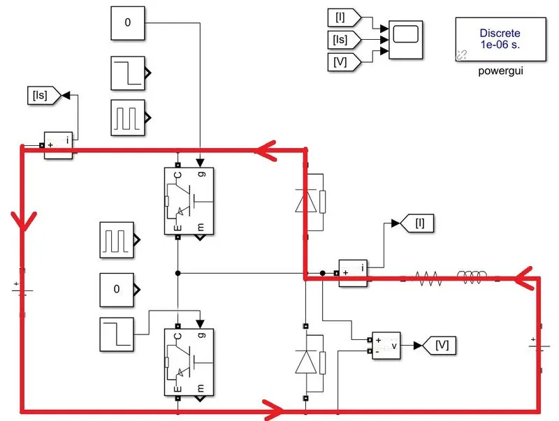
- Io = -ve
- Vo = +ve
- Power = -ve
- Regenerative braking mode.
- During this condition the source is get charged, due to this the potential difference between source and Eb is less, so that a low current is passed, as torque created is proportional to current a low torque is only created to oppose the load torque. So the braking will be less compared to above condition.
The current waveform during 2nd quadrant operation is (0 to 0.25s S2: ON & S1: OFF, at 0.25s S2: OFF & S1: OFF)
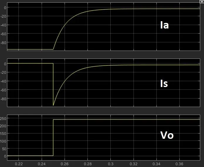
- When S2: ON (upto 2.5s), the current is short circuited through S2, Io nearly 100A, a huge current creates a large opposing torque and make braking faster.
- When S2: OFF (at 2.5s), now as Eb>Vt, the current is flow through Diode D to source, now the mechanical energy is converted into electrical energy, this energy is used by source to charge and hence energy is saved at same time a small braking torque is produced. And hence this mode is called regenerative braking.
- This mode continue till the motor stops.
- During S2 switching ON and OFF, while keeping S1 OFF, the second qudrant operation is done, as power remains negative. This how 'reverse braking' mode works.
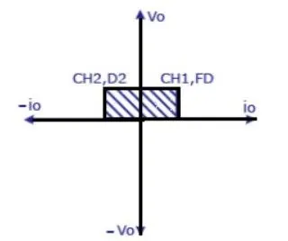
Thus two quadrant operation of DC drive has discussed with simulation results. The obtained area of operation is as shown below:
3. BLDC MOTOR
- BLDC motor is a Brush Less DC powered motor.
- The rotor consist of a Permanent magnet.
- The stator consist of coils, when energized produces magnetic field.
- The arrangement of rotor and stator coils is as shown in figure 3.1.
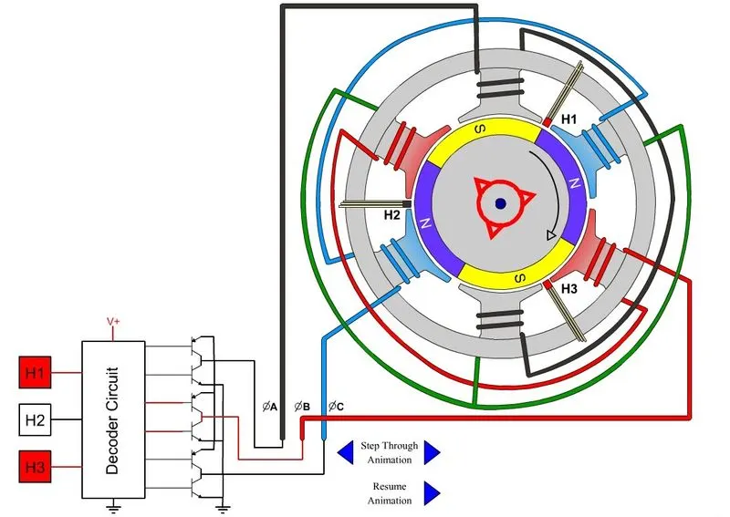
- In the above fig, the rotor consist of a pair of permanent magnets and stator with 6 poles.
- In common DC machine a commutator and brush system is used to change the current flow in the armature circuit. This DC machine produces sparks and brush drops and hence life of the machine is reduced. The stator coil arrangement is shown below
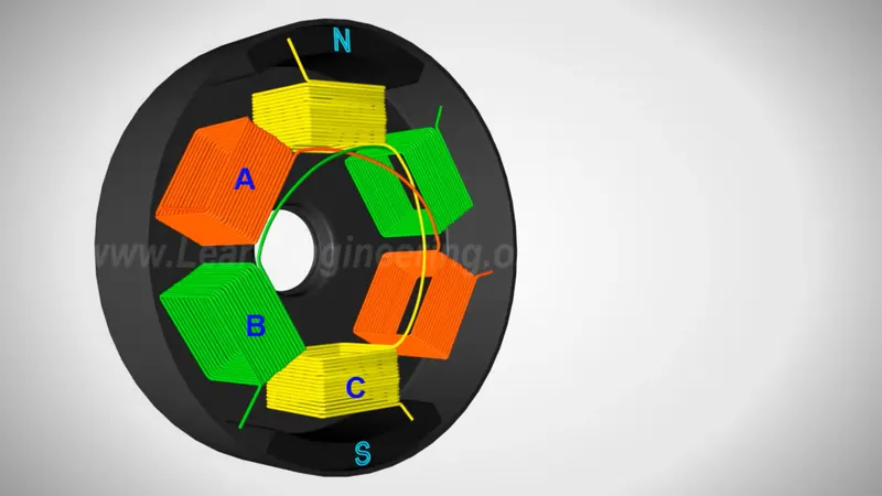
- In BLDC motor power converter is used to change the stator coil current and thus magnetic field produced is changed w.r.to the current.
Operation of BLDC motor:
- The operation of BLDC motor is similar to an AC synchronous machine, a rotating magnetic field (rmf) is created by the stator of synchronous machine and the rotor with permanent magnet follows the rmf to rotate the rotor. Similiarly BLDC motor also creates a rmf in stator and the rotor follows the rmf, and hence the rotor rotates.
- Based on no. of pole pair exited at a time, the operation of BLDC can be classified into two.
a) Attractive type
- When a pair of coil is energized it creates a North and South polarity, the rotor arranges its position such that rotors North polarity is moved to South polarity of stator and vice versa. Thus rotor starts to rotate and when the rotor reaches near to the central axis, the ecited pole of stator is unexcited and adjacent pole pairs are excited (same polarity that of adjacent pole), so that the rotor poles are attracted to the adjacent pole and starts to rotate. This cycle is repeated continously and thus rotor rotates.
- To give proper current to stator a propoer control signal is need to generated. This control signals are generated based on the position of rotor, the position of rotor is sensed by a hall effect position sensor (denoted by H in above fig.3.1).
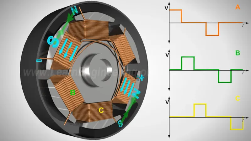
- Positive current through a pole pair makes the North pole in one side and South pole in opposite pole (ie, A pole is North and A' is South) and negative current through a pole pair makes the South pole in one side and North pole in opposite pole (ie, A pole is South and A' is North).
- Current input to the BLDC stator is shown in above image. By increasing the frequency and amplitude of the current input speed and torque of rotor can be increased respectively.
- The current phase is given by controller after sensing the position of the rotor position sensed by the hall effect sensor used in the BLDC.
b) Attractive and Repulsive type
- The working of Two pole pair excited at same time machine has more torque than single pole pair. In addition to the working of single pole pair one more pole pair is excited in this machine. The working of one pole pair which is used to attract the rotor pole is exactly same as that of single pole pair operation.
- The second pole pair is used to repel the rotor pole, the predecessor pole repels the rotor pole and successor pole attracts the rotor pole, position wrto the rotor poles.
- When the rotor pole leaves a stator pole, that stator pole becomes same polarity that of rotor pole, so there will be a repulsive force applied to the rotor.
- Thus two forces acts on the rotor repulsive and attractive force. Due to this the rotor experience torque more than that of attractive type only and also draws more power.
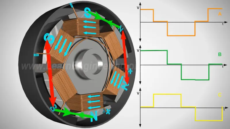
- The current input to the machine is given as shown in fig, these currents are given to the stator by power control circuit.
- The power controller takes inputs from position sensor to generate control signals according to position of rotor and also from user side.
- To increase speed and torque of machine, the power controller increases the frequency and amplitude of the current given to the stator respectively.
Advantages of BLDC over common DC machine
- No brushes, so spark and brush drop is no more in BLDC and hence more life and more efficient.
- High power to weight ratio.
- High speed
- Speed and torque can be adjusted instantaneulsy.
- High efficiency and low maintainence.
Reference of Images and working simulation of BLDC motor: https://www.youtube.com/watch?v=bCEiOnuODac